Abstract
To address the problem of cooperative work among right-angle coordinate robots in spacecraft structural plate mount tasks, an improved particle swarm optimization (PSO) algorithm was proposed to assign paths to three robots in a surface-mounted technology (SMT) machine. First, the optimization objective of path planning was established by analyzing the working process of the SMT machine. Then, the inertia weight update strategy was designed to overcome the early convergence of the traditional PSO algorithm, and the learning factor of each particle was calculated using fuzzy control to improve the global search capability. To deal with the concentration phenomenon of particles in the iterative process, the genetic algorithm (GA) was introduced when the particles were similar. The particles were divided into elite, high-quality, or low-quality particles according to their performance. New particles were generated through selection and crossover operations to maintain the particle diversity. The performance of the proposed algorithm was verified with the simulation results, which could shorten the planning path and quicken the convergence compared to the traditional PSO or GA. For large and complex maps, the proposed algorithm shortens the path by 7.49% and 11.49% compared to traditional PSO algorithms, and by 3.98% and 4.02% compared to GA.
1. Introduction
The space temperature difference varies greatly when working in space. In order to ensure the normal operation of internal equipment, it is necessary to mount an optical solar reflector (OSR) on the surface of the structural plate of the spacecraft to ensure the internal thermal equilibrium. Generally, the bonding between the OSR sheet and structural plates is achieved through an adhesive mixture sprayed on the structural plate, and currently, work carried out on spraying the adhesive and mounting the reflector is completed manually. With the development of space technology and the demand for spacecraft research, spacecraft structural plates are characterized by large size and complex structures. In the research project related to this paper, the maximum size of the spacecraft structural plate is 2.5 m × 3 m. The structural plate contains complex structures such as bosses and counter bores, and about 5000 OSR sheets (40 mm × 20 mm, 40 mm × 40 mm) need to be mounted on the surface. The manual mounting operation range is limited, and the intensity of the operation is high, which cannot guarantee the quality of the mount or the completion of effective mounting tasks within the specified curing time of the mixed adhesive (about 40 min).
To solve the above problems, it is necessary to design a reliable and effective automatic surface-mounted technology (SMT) machine to complete the relevant tasks. At present, SMT machines often adopt a multi-robot structure, which can be divided into arch type [1], turret type [2], and composite type [3] based on the motion mode of the mounting system and feeding system. In order to improve the overall efficiency of the mounting task, we have designed an SMT machine that uses multiple robots for synchronous mounting. To avoid the problems of missed and repeated mounting in the working process of multi-robot SMT machines, accelerate the global mounting speed, and improve overall efficiency, it is necessary to assign a suitable mounting path scheme for multiple robots based on the path planning algorithm.
Robot mount path planning belongs to the Multiple Traveling Salesman Problem (MTSP), which beginners use precise algorithms to solve [4]. With the expansion of the solution scale, scholars prefer to use heuristic algorithms, including ant colony optimization algorithms [5], GA [6], PSO [7], and simulated annealing algorithms [8]. Among them, the PSO algorithm requires fewer parameters and has a fast rate of convergence, which is widely used in solving path planning problems. However, traditional PSO algorithm experiences converge prematurely, resulting in many improved algorithms. These improvements typically use parameter adaptive control or integration with other algorithms to improve algorithm performance.
The adaptive control of parameters is one of the main methods to improve the search performance of the PSO algorithm. An improved PSO with adaptive weighted delay velocity (PSO-AWDV) is proposed by Xu [9], who updates the formula by changing the speed and updating the inertia weight based on the evolution state to make the particles jump out of the local optimal solution. Qiang [10] introduces a repulsive force between the particles, which affects particle velocity and improves searches for global optimal solutions. When judging premature convergence through convergence checking operations, when prematurity occurs, the repulsive force generated by the local optimum on all particles causes the population to jump out of the local optimum and continue searching. Tang [11] uses quadratic functions to calculate inertia weights and proposes a feedback learning PSO algorithm, which controls parameters by introducing an adaptive feedback mechanism. The second type of algorithm improvement is a hybrid algorithm that combines the PSO algorithm with other search algorithms to enhance performance. Das [12] proposes an innovative approach to compute an optimal collision-free trajectory path for each robot in a known and complex environment. The problem under consideration has been solved by employing an improved version of particle swarm optimization (IPSO) with evolutionary operators (EOPs). The performance of the algorithm confirms the avoidance of deadlock situations. The robustness of the algorithm is verified through the comparison with the state of the art. A trajectory planning method based on an improved hybrid particle swarm optimization algorithm is proposed by Duan [13] to address the issues of robot work efficiency and running stability. The results show that compared to traditional particle swarm optimization algorithms, this algorithm has a shorter running time and can effectively reduce the pulsation impact of the robotic arm, with better stability.
To overcome the disadvantages of low optimization accuracy and the prematurity of the canonical PSO algorithm, Tian [14] proposes an improved particle swarm optimization based on the interaction mechanism between leaders and individuals (PSO-IBLI), and uses it to implement robot global path planning. In the PSO-IBLI algorithm, in different stages, each particle learns from the elites according to different regulars. Moreover, the improved algorithm divides the execution state into two categories, where the parameters and the evaluation mechanisms are varied accordingly. In this way, the global best particles no longer walk randomly and have more learning objects. At the same time, other particles learn from not only the global best position, their historical best positions, but also the other elites. The learning strategy allows the search mode to remain in adaptive adjustment, and it improves the speed of convergence and promotes this algorithm to identify a more precise solution.
In order to obtain a path suitable for the safe work of the robot wall surface inspection robot in a GPS-denied environment, a global path-planning method for wall surface inspection robots is proposed by Tao [15] based on the improved GA. The influencing factor for GPS signal strength is introduced into the heuristic function in path planning for GA to address the aforementioned problem. Using the PSO algorithm, GA is initialized and the influencing term of GPS signal is introduced into the fitness degree function so as to achieve the point-to-point path planning of the vertical wall surface inspection robot.
To solve the problem of the robot often colliding with obstacles such as branches around the fruit during picking due to its inability to adapt to the fruit-growing environment, Gao [16] proposes an apple-picking robot path-planning algorithm based on the improved PSO. The main contents of the algorithm are as follows: first, the fruit and its surrounding branches are extracted from the 3D point cloud data, and the picking direction of the fruit is calculated; then, the point cloud on the surface of the fruit and branches is used to establish the spatial model of the obstacles; and finally, an improved PSO algorithm is proposed to plan the obstacle avoidance trajectory of the end-effector in space, which can dynamically adjust the velocity weights according to the trend of the particle fitness value and the position of the particle swarm center of mass. The experimental results show that the improved PSO has a faster convergence speed than the standard PSO.
Samar Hussni Anbarkhan [17] proposes an enhanced PSO algorithm in order to deal with the issue of the time and cost of the PSO algorithm being quite high when scheduling workflow tasks in a cloud computing environment. To reduce particle dimensions and ensure initial particle quality, intensive tasks are combined when scheduling workflow tasks. Next, the particle initialization is optimized to ensure better initial particle quality and reduced search space. Then, a suitable self-adaptive function is integrated to determine the best direction of the particles. The experiments show that the proposed enhanced PSO algorithm has better convergence speed and better performance in the execution of workflow tasks.
Aiming at the problems of low path success rate, easy precocious maturity, and easily falling into local extremums in the complex environment of mobile robot path planning, Liu [18] proposes a new particle swarm algorithm (RDS-PSO) based on a restart strategy and adaptive dynamic adjustment mechanism. When the population falls into local optimal or premature convergence, the restart strategy is activated to expand the search range by re-randomly initializing the group particles. An inverted S-type decreasing inertia weight and adaptive dynamic adjustment learning factor is proposed to balance the ability of the local search and global search. Finally, the new RDS-PSO algorithm is combined with cubic spline interpolation to apply to the path planning and smoothing processing of the mobile robots, the coding mode based on the path node as a particle individual is constructed, and the penalty function is selected as the fitness function to solve the shortest collision-free path.
Gul Faiza [19] introduces a recently developed Aquila Optimization Algorithm specifically configured for multi-robot space exploration. The proposed hybrid framework, “Coordinated Multi-Robot Exploration Aquila Optimizer” (CME-AO), is a unique combination of both deterministic Coordinated Multi-robot Exploration (CME) and a swarm-based methodology, known as an Aquila Optimizer (AO). A novel parallel communication protocol is also embedded to improve the multi-robot space exploration process while simultaneously minimizing both the computation complexity and time. This ensures the acquisition of an optimal collision-free path in a barrier-filled environment via generating a finite map.
Houssein Essam Halim [20] introduces IAO, a new swarm intelligence approach for addressing the challenge of task scheduling in cloud computing. The proposed method uses a conventional Aquila Optimizer (AO) and PSO as a hybrid method based on a novel transition mechanism. The proposed IAO method achieves better results and promising compared to other comparative methods; it is an excellent scheduling approach for solving any related scheduling problem.
Although scholars [9,10,11,12,13,14,15,16,17,18,19,20,21,22,23,24,25,26,27] have improved the PSO algorithm and achieved a high improvement effect, it is difficult to comprehensively consider the search ability, planned path length, robustness, and other aspects. Especially in the work related to multi-robot collaborative mounting tasks, the related coding, convergence performance, and other aspects still have room for improvement. Many PSO and GA hybrid algorithms have been published using PSO to solve for the initial path, and then GA to optimize the initial path. So, in the later iteration period, the population deteriorates due to the mutual learning between particles.
In order to solve the above problems, this paper studies the path planning of multi-robot cooperative mounting based on the PSO algorithm. Through the global optimization and local optimization of the adaptive inertia weight balancing algorithm, the fuzzy algorithm is used to dynamically assign learning factors to each particle in the calculation process, so as to speed up the rate of convergence of the algorithm. When the performance of particles is similar, a new population is generated by fusion GA to improve the diversity of the population. Experiments show that the algorithm proposed in this paper has stable performance, strong searching ability, fast convergence, and can be effectively applied to path planning work of SMT machines.
2. Mathematical Model
2.1. Analysis of Mount Process
The SMT machine used in the article consists of racks, material trays, mount robots, and the camera calibration system. The structure of the SMT machine is shown in Figure 1. The mount robot is driven by a linear motor, and each robot is equipped with two vacuum suction cups, which shuttle between the material tray and the structural plate to complete the mounting task.
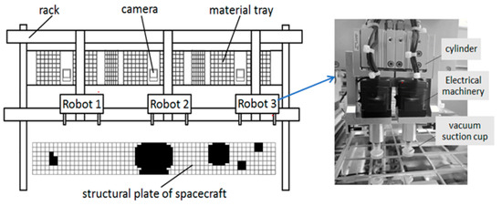
Figure 1.
Structure diagram of SMT machine.
The workflow of the SMT machine is as follows:
(1) The robot moves to the corresponding material tray based on the size of the OSR sheet to be attached, and two suction cups sequentially suck the OSR sheet.
(2) The robot moves above the camera to perform pose detection on the OSR sheet and calculate the offset between the center of the OSR sheet and the center of the suction cup.
(3) After the calibration is complete, the robot moves to the designated position for the mount.
(4) The robot returns to the material tray position to execute the next cycle.
From the workflow of the SMT machine, it can be seen that the reclaim and mount positions of different OSR sheets correspond to different motion paths. Due to the short movement distance of the robot in the z-axis direction, the mount sequence is the main factor affecting the efficiency.
2.2. Establishment of Optimization Objectives
Due to the correlation between mount efficiency and the total path of the robot, the objective of this algorithm optimization is to minimize the mount paths of three robots [28,29,30,31]. The objective function is as follows:
where f is the fitness function, and the smaller f, the smaller the total motion path of the robot under the sequence.
where represents the path length of the robot k, with k taking 1, 2, or 3. represents whether the mount is carried out at position i and j, taking 0 or 1. represents the picking distance of robot k. represents the distance from the position j where the robot k takes the OSR sheet to the camera o. represents the distance from camera o to position i. is the distance from position i to position j. is the distance from position j to the picking point of the material tray. The constraint condition is as follows:
Among them, Equation (3) indicates whether the current position is for the mount, Equation (4) indicates that the total number of OSR sheets is N, and Equations (5) and (6) indicate that each mount position is only assigned once.
3. Path Planning Based on Improved PSO Algorithm
3.1. Establishment of Environmental Maps
The spacecraft structural plate introduced in this article contains special structures such as bosses and counter bores, and the OSR sheets include two sizes: 40 mm × 40 mm and 40 mm × 20 mm. In order to accurately and completely represent the mounting area, the grid method is used to divide the spatial data into discrete units according to a fixed-size grid and form a grid map. The sizes of the OSR sheets installed in this study are only two, and in subsequent path-planning algorithms, the position of the OSR sheets needs to be added to the robot’s mounting sequence. When the cell size of the grid map is 40 mm × 40 mm, the complete grid and half grid can represent the different states of the two kinds of OSR sheets. Three representative typical structural plates were selected for the research, and the schematic diagram of the mounting structural plates is shown in Figure 2. It includes a small-sized structural plate (Map 1: 400 mm × 600 mm) and two large-sized structural plates (Map 2: 280 mm × 2320 mm, Map 3: 660 mm × 2120 mm). Map 3 has a wider width and higher structural complexity compared to Map 2, which makes the planning of the mounting tasks more difficult.
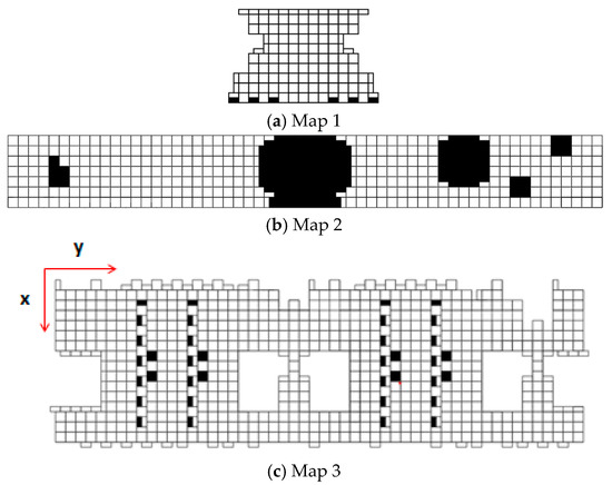
Figure 2.
Mount area map of structural plate.
Each grid in the grid map has a side length of 40 mm, and the status code in the grid represents the size and pose of the OSR sheet at that position. Status code 1 is used to indicate the mount of a 40 mm × 40 mm OSR sheet. Black indicates no mounting of an OSR sheet, or a convex and concave hole, denoted by 0. Then, 2, 3, 4, and 5 are used to represent four different poses for mounting 40 mm × 20 mm OSR sheets. According to the above rules, the corresponding digital matrix for the grid map is established, as shown in Figure 3.
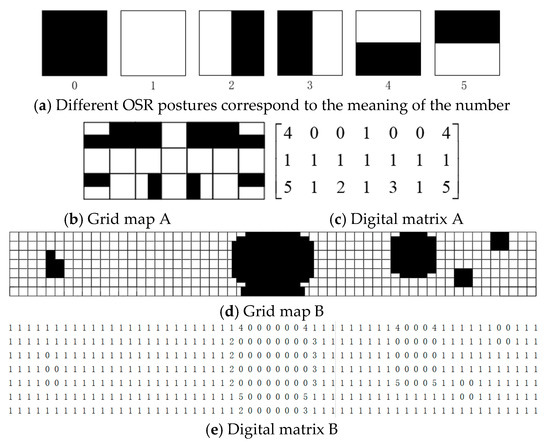
Figure 3.
Grid map and the corresponding digital matrix.
After converting the mount map into a grid map, each grid is numbered in order from left to right on each row to obtain the grid number set E = {1,2,3,...,N}. In order to facilitate access to the digital matrix and obtain information on whether the corresponding OSR under a certain number has been mounted and its mounting size, Equation (7) is used to decode the number into the coordinate form of (x, y). The coordinate axis is shown in Figure 2, and the symbol / represents the division result rounded down. The symbol % represents the remainder of the division result, which is equal to the remainder after dividing two numbers.
In the formula, n represents the real number of the current mount position, x and y represent the row and column number of the position on the grid map, and row represents the total number of columns in the grid.
The numbers in E are distributed evenly to the three robots as their initial mounting paths. The path information of three robots is saved as X in the matrix form of Equation (8), where X1, X2, and X3 respectively represent the mounting sequences of the three robots. The i-th row of the matrix represents the mounting sequence of the i-th robot, such as the mounting sequence of the first robot being 1, 17, 32…77, and 145. The route information shown in formula 8 is only an initial mounting sequence list, which is randomly assigned and becomes ordered as the iteration process progresses. Due to the fixed size of grid map cells, the actual distance between the real number and the origin of the map coordinates can be calculated. This method is intuitive and reasonable, making it convenient to calculate the total mounting path in the future.
3.2. Improved PSO Algorithm
The mount path plan in this article belongs to a discrete type problem, where the position of the particles represents the mount order of three robots, and the velocity of the particles represents the exchange sequence, changing the position of the particles [32]. The speed is composed of several arrays, each containing two mount position numbers to be exchanged. The update of the mount sequence is achieved by swapping the corresponding position numbers in the mount sequence. Particles learn from individual and group optimal particles with a certain probability to update their positions. Individual optimality refers to the optimal position of the particle during the optimization process, while group optimality refers to the position of the optimal individual in the entire population during the iteration process. In this article, a mathematical model of the discrete PSO algorithm is constructed using the method proposed by Zhou [25]. Equations (9) and (10) are used to update the velocity and position of the particle swarm, respectively [33].
In the formula, Vi+1 represents a set of exchange sequences, represents the mount sequence for the i-th iteration, pbest is the current optimal position of the particles, and gbest is the current optimal position of all particles; is the inertia weight; c1 and c2 are learning factors; Θ is an exchange sequence used to obtain the position of the current particle and convert it to the optimal position of the particle; is used to integrate the results of exchange sequences learned by particles; and uses to update the next position of the particles.
3.2.1. Inertia Weight Design
The inertia weight represents the degree to which the original speed is retained [34]. The smaller the value of , the slower the particle’s flight speed, and it manifests as a local fine search during the search process. At this point, the local optimization effect is good, while the global optimization effect is poor. The larger the value of , the better the global optimization effect. In order to balance global and local search, this article proposes an adaptive inertia weight, which is updated according to Equation (11).
In the formula, favg is the average fitness of the current population, and the fitness value that is better than favg is calculated by averaging it to favg1. Particles with fitness less than favg1 are divided into elite groups, where the particle has a smaller mount length and reduces inertia weight to search locally. Particles with fitness f between favg and favg1 are divided into high-quality groups, with appropriate mount length, maintaining the current inertia weight, and balancing their global and local search capabilities. Particles with fitness greater than favg are divided into low-quality groups, which have a longer mount path and increased inertia weight to search globally.
3.2.2. Dynamic Learning Factor Design
In Equation (9), c1 represents local cognitive ability, and c2 represents social cognitive ability. To avoid the premature convergence of the algorithm to local optima, c1 takes a larger value and c2 takes a smaller value, which enhances the attractiveness of individual optima to particles and improves their global search ability. In the later stage of the iteration, in order to accelerate convergence, c1 takes a smaller value and c2 takes a larger value, which increases the probability of particles learning from the optimal individual in the population and quickly approaches the global optimal solution. In traditional particle swarm optimization algorithms, c1 often uses a decreasing function, c2 uses an increasing function, and uses a linear decreasing function. However, during the iteration process, if some particles in the population have high fitness, but at this point is small and c2 is large, then these particles linger in the local optimal solution and the algorithm converges slowly. Through simulation, it is found that using the same fuzzy control update strategy as c2 for c1 does not significantly improve the algorithm performance and increases the computational complexity, making it difficult to ensure real-time requirements. For the individual learning factor c1 in this article, the adaptive update strategy of the traditional particle swarm optimization algorithm is still used, as shown in Formula (12).
In the formula, t represents the current number of iterations, and T represents the total number of iterations.
For the global learning factor c2, this paper proposes an update strategy based on particle performance and fuzzy control. By formulating fuzzy rules, each particle is assigned a learning factor according to the current performance of the particle and the inertia factor, so as to improve the rate of convergence of the algorithm.
The fitness value f is normalized using Equation (13) to ensure that the domain of the input and output variables is [0, 1].
To fuzzy the input and output, and f’ are divided evenly into seven intervals according to the range of [0.2, 0.9] and [0, 1]. Then, the fuzzy subset is described within these seven terms as NB (Negative Big), NM (Negative Middle), NS (Negative Small), O (Zero), PS (Positive Small), PM (Positive Middle), and PB (Positive Big). The membership function of a subset adopts a triangular membership function, and fuzzy rules are the key to fuzzy control [35]. The design criterion of fuzzy rules in this article is that the smaller the fitness value, the larger the global learning factor c2; the larger the inertia weight , the smaller the c2. The output surfaces of learning factors c1 and c2 is shown in Figure 4. The specific fuzzy rules are shown in Table 1. The input variables are reasoned and decided according to Table 1, and the barycenter method is used to defuzzify and output the change of global learning factor c2. The basic idea of the barycenter method is to determine the position of the barycenter of a fuzzy set by calculating the sum of the product of the membership degree of the variable and the value of the variable, thus representing the degree of fuzziness of the fuzzy set. In the barycenter method, the membership of each variable indicates the importance of the variable in the fuzzy set, and the value of the variable indicates the position of the variable in the fuzzy set. Through the formula of the barycenter method, the fuzzy set can be mathematically processed to realize fuzzy control and fuzzy decision making from the system.
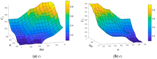
Figure 4.
Output surfaces of learning factors c1 and c2.

Table 1.
Fuzzy rules.
3.2.3. Processing of Local Optimal Solutions
During the iteration process, variance is used to evaluate the similarity of the particles [36]. If the variance is small, it indicates that the fitness of particles is relatively close, and the similarity of the particle mount path in the population is high. If we continue to use this population for searching, the algorithm may fall into a local optimal solution. By selecting a GA, crossover operator, and elite group, a new population is formed to increase population diversity. If the method of random crossover is adopted, more low-quality particles will be generated, which will reduce the rate of convergence of the algorithm. Therefore, this paper uses the fusing GA to sort the particles according to the fitness value, divide the particles with the highest fitness into elite groups, and not participate in subsequent cross operations. Assuming there are m other particles, the first m/2 particles form the high-quality group, and the second m/2 particles form the low-quality group. From each of these particles, one particle is selected for single-point crossing to generate two new individuals. The improved PSO algorithm process is shown in Figure 5 and the improved PSO framework is shown in Algorithm 1.
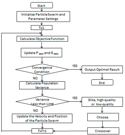
Figure 5.
Flowchart of the improved PSO algorithm.
| Algorithm 1: Improved PSO framework |
| 1: Set the population size, maximum iteration times iternum, maximum and minimum of inertia weights 2: Initialize particle position and velocity 3: Calculate the fitness value fit of the initial population, update the optimal particle mounting order Gbest (1) and the minimum fitness value of the population Gbest_ fit (1) 4: while iter < iternum 5: sort the elite, high-quality and low-quality groups 6: Calculate , c1, c2 7: for i = 1 to size 8: Calculate the new particle velocity v(i) 9: Calculate the new position pop() 10: Calculate the new fit and the variance fit_var 11: if fit_var < 1000 12: Generate a new population 13: Calculate fit of the new population 14: for i = 1 to size 15: if fit(i) < Pbest_fit(i) Pbest_fit (i) = fit(i); Pbest (i) = pop(i); end 16: [maxvalue,max_index] = min(fit) 17: if max value < Gbest_fit(iter-1) Gbest_fit(iter) = max value; Gbest(iter) = pop(max_index); else Gbest_fit(iter) = Gbest_fit(iter-1); Gbest(iter) = Gbest(iter-1) 18: iter = iter + 1 19: Output minimum Gbest_fit and the corresponding index 20: Output Gbest(index) |
4. Simulation Experiment Analysis
4.1. Algorithm Parameter Settings
The population size affects the computational time and search ability of algorithms, and different population sizes are selected based on the size of the problem and optimization objectives [37]. The population size is small, and the calculation time is short. However, during the iteration process, there are fewer learning samples and more attention is paid to one’s own learning, making it difficult to generate a global optimal solution. The population size is large, and the differences between particles are large, making it easy to obtain the global optimal solution. However, the computational complexity is large, and the solution takes a long time. For simple problems, the total number of particles is usually selected as 20–40. When there is a high demand for solution quality, the value is 40–100; when facing large and complex optimization problems, the values are 100–200.
From Figure 6a, it can be seen that as the population size increases, the percentage of optimized paths relative to the average mount decreases rapidly, indicating that the algorithm’s search performance can be improved by increasing the population size. However, when the population size reaches 100, increasing the number of individuals in the population does not significantly improve the algorithm’s search ability, so the population size is determined to be 100.
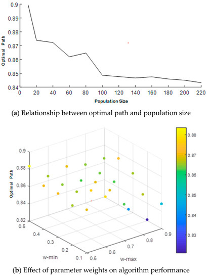
Figure 6.
Effect of inertia weights on algorithm performance.
The inertia weight ω affects the search performance of the algorithm. Figure 6b shows the impact of inertia weight size on algorithm performance, where , and . From Figure 6b, it can be seen that when , , the solved mount path is the shortest and the algorithm has the best search performance.
To analyze the results of the improved algorithm proposed in this article, the GA and PSO algorithm are run 10 times. The number of particles is set to 100, the number of iterations to 2000, the crossover probability of the GA to 0.8, and the mutation probability to 0.05.
4.2. Convergence Performance Analysis
The mount task of large-sized structural boards requires multiple processes according to the divided mount area. The SMT machine proposed in this article can mount seven rows of OSR sheets in one large process. Therefore, the structural board shown in Figure 2 is selected to establish a grid map, and the convergence curves of the mount paths optimized by each algorithm are shown in Figure 7.
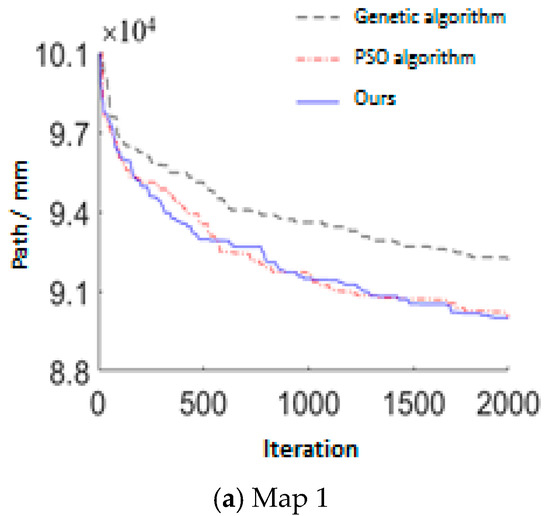
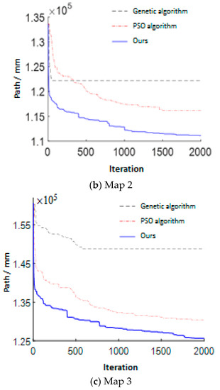
Figure 7.
Comparison chart of convergence performance.
From Figure 7, it can be seen that the PSO algorithm converges quickly in the early stage of iteration. Due to its poor global search ability, it has fallen into a local optimal solution at 78 iterations, making it difficult to ensure the quality of the solution. Although GA can avoid prematurity, its early rate of convergence is low. The improved PSO algorithm in this paper makes full use of the fast search speed of the PSO algorithm to iterate in the early stage, finds a shorter mount path in a short time, and improves the search performance and calculation speed of the algorithm through fusing GA and its global search characteristics.
The mount sequence of the three robots for the structural plate in Figure 2b and Figure 3d is shown in Figure 8. The depth of the colors and the number in the cells in the figure specifically represent the mount sequence of the robots. The overall working trend of the three robots is to move from left to right, and there are no instances of remount or missed mount.
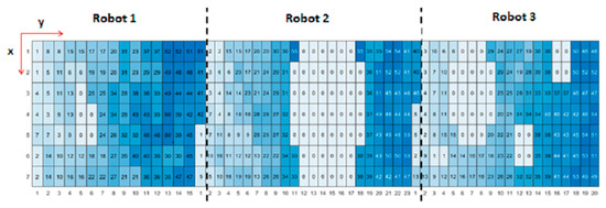
Figure 8.
Mount sequence planning diagram of the three robots.
The motion speed of the robot is 2 m/s, and the acceleration is 12 m/s2. The actual positions of the three robots can be calculated according to the speed displacement formula. In Figure 9, the x-axis is the time, and the y-axis represents the coordinates of the robot in the y direction, as shown in Figure 8. The position tracks of the robots do not cross, indicating that the robots did not collide during the whole mount process.
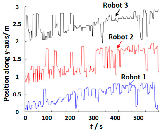
Figure 9.
Position map of 3 robots on the y-axis at working time.
4.3. Convergence Performance Analysis
To demonstrate the stability of the improved PSO algorithm in this article, the traditional PSO algorithm and GA were used as comparative algorithms to solve three different specifications of structural board mount maps in Figure 2 20 times. The path solution results are shown in Table 2, and the algorithm stability is shown in Figure 10.
Table 2.
Comparison of algorithm effects.
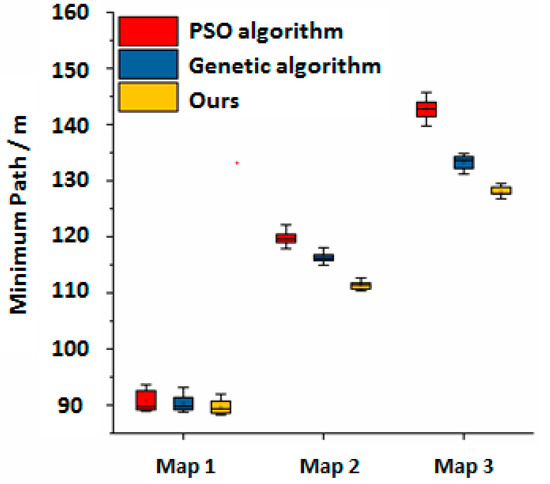
Figure 10.
Comparison of algorithm effects in three maps.
From Table 2, it can be seen that due to the small size of Map 1, the three algorithms perform similarly, and the planned mount paths are relatively close, resulting in a small performance gap. However, for large and complex maps such as Map 2 and Map 3, the improved PSO algorithm plans for a shorter average path. In Map 2, the proposed algorithm shortens the path by 7.49% compared to traditional PSO algorithms and 3.98% compared to GA. In Map 3, the proposed algorithm shortens the path by 11.49% compared to traditional PSO algorithms and 4.02% compared to GA. From Figure 10, it can be seen that for the three sizes of map solutions, the improved PSO algorithm in this paper has more concentrated results, smaller differences between the maximum and minimum paths, and more stable algorithm performance. The mount task effect of the spacecraft OSR sheets is shown in Figure 11.
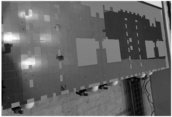
Figure 11.
Mount task effect of spacecraft OSR sheets.
5. Conclusions
In this paper, relevant research is carried out to realize the most effective path planning for the collaborative mounting of three robots in a spacecraft OSR structural plate SMT machine. By improving the calculation method of inertia weight in PSO, updating the learning factor by fuzzy control, and integrating with GA, the problems of PSO being prone to becoming stuck in local solutions and the poor quality of the path optimization results have been solved. The experimental results show that the proposed algorithm has shorter planning paths, smaller differences between the maximum and minimum paths, stable performance, strong search ability, fast convergence, and can be effectively used for the path planning of SMT machines. In the future, we will further improve and optimize the algorithm, conduct research on mounting path planning for larger and more complex structural plates and more mounting robot actuators, and provide more technical support for the research of OSR automatic SMT machines for spacecraft structural plates. The performance of the proposed algorithm was verified with the simulation results, which could shorten the path planning and quicken the convergence compared to the traditional PSO or GA.
Author Contributions
Methodology, X.L. (Xudong Li); Software, X.L. (Xudong Li), B.T. and S.H.; Formal analysis, S.H.; Writing—original draft, X.L. (Xudong Li) and B.T.; Writing—review & editing, X.L. (Xudong Li), X.L. (Xinxin Li), Y.L., C.L. and J.L.; Project administration, J.L. All authors have read and agreed to the published version of the manuscript.
Funding
This research received no external funding.
Data Availability Statement
Not applicable.
Conflicts of Interest
The authors declare no conflict of interest.
References
- Peng, Q.; Cao, L.; Wan, T.; Wang, L.; Xu, S.; Li, X. Optimization of mounting path for arch style mounting machine. J. Chongqing Univ. 2022, 45, 51–60. [Google Scholar]
- Yin, L.; Gao, L.; Li, D.; Hu, M. Component mount optimization for turret mounting machine based on improved cellular genetic algorithm. J. Huazhong Univ. Sci. Technol. 2015, 43, 113–117+132. [Google Scholar]
- Lu, T.; Yu, Z.; Zheng, X. Dual-gantry mounting machine scheduling based on cellular bat algorithm. Mod. Manuf. Eng. 2017, 444, 22–28+101. [Google Scholar]
- Zhang, S.; Guo, G. Review of multiple traveling salesman model and its application. J. Front. Comput. Sci. Technol. 2022, 16, 1516–1528. [Google Scholar]
- Qin, X.; Zong, Q.; Li, X.Y.; Zhang, B.Y.; Zhang, X.Y. Task allocation of multi-robot based on improved ant colony algorithm. Aerosp. Control Appl. 2018, 44, 55–59. [Google Scholar]
- Wang, Y. The hybrid genetic algorithm with two local optimization strategies for traveling salesman problem. Comput. Ind. Eng. 2014, 70, 124–133. [Google Scholar] [CrossRef]
- Qiao, S.; Lv, Z.; Zhang, N. Improved particle swarm optimization algorithm based on hamming distance for traveling salesman problem. J. Comput. Appl. 2014, 70, 124–133. [Google Scholar]
- Lin, Y.; Bian, Z.Y.; Liu, X. Developing a dynamic neighborhood structure for an adaptive hybrid simulated annealing-tabu search algorithm to solve the symmetrical traveling salesman problem. Appl. Soft Comput. 2016, 49, 937–952. [Google Scholar] [CrossRef]
- Xu, L.; Song, B.Y.; Cao, M.Y. An improved particle swarm optimization algorithm with adaptive weighted delay velocity. Syst. Sci. Control Eng. 2021, 9, 188–197. [Google Scholar] [CrossRef]
- Qiang, N.; Kang, F. Application of a new acceleration particle swarm optimization for solving multiple traveling salesman problems. J. Shaanxi Norm. Univ. (Nat. Sci. Ed.) 2015, 43, 36–42. [Google Scholar]
- Tang, Y.; Wang, Z.D.; Fang, J.A. Feedback learning particle swarm optimization. Appl. Soft Comput. 2011, 11, 4713–4725. [Google Scholar] [CrossRef]
- Das, P.K.; Jena, P.K. Multi-robot path planning using improved particle swarm optimization algorithm through novel evolutionary operators. Appl. Soft Comput. 2020, 92, 106312–106336. [Google Scholar] [CrossRef]
- Duan, Q.; Xin, S. Robot trajectory planning based on improved hybrid particle swarm optimization. Mach. Tool Hydraul. 2022, 50, 50–56. [Google Scholar]
- Tian, S.; Li, Y.; Li, J.; Liu, G. Robot global path planning using PSO algorithm based on the interaction mechanism between leaders and individuals. J. Intell. Fuzzy Syst. 2020, 39, 4925–4933. [Google Scholar] [CrossRef]
- Tao, Y.; Wen, Y.; Gao, H.; Wang, T.; Wan, J.; Lan, J. A Path-Planning Method for Wall Surface Inspection Robot Based on Improved Genetic Algorithm. Electronics 2022, 11, 1192. [Google Scholar] [CrossRef]
- Gao, R.; Zhou, Q.; Cao, S.; Jiang, Q. Apple-Picking Robot Picking Path Planning Algorithm Based on Improved PSO. Electronics 2023, 12, 1832. [Google Scholar] [CrossRef]
- Anbarkhan, S.H.; Rakrouki, M.A. An Enhanced PSO Algorithm for Scheduling Workflow Tasks in Cloud Computing. Electronics 2023, 12, 2580. [Google Scholar] [CrossRef]
- Liu, L.; Xu, H.; Wang, B.; Zhang, R.; Chen, J. A Study on Particle Swarm Algorithm Based on Restart Strategy and Adaptive Dynamic Mechanism. Electronics 2022, 11, 2339. [Google Scholar] [CrossRef]
- Gul, F.; Mir, A.; Mir, I.; Mir, S.; Islaam, T.U.; Abualigah, L.; Forestiero, A. A Centralized Strategy for Multi-Agent Exploration. IEEE Access 2022, 10, 126871–126884. [Google Scholar] [CrossRef]
- Halim, H.E.; Mohamed, A.E.; Diego, O.; Laith, A. Aquila Optimizer Based PSO Swarm Intelligence for IoT Task Scheduling Application in Cloud Computing. Integr. Meta-Heuristics Mach. Learn. Real-World Optim. Probl. 2022, 1038, 481–497. [Google Scholar]
- Zeng, N.; Wang, Z.; Liu, W.; Zhang, H.; Hone, K.; Liu, X. A Dynamic Neighborhood-Based Switching Particle Swarm Optimization Algorithm. IEEE Trans. Cybern. 2022, 52, 9290–9301. [Google Scholar] [CrossRef] [PubMed]
- Kumar, P.H.; Kumar, D.P.; Sucheta, P. Optimal path planning of multi-robot in dynamic environment using hybridization of meta-heuristic algorithm. Int. J. Intell. Robot. Appl. 2022, 6, 625–667. [Google Scholar]
- Lin, S.; Liu, A.; Wang, J.; Kong, X. An intelligence-based hybrid PSO-SA for mobile robot path planning in warehouse. J. Comput. Sci. 2023, 67, 101938. [Google Scholar] [CrossRef]
- Liu, Y.; Jiang, D.; Yun, J.; Sun, Y.; Li, C.; Jiang, G.; Kong, J.; Tao, B.; Fang, Z. Self-Tuning Control of Manipulator Positioning Based on Fuzzy PID and PSO Algorithm. Front. Bioeng. Biotechnol. 2022, 9, 817723. [Google Scholar] [CrossRef]
- Zhou, H.L.; Song, M.L.; Pedrycz, W. A comparative study of improved GA and PSO in solving multiple traveling salesmen problem. Appl. Soft Comput. 2018, 64, 564–580. [Google Scholar] [CrossRef]
- Sun, K.; Riedel, C.A.; Urbani, A.; Simeoni, M.; Mengali, S.; Zalkovskij, M.; Bilenberg, B.; de Groot, C.; Muskens, O.L. VO2 thermochromic metamaterial-based smart optical solar reflector. ACS Photonics 2018, 5, 2280–2286. [Google Scholar] [CrossRef]
- Heydari, V.; Bahreini, Z. Synthesis of silica-supported ZnO pigments for thermal control coatings and analysis of their reflection model. J. Coat. Technol. Res. 2018, 15, 223–230. [Google Scholar] [CrossRef]
- He, J.; Cen, Y.; Li, Y.; Alelaumi, S.M.; Won, D. A novel mounting method for mini-scale passive components in surface mount technology. Int. J. Adv. Manuf. Technol. 2021, 115, 1475–1485. [Google Scholar] [CrossRef]
- Castellani, M.; Otri, S.; Pham, D.T. Printed circuit board assembly time minimisation using a novel bees algorithm. Comput. Ind. Eng. 2019, 133, 186–194. [Google Scholar] [CrossRef]
- Hsu, H.P. Printed circuit board assembly planning for multi-head gantry SMT machine using multi-swarm and discrete firefly algorithm. IEEE Access 2020, 9, 1642–1654. [Google Scholar] [CrossRef]
- Gan, R.; Guo, Q.; Chang, H.; Yi, Y. Improved ant colony optimization algorithm for the traveling salesman problems. J. Syst. Eng. Electron. 2010, 21, 329–333. [Google Scholar] [CrossRef]
- Wang, Z.; Li, Y.; Shuai, K.; Zhu, W.; Chen, B.; Chen, K. Multi-objective trajectory planning method based on the improved elitist non-dominated sorting genetic algorithm. Chin. J. Mech. Eng. 2022, 35, 7. [Google Scholar] [CrossRef]
- Shim, J.H.; Nam, T.H. Machine vision based automatic measurement algorithm of concentricity for large size mechanical parts. J. Phys. Conf. Ser. 2017, 806, 012002. [Google Scholar] [CrossRef]
- Kumar, R.; Luo, Z. Optimizing the operation sequence of a chip placement machine using TSP model. IEEE Trans. Electron. Packag. Manuf. 2003, 26, 14–21. [Google Scholar] [CrossRef]
- Torabi, S.A.; Hamedi, M.; Ashayeri, J. A new optimization approach for nozzle selection and component allocation in multi-head beam-type SMD placement machines. J. Manuf. Syst. 2013, 32, 700–714. [Google Scholar] [CrossRef]
- Seth, A.; Klabjan, D.; Ferreira, P.M. A new novel local search integer-programming-based heuristic for PCB assembly on collect-and-place machines. Math. Program. Comput. 2016, 8, 1–45. [Google Scholar] [CrossRef]
- Wang, W.C.; Chen, S.L.; Chen, L.B.; Chang, W.J. A machine vision based automatic optical inspection system for measuring drilling quality of printed circuit boards. IEEE Access 2017, 5, 10817–10833. [Google Scholar] [CrossRef]


Disclaimer/Publisher’s Note: The statements, opinions and data contained in all publications are solely those of the individual author(s) and contributor(s) and not of MDPI and/or the editor(s). MDPI and/or the editor(s) disclaim responsibility for any injury to people or property resulting from any ideas, methods, instructions or products referred to in the content. |
© 2023 by the authors. Licensee MDPI, Basel, Switzerland. This article is an open access article distributed under the terms and conditions of the Creative Commons Attribution (CC BY) license (https://creativecommons.org/licenses/by/4.0/).