Article

Proof of Concept of the Use of the Parametric Effect in Two Media with Application to Underwater Acoustic Communications

by
María Campo-Valera
1,*,
Ignacio Rodríguez-Rodríguez
2,
José-Víctor Rodríguez
1 and
Luis-Jorge Herrera-Fernández
3
1
Departamento de Tecnologías de la Información y las Comunicaciones, Universidad Politécnica de Cartagena, Antigones, Plaza del Hospital 1, 30202 Cartagena, Spain
2
Departamento de Ingeniería de Comunicaciones, Universidad de Málaga, 29010 Málaga, Spain
3
Engineering Faculty–Sound Engineering, Universidad de San Buenaventura, Bogotá Campus, Bogotá 110111, Colombia
*
Author to whom correspondence should be addressed.
Electronics 2023, 12(16), 3459; https://doi.org/10.3390/electronics12163459
Submission received: 9 July 2023 / Revised: 28 July 2023 / Accepted: 12 August 2023 / Published: 15 August 2023
(This article belongs to the Special Issue Advances in Signal Processing for Wireless Communications)

Abstract

:
Nonlinear acoustics offers a new range of acoustic applications that are currently being exploited. The parametric nonlinear effect—the occurrence of low frequencies with modulated high-frequency emission—is of particular interest. This work provides a systematic exposition of the theoretical framework on which the so-called parametric nonlinear effect is based. In relation to this behavior is an analytical discussion of how to solve the problem for two cases: (i) nonlinear behavior with modulation, and (ii) parametric emission of two monochromatic waves (bi-frequency). Subsequently, parametric emission experiments were carried out in air and water using the same transducer to compare the results with those obtained theoretically. In this sense, directivity and attenuation measurements are obtained. Conclusively, this research offers a proof of concept for underwater acoustic communications. It is characterized by the transmission of a binary sequence through Frequency Shift Keying (FSK) modulation, and the subsequent decoding of each received bit (either 1 or 0) utilizing advanced signal processing with the cross-correlation technique. This paper accentuates the significant potential of employing the parametric effect for specialized communication applications.

1. Introduction

Parametric acoustic sources use piezoelectric transducers and modulated ultrasonic signals to produce highly directed sound in the audible and ultrasonic ranges over a wide frequency spectrum. This device is based on parametric generation and is named for the low-noise parametric amplifier used as a replacement for helium-cooled 4 G Hz masers in satellite signals in the 1970s. These amplifiers take advantage of nonlinearities exhibited by a varactor diode fed by a signal to be amplified and by a square pump signal to obtain a new signal that has a frequency (called “idler”) equal to the sum, or difference of, the signals that fed the varactor diode. This circuit creates a theoretical negative resistance in the diode, which translates into a practical amplification of the signal [1].
These devices achieve very narrow directivity by minimizing sidelobe energy. Therefore, many applications use parametric generation to obtain this characteristic, such as individualized music listening and in places where there are no physical barriers to delimit the sound.
The first studies on the nonlinear interaction of underwater acoustic waves in the ultrasound range (primary) to produce new waves (secondary) in the audible range was performed by Westervelt in 1957 [2], called “scattering of sound by sound”. He created a nonlinear transduction technique capable of generating collimated sound beams without sidelobes. Starting from the equations of fluid dynamics, he obtained the acoustic pressure distribution of the (secondary) waves produced by the nonlinear interaction of the two collimated (primary) plane waves; that is, from two tones of given frequencies f 1 and f 2 , a secondary low-frequency wave equal to the difference frequency of the primary waves f d = | f 1 + f 2 | with similar directivity was produced. From this, he deduced the far-field attenuation and directivity from the difference frequency, called “a parametric”. This technique was applied to low-frequency sonar (sound navigation and ranging) used to locate underwater objects.
After Westervelt’s study was published in 1963 [3], Berktay followed in 1965 [4] and 1974 [5], with publication of a more precise development of Westerlvelt’s studies for a spherical or cylindrical propagation of primary waves underwater. In addition, he extended the analysis of two pure tones to the case of the “emission of a primary wave modulated in amplitude at low frequency (envelope)”, which caused the medium itself to demodulate the original signal in the low frequency (parametric), a process known as the “self-demodulation” of the medium.
In 1975, Benneth and Blackstock [6] created an application of the parametric effect in air using a circular transducer. They observed that when emitting with two frequencies, 18.6 and 23.6 kHz, the difference frequency of 5 kHz had a narrow beamwidth similar to that of the primary frequencies with few secondary lobes. Finally, in 1983, Yoneyama [7] proposed the idea of a parametric loudspeaker using 547 transducers and amplitude modulation (AM).
In 2002, Pompei [8] (Sections 4 and 5), founder of the company Holosonics, established himself as a pioneer in the creation of parametric loudspeakers. These have higher directivity compared to conventional electrodynamic loudspeakers and very low distortion levels, making them suitable for high-quality audio reproduction. Pompei demonstrated a parametric loudspeaker using a large series of experimental measurements and consolidating the theoretical principles, which have subsequently been used by many companies for commercial manufacturing.
In general, parametric acoustic sources have been the subject of considerable research over the last 70 years [7,9,10,11,12,13,14], with the first application being related to sonar systems [15,16,17] using water as the transmission medium.
Currently, several parametric communication systems have been proposed for digital data transmission [18,19,20,21]. These include the MAST project PARACOM [22], which modulates parametric acoustic signals to achieve long-range communication.
For information transmission applications in water, acoustic communication systems are being developed because sound waves are better adapted to the marine environment. However, their propagation in an underwater acoustic channel has important limitations due to the limited bandwidth, multipath, and refraction properties of the medium, among others. For this reason, parametric communication systems are of particular interest since the propagation of underwater acoustic waves is essentially a nonlinear process. Thus, using the modulation theory proposed by Berktay in 1974 [5], the frequency difference f d will propagate over long distances on the order of kilometers because its low-frequency spectral component has the advantage of obtaining highly directional beams, thus reducing multipath propagation.

Approaches

This work provides a deeper understanding of the dynamics of nonlinear acoustic waves and their behavior in different air and water media, thereby providing insight into the physics of sound propagation. It also highlights the possibility of exploiting the parametric effect for communication applications. In this sense, by adequately selecting the encoding, opportunities open up to develop underwater acoustic communication systems with directivity and range that are considerably superior to those of traditional systems.
The paper is organized as follows: Section 2 presents the phenomenology associated with nonlinear propagation. Section 3 presents the analytical development by formulating the nonlinear Westervelt equation and two solutions to the problem: exciting the medium with two primary waves and using modulation. Section 4 presents the experimental setup and developments in air and water for three difference frequencies f d of 10, 15 and 30 kHz, performing directivity and attenuation measurements in air and water. In Section 5, the results of the previous measurements are presented, discussed, and contrasted with theoretical models. In Section 6, the parametric effect is applied as a proof of concept to underwater acoustic communications using an FSK-type parametric modulation with experimental measurements. Section 7 deals with processing the signals received in the water to obtain the detection of bits 1 and 0 using the cross-correlation (or cross-covariance) method. Finally, Section 8 offers some concluding remarks.

2. Nonlinear Acoustic: Parametric Transduction Generation

To facilitate understanding and follow-up of this work, the authors present Table 1, which describes the list of variables used.
When two waves of different frequencies, f 1 and f 2 are close to each other, have finite amplitude and propagate in the same medium, each is affected by the other resulting in the “scattering of sound by sound”. This interaction will produce new waves because of its harmonics 2 f 1 , 2 f 2 or waves with the sum or difference f 1 ± f 2 of the initial frequencies due to the nonlinearities of the medium. Therefore, the physical basis for this phenomenon is nonlinear acoustics.
The difference frequency f d is the most interesting for our application due to its relatively low absorption. The high-frequency 2 f 1 , 2 f 2 , and f 1 + f 2 , will attenuate strongly and decay rapidly with increasing transducer range [5,19].
Since the parametric effect is a nonlinear wave propagation and generation process, it is necessary to remember the phenomena associated with the following characteristic distances: shock, absorption, and Rayleigh distances [19,23].
  • Shock distance: In cases where a finite-amplitude harmonic wave of a given frequency propagates, its profile changes progressively (deforms) due to the difference in propagation velocity of its parts so that the points with higher pressure (crests) move faster than those of lower pressure (valleys) [8]. Thus, this profile becomes more abrupt in the propagation until it reaches a “sawtooth” shape when the wave travels the known shock distance, as depicted in Figure 1. In the frequency domain, this phenomenon results in the appearance of harmonics and subharmonics, or distortion.
    Figure 1. Scheme for interpreting shock distance.
    Figure 1. Scheme for interpreting shock distance.
    Electronics 12 03459 g001
    The shock distance L S is calculated as follows. Let u be the amplitude of the particle velocity in the wave. It can then be shown that the phase velocity of the acoustic wave crest is c o + β u , and the phase velocity of the trough is c o β u , where c o is the small-signal sound speed, and β = ( 1 + B ) 2 A is the nonlinearity coefficient of the medium. Initially, the crest of the wave is separated from its trough by a distance λ p / 2 , and the crest takes time T to reach the trough [19,24,25], as in Equation (1):
    T = L S + λ p / 4 c o + β u = L S λ p / 4 c o β u
    This equation does not strictly define the shock distance L S , which was obtained by considering the distance at which the wavefront becomes vertical at zero crossing [19,26]. Then it can be shown in Equation (2) that
    L S = c o λ p 4 β u 1 β k M
    where k is the wave number, and M is the acoustic Mach number M = v c o , where v is the local wave velocity.
    In the context of the parametric effect, the formation of shock waves is important because it acts as a mechanism for transferring energy between different frequency components of sound waves. This means that shock waves can affect the amplitude and phase of other waves in the medium, generating new frequencies or changing the amplitude of existing ones.
  • Absorption distance: As the wave propagates, each frequency that appears in the medium is absorbed with different intensities by the medium so that the higher frequencies are absorbed with different intensities. f 1 , f 2 , f 1 + f 2 , (harmonics) will decay faster than the difference frequency f d = | f 1 f 2 | ; therefore, the latter will be able to propagate over greater distances. Consequently, the nonlinear generation of new frequencies is limited to a distance concerning the transducer called interaction distance or “absorption length”. Thus, this process can be visualized as the interaction of a set of virtual acoustic sources (array) contained along the absorption length [27] as depicted in Figure 2.
    Figure 2. Scheme for interpreting absorption distance.
    Figure 2. Scheme for interpreting absorption distance.
    Electronics 12 03459 g002
    This absorption length [19] is given by Equation (3):
    L A = 1 α
    where α is the absorption coefficient for the primary frequency.
  • Rayleigh distance: This is the boundary that separates the near field from the far field. Therefore, it is the distance from which the wave can be considered to change from behaving as a plane wave to a spherical wave. From this distance, the wave attenuates 6 dB when doubling the distance to the source [28]. When studying an emission phenomenon, it is imperative to consider the proximal field of the transducer. This consideration requires the inclusion of the main radiated frequencies, which are predominantly enclosed within a cylindrical boundary defined by the Rayleigh distance and the transducer surface area. Conversely, in the far field, the onset of spherical radiation divergence is evident. Energy propagation occurs at an accelerated rate [27,29], as shown in Figure 3.
    Figure 3. Scheme for interpreting Rayleigh distance.
    Figure 3. Scheme for interpreting Rayleigh distance.
    Electronics 12 03459 g003
    This Rayleigh distance [19] is given by the Equation (4):
    L R = k a 2 2
    where a is the diameter of the active zone of the emitting transducer. Once the above distances are taken into account, mathematical models are used to help predict the behavior of the acoustic field of secondary frequencies [30]. One such model, used in the present study, is discussed below.

3. Theoretical Analysis: Westervelt Model

3.1. Problem Formulation

The parametric generation process presented here occurred in a fluid medium like air or water. Therefore, the starting equations had to be the fundamental equations of fluid dynamics, consisting of the continuity equation and the Navier–Stokes equation, which are second-order approximations [26].
  • Continuity equation: This is a mathematical expression that states that the total mass of a gas cube of volume d V must remain constant in the face of volume variation, so it is also called the mass conservation equation. Is expressed as follows in Equation (5):
    ρ t + · ( ρ u ) = 0
    where is the partial derivative in each of the Cartesian coordinates; ρ = ρ ( r , t ) is the mass density; and u = u ( r , t ) is the velocity vector associated with the motion of the fluid particles.
  • Navier–Stokes equation is derived from the law of conservation of momentum (Newton’s Second Law) for viscous fluids in Equation (6):
    ρ u t + ( u · ) u + p = μ 2 u + μ b + 1 3 μ ( · u )
    where p = p ( r , t ) is the pressure; μ b the bulk viscosity; and μ the shear viscosity. The term ( u · ) u is called “the convective” or “transport acceleration” term.
For the system to be complete, it is necessary to add one more equation: the equation of state. Assuming barotropic fluids, where pressure depends only on density, the equation of state (of second order) takes the form [26,31] in Equation (7):
ρ = p c o 2 1 ρ o c o 4 B 2 A p 2
where c o is the small-signal sound speed (evaluated at the equilibrium state) and B / A is a dimensionless quantity known as a “nonlinear parameter”.
Assuming that the fluctuations are relatively small— p / p o , ρ / ρ , u / u o < < 1 — disregarding dissipative effects, and relating Equations (5)–(7), the Westervelt equation is obtained, and it describes the evolution of progressive waves in a nonlinear medium, as shown in Equation (8):
2 p 1 c o 2 2 p t 2 = β ρ o c o 4 2 p 2 t 2
where β is the nonlinearity parameter which, for air, takes the value of 1.2 and for water, 3.6. This parameter accounts for the capacity of a wave to generate harmonics in its propagation and serves to characterize the nonlinear behavior of a material [32].
If successive terms of the equation of state are selected, other equations that solve nonlinear acoustic problems have different ranges of validity [28].
To solve the Westervelt equation to obtain an expression for the acoustic field of the parametric frequency and another for the primary wave that excites the medium, an analytical solution to the Westervelt equation needs to be found, and this is given by Equation (9), where p s is the secondary beam pressure (parametric signal).
p s ( r ) = 1 4 π β ρ o c o 4 · 2 p i 2 t 2 · e i k | r r o | | r r o | d V
where the variables r and r o refer to the following Figure 4.

3.2. Analytical Solution of the Problem

As mentioned, the parametric effect can be approached in two ways: (i) by exciting the medium with a suitably modulated primary wave or (ii) by the nonlinear interaction of two monochromatic waves. In this work, we show the solution to the Westervelt equation for both cases and the convergence between both solutions:
  • Amplitude modulation: This technique was studied by Berktay in 1965 [4]. It is a general method for the nonlinear generation of an audible frequency from ultrasonic frequencies. It consists of emitting a primary ultrasonic wave modulated in amplitude by an audible frequency, which is demodulated in the medium through nonlinear effects. This process is called self-demodulation [20,34,35]. The pressure wave of the primary beam p p ( x , t ) exciting the medium is shown in Equation (10):
    p p ( t ) = P c e α c x · f t x c sin 2 π f c t x c
    where P c is the pressure amplitude of the carrier wave; α c is the absorption coefficient of the carrier signal sin ( 2 π f c t x / c ) ; and f ( t x / c ) is the modulation envelope E ( t ) defined by the modulating wave, the frequency of which is small compared with that of the carrier signal.
    By substituting the equation of the primary field (10) in Equation (9) and integrating gives the pressure distribution of the parametric frequency along the radiation axis at a distance r in the far field [36] by the following Equation (11):
    p s ( r ) = A 2 t 2 [ E 2 ( t ) ]
    where A is a constant related to the amplitude P c , the absorption of the medium α , and the cross-sectional area of the transducer a. E ( t ) is the envelope of the function.
    A = p c 2 β a 2 16 ρ o α c o 4 r
    For convenience, Equation (11) is rewritten as follows:
    p s ( r ) = p c 2 β a 2 16 ρ o α c o 4 r 2 t 2 E 2 ( τ )
    This development based on the Berktay and Smith equation [36] provides a valuable approximation for steering near-axis beams. According to this equation, the demodulated signal is proportional to the second derivative with respect to time of the squared envelope E ( τ ) of the carrier signal. This acoustic model is widely used in parametric source preprocessing [37,38]. It should be noted that the characteristics of the self-demodulated wave are influenced by the primary waves, and the amplitude of the difference frequency is proportional to the square of the carrier frequency.
  • Nonlinear interaction of two monochromatic waves: This interaction is also called the scattering of sound by sound [2], where the primary wave is expressed by the following Equation (14):
    p p ( x , t ) = p 1 ( x , t ) + p 2 ( x , t ) = p o · e α r sin ( 2 π f 1 t k 1 x ) + sin ( 2 π f 2 t k 2 x )
    where, after some trigonometric calculations, we obtain Equation (15):
    p p ( x , t ) = p o · 2 sin 2 π f d 2 t k d 2 x E ( t ) · sin ( 2 π f c t k c x ) e α x
    Thus, the primary wave is equivalent to a carrier wave of frequency f c = ( f 1 + f 2 ) 2 amplitude-modulated by the half-wave difference frequency f d 2 = | f 1 f 2 | 2 . These developments show that both techniques are related such that, the nonlinear interaction of two monochromatic waves is a particular case of the amplitude modulation method.
One of the characteristics of the parametric effect is that the parametric frequency f s generated in the medium will be twice that of the f d . This was seen in the experimental results.
For the specific emission case with two harmonic waves, the far-field solution was extended beyond the acoustic axis, i.e., considering parametric directivity. For this purpose, by inducing Equation (15) in the theoretical expression of the Westervelt Equation (9), the following expression showing the acoustic field of the secondary beam, was obtained as can be seen in Equation (16):
p d ( r , θ ) = a β p o 2 ( 2 π ) 2 f d 2 · e i ( 2 π f d t k d x ) 8 π ρ o c o 4 r α R ( r ) 1 1 + k d α · sin 2 ( θ / 2 ) H ( θ )
In this equation, the part that depends on the radial distance from the source, R ( r ) , is separated from the part that depends on the angle concerning the radiation axis, H ( θ ) . From this solution, the following characteristics of the nonlinear field can be extracted:
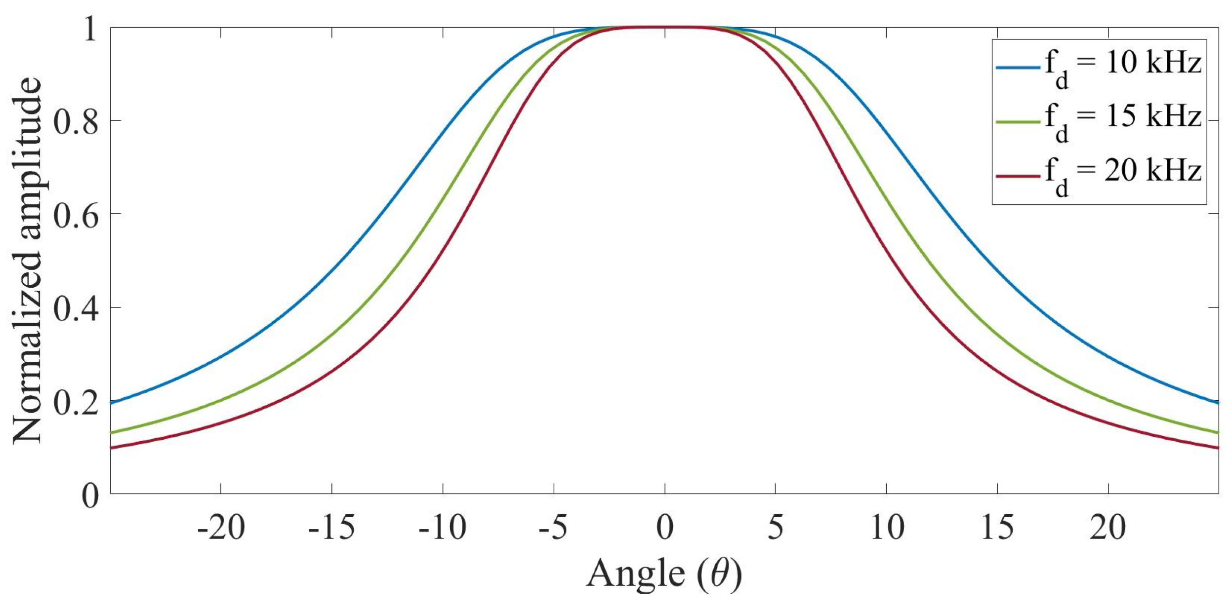
  • Directivity: The parameter f / f d sets the directivity of the parametric such that the closer the mean primary and difference frequencies are the closer the directivity of the difference frequency f d will be to f. Furthermore, for the same ratio f f d , the higher the absorption of the medium, the lower the directivity of the parametric since the primary frequency does not propagate sufficiently for the parametric f d to acquire greater directivity [27]. Figure 5 shows the directivity of parametric signals in air with a mean carrier frequency of 200 kHz and different difference frequencies of 10, 15 and 20 kHz and a transducer diameter of 33 mm.
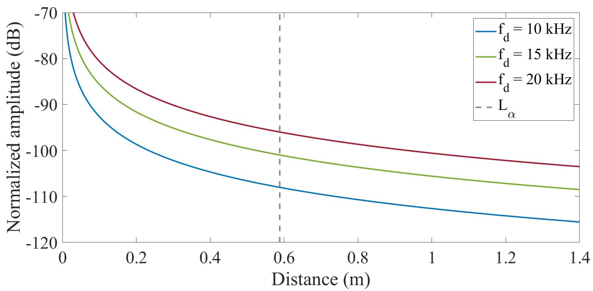
  • Attenuation: Once the parametric is formed (a necessary condition since it is a far-field solution), its attenuation is inversely proportional to the distance, which occurs with the primary beam, except that it has more absorption than the secondary beam. Figure 6 shows the behavior of the parametric with the same frequencies as in Figure 5. The gray vertical line in red marks the absorption distance for which Westervelt’s theory is applicable.

4. Experimental Set-Up

The experimental development implemented for measuring the parametric effect in air and water is presented. In both cases, the difference frequencies were f d = 10, 15 and 20 kHz. The expected parametric signals were double: f s = 20, 30 and 40 kHz. The projector or emitter was the Airmar P19 piezoelectric transducer with a resonance frequency at 200 kHz and a sensitivity in emission (Transmitting Voltage Response (TVR)) of 167 dB re μ Pa / V at 1 m . This frequency is used as the primary frequency f p . The emission surface is flat and circular with a diameter of 33 mm.
All experimental measurements were carried out to characterize the directivity and attenuation of the primary and secondary beams. The specific characteristics of the experimental setups in the two media we worked on are detailed below.

4.1. Air Measurements

These measurements were performed in an anechoic chamber; however, only the scheme for this experiment is presented since there are no photographic records of this setup, as depicted in Figure 7. The acoustic receiver used was a Behringer ECM 8000 microphone, with a flat response and a sensitivity in reception (RVR) of approximately 60 dB re V/20 µPa. The distance between the transmitter and the microphone was 90 cm.

4.2. Water Measurements

Figure 8 shows the water tank used for these measurements, the dimensions of which were 1.12 × 0.96 × 0.51 m 3 . For reception, the ITC 1032 hydrophone was used with a receiving sensitivity (RVR) of –194 dB re V/ μ Pa and a resonance frequency of 33 kHz.
In this case, the distance between the transmitter and receiver was 38 cm at the closest point. At the same time, directivity was performed by moving the hydrophone linearly perpendicular to the transducer axis so that each of the distances was subsequently corrected to obtain a reliable directivity.

5. Analysis and Results of Measurements in Air and Water

5.1. Directivity and Attenuation in Air

The difference frequencies f d used for these measurements were tone-type signals emitting at the primary frequencies shown in Table 2 at 90 c m between the emitting transducer and the microphone. According to Westervelt, these experimental results are contrasted with the theoretical nonlinearity model.
In Figure 9, it can be inferred that the experimental data fit the directivity according to the Westervelt analytical model. This is because the primary frequencies were absorbed in the medium (air), allowing the parametric to form and apply to the far-field approximation.
In this case, the primary beam was not measured since the microphone was only sensitive in the audible range up to 20 kHz. Therefore, the expected directivity of the primary beam is shown according to the expression of the flat piston [27] and that of the secondary beam, according to the Westervelt theory.
Concerning Figure 10, which presents the attenuation results, the experimental measurements for the frequencies were compared with the analytical Westervelt model (secondary beam) and the flat piston model (primary beam). It was observed that the Westervelt theory was close to the experimental data in the last measured distances since this approximation was only valid in the far field of the parametric.
From the attenuation, the pressure amplitude decreased by 6 dB as the distance doubled. Additionally, the amplitude of the parametric frequency followed a quadratic dependence with that frequency, resulting in higher pressure levels for higher parametric frequencies. However, it was essential to note that these values were influenced by the distance at which the far field was formed.

5.2. Directivity and Attenuation in Water

In these experiments, the modulation method was proposed. The tone-type frequencies used for these tests in water were the modulating frequencies f m of 10 kHz with a duration of 250 μ s , 15 kHz at 167 μ s , and 20 kHz at 125 μ s , (a doubled parametric frequency f s was expected) with a carrier frequency f p of 200 kHz. In these experiments, the sensitivity of the hydrophone made it possible to measure both the primary and secondary beams.
Figure 11 shows the directivity for these frequencies. It compares the primary and secondary beams, demonstrating that the generation of parametric signals at low frequencies (secondary beam) presents a directivity with an opening angle similar to that of the high-frequency primary beam.
Regarding attenuation, this study analyzed the generation of the secondary beam in the medium as the distance between the projector and the hydrophone changed. With an initial distance of 15 cm, the receiver moved away in steps of 4 cm until it reached a distance of 55 cm from the projector emitter.
In Figure 12, the measurements of both the primary and secondary beams are fitted to the function a x b . Neglecting absorption for a spherically propagating beam, a value of b = 1 is expected. The value for the primary beam was approximately 0.89 for all three studies; therefore, close to 1. However, the value for the secondary beam was much smaller, 0.69. This can be understood as the parametric generation of the beam in the medium, which decreases less with distance.

6. Applications to Underwater Acoustic Communications

This work used the parametric effect as a proof of concept for digital modulation on a given carrier signal, which is useful for underwater acoustic communications. The modulation used in this experiment consisted of an analog carrier modulated in amplitude by a digital modulating signal, where the most basic binary symbol was the digit 1 or 0. A generic modulation scheme includes the signals discussed below:
  • E(t): This is the modulating signal that contains the information to be transmitted.
  • y(t): Is the carrier signal that supports the frequency shift of the modulating signal; often of the sine type, i.e., y ( t ) = sin 2 π f c t .
  • x(t): Is the modulated signal resulting from the modulation process, the product of the carrier and the modulating signal; that is, x ( t ) = E ( t ) · y ( t )
This analysis started from a waveform that was suitably modulated to parametrically generate Frequency Shift Keying (FSK) coding in the medium.
Assuming that the carrier signal is an amplitude-modulated waveform and considering Berktay’s Equation (11), the proposed modulation scheme is shown in Equation (17).
x ( t ) = A p E ( t ) · sin ( 2 π f c t )
where the modulated signal x ( t ) is the result of the product of the carrier signal sin ( 2 π f c t ) and the envelope signal E ( t ) . In this study, the carrier frequency used was 200 kHz, with a sampling rate of 20 Ms/s.
To obtain the signal of interest f s parametrically, it was necessary to start from the specific expression of the desired coding; that is, the modulating signal E ( t ) = sin ( 2 π f m t ) , and by applying Equation (11), we obtained the corresponding envelope. Next, the analytical expression of the modulating signal E ( t ) was obtained through the parametric effect.

Frequency Shift Keying Modulation: Signal Processing

Frequency Shift Keying (FSK) modulation is a technique used in digital communications. It consists of an analog carrier signal, described above as y ( t ) , and a binary modulating signal E ( t ) that uses two modulating frequencies f m 1 and f m 2 , representing bits 1 and 0 [39]. The change from one frequency to the other, while maintaining a continuous phase, represents the corresponding bit change, which is combined to reproduce the desired binary code. A schematic of this modulation is shown in Figure 13.
To obtain parametric signals with this modulation, the frequencies f m 1 and f m 2 were set to half the frequencies associated with each of the bits to be received. This nonlinear acoustic technique of modulating a carrier signal with FSK produced another FSK at twice the frequency, depending on the bit to be transmitted. The mathematical expression for this modulation is given by Equation (18).
E F S K b i t 1 ( t ) = A p sin ( 2 π f m 1 ( b i t 1 ) / 2 t ) , t = t b i t 1 E F S K b i t 0 ( t ) = A p sin ( 2 π f m 2 ( b i t 0 ) / 2 t ) , t = t b i t 0
Therefore, the complete expression that parametrically determines the FKS modulation for each of the bits 1 and 0 is expressed by Equation (19).
x b i t 1 ( t ) = A p E F S K b i t 1 ( t ) · sin ( 2 π f p t ) , t = t b i t 1 x b i t 0 ( t ) = A p E F S K b i t 0 ( t ) · sin ( 2 π f p t ) , t = t b i t 0
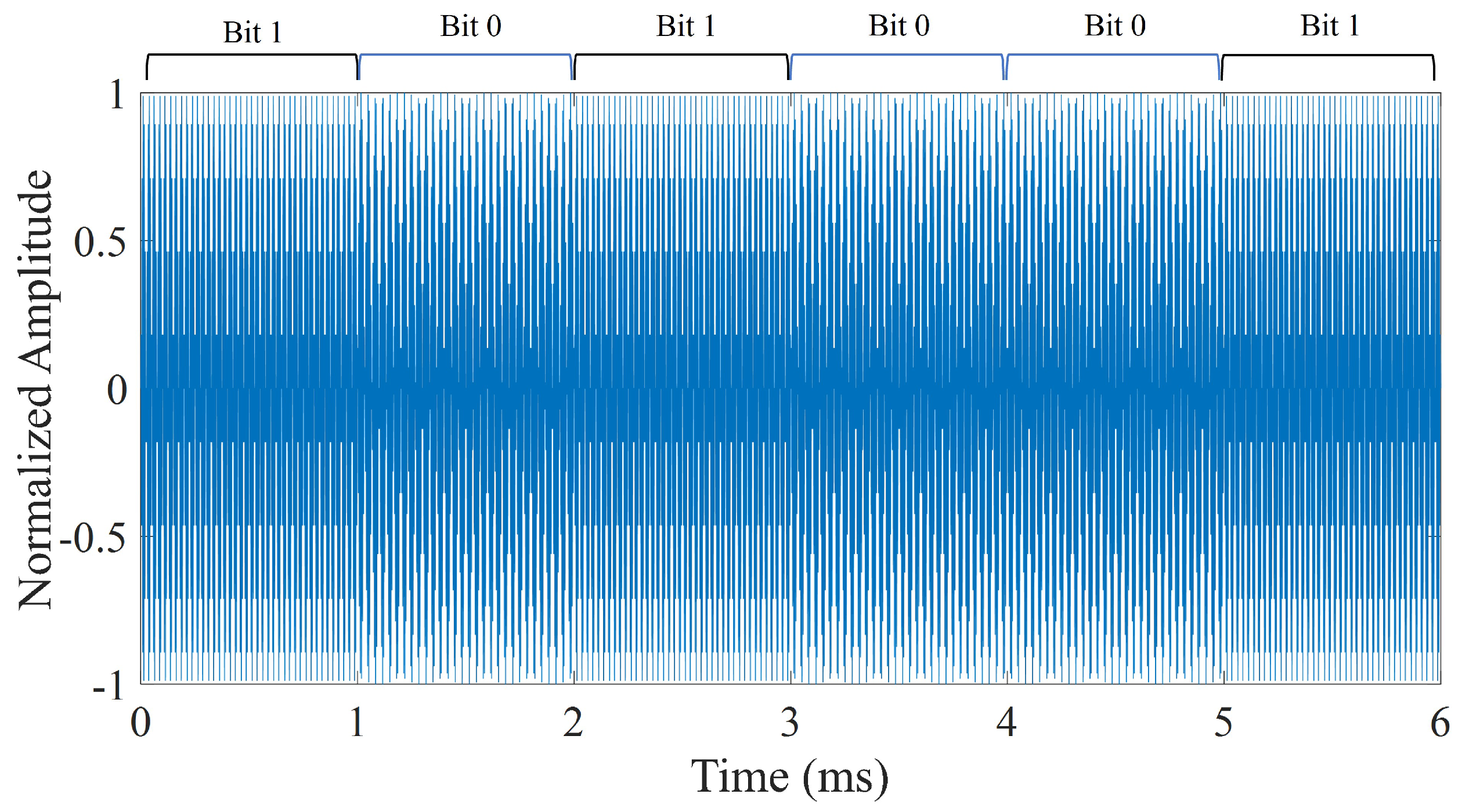
The signal processing for FSK-type nonlinear modulation was used with a carrier frequency of 200 kHz, and two modulating signals linked at half the desired parametric ( f m 1 = f b i t 1 2 for bit 1 and f m 2 = f b i t 0 2 for bit 0), which was 20 and 15 kHz, respectively, with a 1 ms duration for each bit (transfer rate of 1 kB/s).
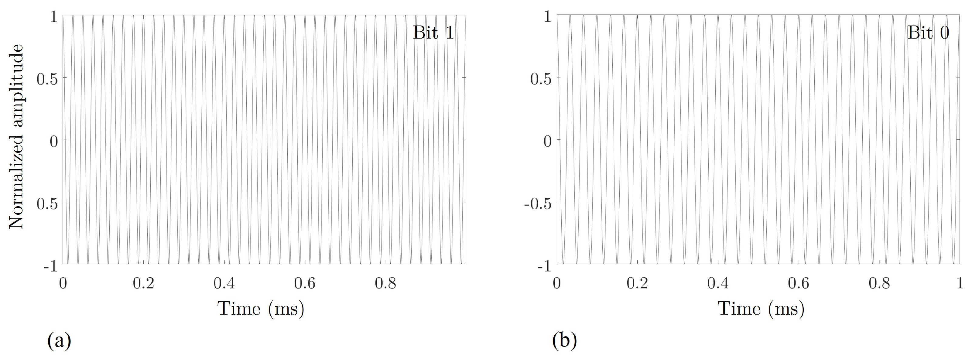
Figure 14 shows the FSK-type signal to be obtained parametrically. This consisted of two frequencies of 40 and 30 kHz.
In this work, FSK-type nonlinear modulation was achieved by using a carrier frequency of 200 kHz and the two modulating frequencies f m 1 and f m 2 as discussed above. Thus, this nonlinear technique modulated a carrier with FSK, resulting in another FSK of twice the frequency.
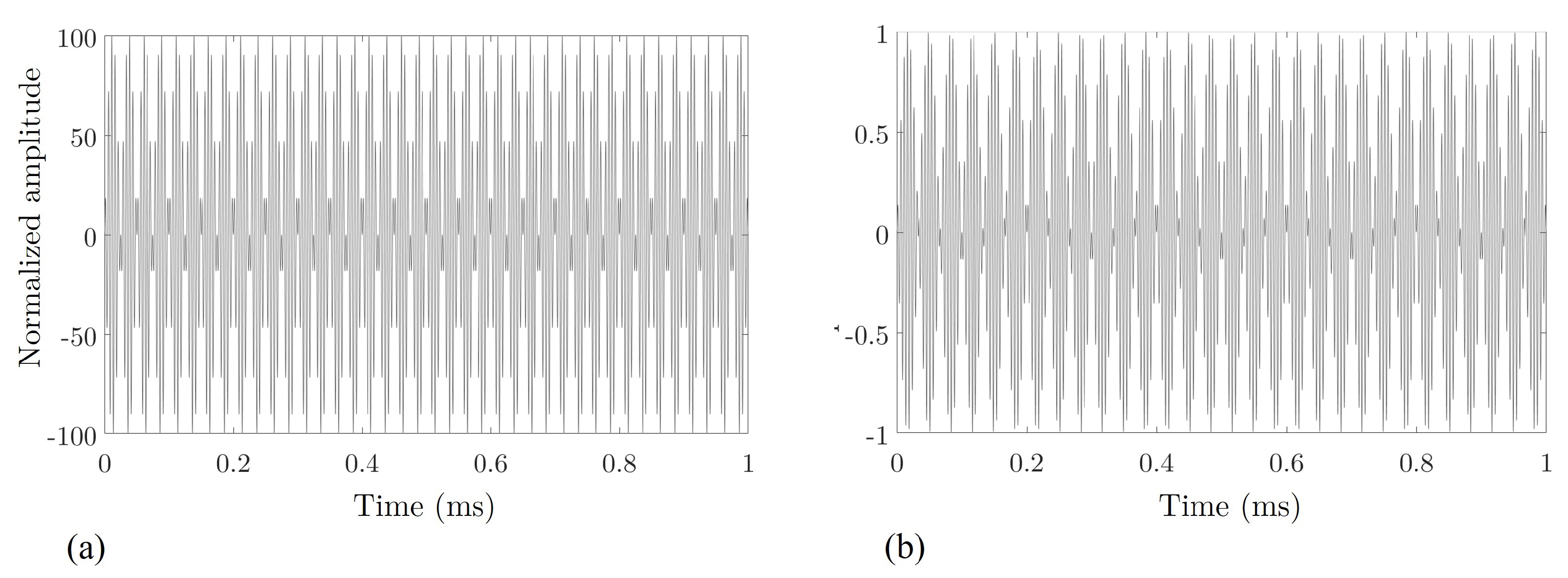
Figure 15 shows bits 1 and 0 that were sent to achieve the parametric bits of Figure 14.
Although digital modulation requires contiguous bits, these figures are presented separately for better visualization and understanding. Section 7 provides the figure for FSK-type modulation for sent coding.

7. Bit Detection by Cross-Correlation Method and Results

The low-frequency signal caused by the parametric effect had a lower amplitude than the emitted signal, which made it challenging to distinguish it from background noise. To demonstrate this empirically, it a parametric signal was recorded with a 6-bit sequence (101001). The transmitting and receiving system operated at a sampling frequency of 20 MHz, and the bits were continuously emitted. Figure 16, shows the sent FSK-type modulation emission.
The cross-correlation(or cross-covariance) method is defined as the shifted dot product between two signals and is used to quantify the degree of similarity or interdependence between two signals [40].
As predicted by the theory, these experimental results demonstrated that the parametric signal frequencies were twice those of the original signals. Cross-correlation indicated the presence of specific signals in a recording using a matched filter. This method also estimated the amplitude of the received signal [41].
It consisted of correlating a filter with an impulse response that matched the searched signal with the recorded signal. Thus, if a similarity occurred, a peak would have appeared. The technique was applied in our case by correlating the recorded signal with parametric bit signals 1 and 0.
Figure 17 shows the correlation between these bits with the FSK-type modulation.
Since the distance between the transmitter and receiver was 30 cm, the first bit was expected to be detected at 0.2 ms, and each subsequent bit was expected 1 ms later. In both correlations, the dashed line represents the expected position of bit 1 and the solid line of bit 0. Temporal precision in the detection of each bit was observed.
In addition, it was observed that the correlation peaks were quite wide (on the order of the duration of each bit, approximately) because this type of modulation was, in essence, a pure tone that changed frequency. Indeed, correlations with narrowband signals were characterized by not being very efficient in detection or temporal discrimination. However, the location of each bit was correctly obtained with a deviation of less than 1.5 % concerning the expected instant.
The average amplitudes of the correctly detected bits 1 and 0 were 7.81 × 10 5 and 3.90 × 10 5 a.u. (arbitrary units). The average amplitudes of the false bits 1 and 0 were 1.16 × 10 5 and 4.79 × 10 6 . The ratio of the correctly detected bits to false bits gave us an estimate of the bit error using the FSK technique. These values allowed us to establish a detection threshold based on the correlation amplitudes after the corresponding filtering. However, studies should be carried out to consider the variation of this bit error rate at greater distances and with greater environmental noise to establish an optimal bit detection threshold correctly.

8. Conclusions

8.1. For Measurements in Air

Westervelt’s theory was approximate when emitting with primary frequencies of 200 kHz, because at frequencies of this order, their absorption was high, which implied that in a few meters the far-field situation of the parametric would be reached, and Westervelt’s theory would be applicable.
Attenuation was lower concerning the primary frequencies. In contrast, when measured in the near field of the parametric, it presented a high level for distances close to the transducer on the order of the near field of the same, and stabilized over long distances.

8.2. For Measurements in Water

Evidence of the parametric effect on the secondary beam was also clearly shown in the directivity study, the results of which are presented in Figure 11. They show an opening angle of ±10 ° for the secondary beam, while for the primary beam it was ±9 ° with a pitch of 20 and 30 kHz, respectively. Therefore, both beams presented a similar directivity pattern despite large differences in frequency.
In contrast, for the 40 kHz frequency, the aperture angle was ±18 ° versus ±9 ° for the primary beam. Even so, if one wanted to obtain linear directivity for such a low frequency, the result would be between ±70 ° .
Regarding attenuation, these are similar to the signals studied. The amplitudes of both the primary and secondary beams decreased as the distance increased. However, the attenuation of the secondary beam for the first case (20 kHz) attenuated less than the primary frequency.
In summary, all these effects show that the signal had been parametrically generated and, therefore, this technique can be used for underwater acoustic communications in circumstances where highly directional beams are preferred. In addition, the parametric effect permits the reduction, for the most part, of the multiple reflections that can lower communication quality.

Author Contributions

Conceptualization, M.C.-V.; methodology, M.C.-V.; validation, I.R.-R. and J.-V.R.; formal analysis, M.C.-V., I.R.-R., J.-V.R. and L.-J.H.-F.; investigation, M.C.-V., I.R.-R., J.-V.R. and L.-J.H.-F.; writing—original draft preparation, M.C.-V.; writing—review and editing, I.R.-R., J.-V.R. and L.-J.H.-F.; supervision, I.R.-R., J.-V.R. and L.-J.H.-F. All authors have read and agreed to the published version of the manuscript.

Funding

This research received no external funding.

Institutional Review Board Statement

Not applicable.

Informed Consent Statement

Not applicable.

Data Availability Statement

The data presented in this study are available upon request from the corresponding author.

Acknowledgments

MaríaCampo-Valera is grateful for the postdoctoral program Margarita Salas—Spanish Ministry of Universities (financed by the European Union’s NextGenerationEU). Ignacio Rodríguez-Rodríguez would like to thank Plan Andaluz de Investigación, Desarrollo e Innovación (PAIDI), Junta de Andalucía, Spain.

Conflicts of Interest

The authors declare no conflict of interest.

References

  1. Edrich, J. 3.2. Parametric Amplifiers. In Methods in Experimental Physics; Elsevier: Amsterdam, The Netherlands, 1976; pp. 225–245. [Google Scholar] [CrossRef]
  2. Westervelt, P.J. Scattering of Sound by Sound. J. Acoust. Soc. Am. 1957, 29, 199–203. [Google Scholar] [CrossRef]
  3. Westervelt, P.J. Parametric Acoustic Array. J. Acoust. Soc. Am. 1963, 35, 535–537. [Google Scholar] [CrossRef]
  4. Berktay, H. Possible exploitation of non-linear acoustics in underwater transmitting applications. J. Sound Vib. 1965, 2, 435–461. [Google Scholar] [CrossRef]
  5. Berktay, H.O.; Leahy, D.J. Farfield performance of parametric transmitters. J. Acoust. Soc. Am. 1974, 55, 539–546. [Google Scholar] [CrossRef]
  6. Bennett, M.B.; Blackstock, D.T. Parametric array in air. J. Acoust. Soc. Am. 1975, 57, 562–568. [Google Scholar] [CrossRef]
  7. Yoneyama, M.; Fujimoto, J.; Kawamo, Y.; Sasabe, S. The audio spotlight: An application of nonlinear interaction of sound waves to a new type of loudspeaker design. J. Acoust. Soc. Am. 1983, 73, 1532–1536. [Google Scholar] [CrossRef]
  8. Pompei, F.J. Sound from Ultrasound: The Parametric Array as an Audible Sound Source. Ph.D. Thesis, Massachusetts Institute of Technology, Cambridge, MA, USA, 2002. [Google Scholar]
  9. Mellen, R.H.; Browning, D.G.; Konrad, W.L. Parametric Sonar Transmitting Array Measurements. J. Acoust. Soc. Am. 1971, 49, 932–935. [Google Scholar] [CrossRef]
  10. Mikulka, J.; Hladky, D.; Sliz, J. Parametric array as a source of audible signal. In Proceedings of the 2016 Progress in Electromagnetic Research Symposium (PIERS), Shanghai, China, 8–11 August 2016. [Google Scholar] [CrossRef]
  11. Hwang, Y.; Ahn, H.; Nguyen, D.N.; Kim, W.; Moon, W. An underwater parametric array source transducer composed of PZT/thin-polymer composite. Sens. Actuators A Phys. 2018, 279, 601–616. [Google Scholar] [CrossRef]
  12. Li, H.; Ma, J.; Zhu, J.; Chen, B. Numerical and Experimental Studies on Inclined Incidence Parametric Sound Propagation. Shock Vib. 2019, 2019, 2984191. [Google Scholar] [CrossRef] [Green Version]
  13. Zhou, H.; Huang, S.H.; Li, W. Parametric Acoustic Array and Its Application in Underwater Acoustic Engineering. Sensors 2020, 20, 2148. [Google Scholar] [CrossRef] [Green Version]
  14. Yu, S.; Liu, B.; Yu, K.; Yang, Z.; Kan, G.; Zong, L. Application of a parametric array over a mid-frequency band (4–10 kHz) –measurements of bottom backscattering strength. Ocean Eng. 2023, 280, 114914. [Google Scholar] [CrossRef]
  15. Konrad, W.L. Design and Performance of Parametric Sonar Systems. Technical Report. 1975. Available online: https://apps.dtic.mil/sti/citations/tr/ADA016242 (accessed on 20 July 2023).
  16. Pederson, T.B. A parametric sonar performance calculator. Le J. Phys. Colloq. 1979, 40, C8-137–C8-139. [Google Scholar] [CrossRef]
  17. Godø, O.R.; Foote, K.G.; Dybedal, J.; Tenningen, E.; Patel, R. Detecting Atlantic herring by parametric sonar. J. Acoust. Soc. Am. 2010, 127, EL153–EL159. [Google Scholar] [CrossRef] [PubMed]
  18. Quazi, A.; Konrad, W. Underwater acoustic communications. IEEE Commun. Mag. 1982, 20, 24–30. [Google Scholar] [CrossRef]
  19. Kopp, L.; Cano, D.; Dubois, E.; Wang, L.; Smith, B.; Coates, R. Potential performance of parametric communications. IEEE J. Ocean. Eng. 2000, 25, 282–295. [Google Scholar] [CrossRef]
  20. Tang, S.; Zhu, G.; Yin, J.; Zhang, X.; Han, X. A modulation method of parametric array for underwater acoustic communication. Appl. Acoust. 2019, 145, 305–313. [Google Scholar] [CrossRef]
  21. Wang, C.; Zhu, G.; Tang, S.; Yin, J.; Guo, L.; Sheng, X.; Li, M. Directional bionic underwater communication method using a parametric acoustic array and recursive filtering. Appl. Acoust. 2022, 191, 108665. [Google Scholar] [CrossRef]
  22. Coates, R.; Zheng, M.; Wang, L. “BASS 300 PARACOM”: A “model” underwater parametric communication system. IEEE J. Ocean. Eng. 1996, 21, 225–232. [Google Scholar] [CrossRef]
  23. Campo Valera, M.M.; Felis Enguix, I. Propiedades y aplicaciones del efecto paramétrico en aire y agua. In Proceedings of the IV Jornadas JAAS Acústica, Audio y Sonido 2018, Buenos Aires, Argentina, 15–16 August 2018. [Google Scholar]
  24. Hamilton, M.F.; Blackstock, D.T. Nonlinear Acoustics; Academic Press: San Diego, CA, USA, 1998; Volume 237. [Google Scholar]
  25. Campo-Valera, M.; Rodríguez-Rodríguez, I.; Rodríguez-Rodríguez, J. Conceptos Básicos de la Ciencia del Sonido en el Mar; UMA Editorial: Málaga, Spain, 2023; p. 104. [Google Scholar] [CrossRef]
  26. Villó-Pérez, I.; Alcover-Garau, P.M.; Campo-Valera, M.; Toledo-Moreo, R. A novel 1D-FDTD scheme to solve the nonlinear second-order thermoviscous hydrodynamic model. Commun. Nonlinear Sci. Numer. Simul. 2022, 118, 107015. [Google Scholar] [CrossRef]
  27. Kinsler, L.E.; Frey, A.R.; Coppens, A.B.; Sanders, J.V. Fundamentals of Acoustics; Universidad de California: San Diego, CA, USA, 1999; p. 560. [Google Scholar]
  28. Jiménez, V.Y. Análisis, Modelado e Igualación No Lineal de Arrays Paramétricos Acústicos. Ph.D. Thesis, Universidad Politécnica de Madrid, Madrid, Spain, 2016. [Google Scholar]
  29. Lurton, X. An Introduction to Underwater Acoustics: Principles and Applications; Springer Science & Business Media: Berlin/Heidelberg, Germany, 2002. [Google Scholar]
  30. Kite, T.D.; Post, J.T.; Hamilton, M.F. Parametric array in air: Distortion reduction by preprocessing. J. Acoust. Soc. Am. 1998, 2, 1091–1092. [Google Scholar] [CrossRef]
  31. Blackstock, D.T. Approximate Equations Governing Finite-Amplitude Sound in Thermoviscous Fluids. General Dynamics GD/E Report GD-1463-52. 1963. Available online: https://apps.dtic.mil/sti/citations/AD0415442 (accessed on 20 July 2023).
  32. Bjørnø, L. Introduction to nonlinear acoustics. Phys. Procedia 2010, 3, 5–16. [Google Scholar] [CrossRef] [Green Version]
  33. Berktay, H.O.; Shooter, J.A. Nearfield effects in end-fire line arrays. J. Acoust. Soc. Am. 1973, 53, 550–556. [Google Scholar] [CrossRef]
  34. Cervenka, P.; Alais, P. Fourier formalism for describing nonlinear self-demodulation of a primary narrow ultrasonic beam. J. Acoust. Soc. Am. 1990, 88, 473–481. [Google Scholar] [CrossRef] [Green Version]
  35. Li, S.W. Pre-processing methods for parametric array to generate wideband difference frequency signals. In Proceedings of the OCEANS 2008, Quebec City, QC, Canada, 15–18 September 2008; pp. 1–8. [Google Scholar] [CrossRef]
  36. Berktay, H.; Smith, B. End-fire array of virtual acoustic sources produced by the interaction of cylindrically spreading acoustic waves. Electron. Lett. 1965, 1, 202. [Google Scholar] [CrossRef]
  37. Garay, G. Propagación Acústica No Lineal en un Medio de Múltiple Scattering. Master’s Thesis, Universidad de la República, Montevideo, Uruguay, 2018. [Google Scholar]
  38. Campo-Valera, M.; Felis-Enguix, I.; Villó-Pérez, I. Signal Processing for Parametric Acoustic Sources Applied to Underwater Communication. Sensors 2020, 20, 5878. [Google Scholar] [CrossRef] [PubMed]
  39. Couch, L.W.; Elizondo, R.J.R.; Ruiz, J.L.C. Sistemas de Comunicación Digitales y Analógicos; Pearson Educación: London, UK, 2008; Volume 7. [Google Scholar]
  40. Oppenheim, A.V.; Schafer, R.W.; Buck, J.R. Tratamiento de Señales en Tiempo Discreto; Pearson Educación: London, UK, 2011. [Google Scholar]
  41. Adrián-Martínez, S.; Bou-Cabo, M.; Felis, I.; Llorens, C.D.; Martínez-Mora, J.A.; Saldaña, M.; Ardid, M. Acoustic signal detection through the cross-correlation method in experiments with different signal to noise ratio and reverberation conditions. In Proceedings of the Ad-hoc Networks and Wireless: ADHOC-NOW 2014 International Workshops, ETSD, MARSS, MWaoN, SecAN, SSPA, and WiSARN, Benidorm, Spain, 22–27 June 2014; Revised Selected Papers 13. Springer: Berlin/Heidelberg, Germany, 2015; pp. 66–79. [Google Scholar]
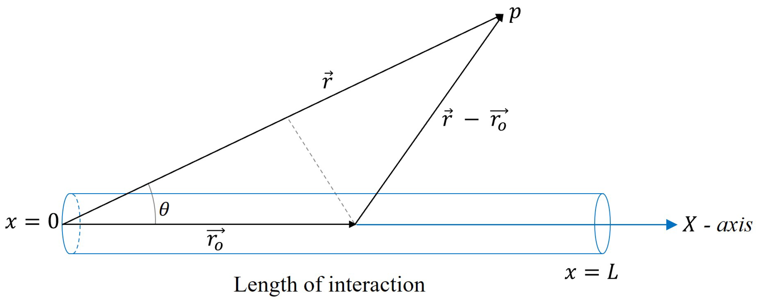
Figure 4. Geometrical configuration for interpreting the parametric effect equation [33].
Electronics 12 03459 g004
Figure 5. Theoretical directivity in air for a f d of 10, 15 and 30 kHz and a primary frequency of 200 kHz.
Electronics 12 03459 g005
Figure 6. Theoretical attenuation in air for a f d of 10, 15 and 30 kHz f d and a primary frequency of 200 kHz.
Electronics 12 03459 g006
Figure 7. Schematic of the experimental setup for parametric measurements in air in an anechoic chamber.
Electronics 12 03459 g007
Figure 8. Experimental measurements of parametric signals in a water tank. (a) Scheme of the experimental setup; (b) A photograph of the experiment with a transmitter-receiver distance of 38 cm.
Electronics 12 03459 g008
Figure 9. Parametric directivity emitted with the Airmar P19 transducer in air. The figures show the theoretical and experimental secondary beams compared to the theoretical primary frequency. (a) 20, (b) 30, (c) 40 kHz.
Electronics 12 03459 g009
Figure 10. Parametric attenution emitted with the Airmar P19 transducer in air. The figures show the theoretical and experimental secondary beams compared to the theoretical primary frequency. (a) 20, (b) 30, (c) 40 kHz.
Electronics 12 03459 g010
Figure 11. Parametric directivity measured the Airmar P19 transducer in the water, the secondary beam is compared with the primary beam. (a) 20, (b) 30, (c) 40 kHz.
Electronics 12 03459 g011
Figure 12. Parametric attenuation emitting with Airmar P19 transducer in water, secondary beam compared to the primary beam. (a) 20, (b) 30, (c) 40 kHz.
Electronics 12 03459 g012
Figure 13. Schematic representation of FSK modulation.
Electronics 12 03459 g013
Figure 14. Obtaining the FSK-type signal parametrically. (a) Bit 1 represents 40 kHz of the modulating signal; (b) Bit 0 represents 30 kHz of the modulating signal.
Electronics 12 03459 g014
Figure 15. FSK-type modulation emitted with a carrier frequency of 200 kHz and two modulating frequencies of 20 kHz and 15 kHz. (a) Bit 1, 20 kHz; (b) Bit 0, 15 kHz.
Electronics 12 03459 g015
Figure 16. FSK-type modulation emitted with the 6-bit sequence 101001.
Electronics 12 03459 g016
Figure 17. Cross-correlations. (a) Between the signal received at 40 kHz and the expected bit 1; (b) Between the signal at 30 kHz and the expected bit 0.
Electronics 12 03459 g017
Table 1. List of variables.
VariablesDescription
f d Difference frequency
L S Shock distance
c o Small-signal sound speed
β Nonlinearity coefficient
B / A Nonlinear parameter
λ p Wavelength of the primary frequency
kWave number
MMach number
vLocal wave velocity
L A Absortion length
α Attenuation coefficient
L R Rayleigh distance
aDiameter of the active zone of the emitting transducer
Partial derivative
ρ Absolute mass density
u Absolute velocity vector
pAbsolute pressure
μ b Bulk viscosity
μ Shear viscosity
p , ρ , s Acoustic quantities
p s ( r ) Pressure distribution of the parametric frequency
p p ( x , t ) Pressure wave of the primary wave
f c Carrier frequency
E ( t ) Envelope defined by the modulating wave
f s Parametric frequency (twice of the f d )
p d ( r , θ ) Acoustic field of the difference frequency
x ( t ) Digital modulation
Table 2. Difference frequencies used for measurements in air together with expected parametric frequencies.
Primary Freq. (kHz)Difference Freq. (kHz)
f d = f 1 f 2
Secondary Freq. (Param)
(kHz)
f 1 a = 197, f 2 a = 2071020
f 1 b = 195.5, f 2 b = 209.5∼1530
f 1 c = 190, f 2 c = 2102040
Disclaimer/Publisher’s Note: The statements, opinions and data contained in all publications are solely those of the individual author(s) and contributor(s) and not of MDPI and/or the editor(s). MDPI and/or the editor(s) disclaim responsibility for any injury to people or property resulting from any ideas, methods, instructions or products referred to in the content.