Abstract
Energy harvesting systems are key elements for the widespread deployment of wireless sensor nodes. Although many energy harvesting systems exist, electric field energy harvesting is a promising choice because it can provide uninterrupted power regardless of external conditions and depends only on the presence of AC voltage in the grid, regardless of the magnitude of the line current, even under no-load conditions. However, it also has some disadvantages, such as low power availability, the need for storage, or reliance on capacitive coupling, which is a complex phenomenon that depends on parasitic capacitances. This paper aims to provide useful and practical information on the possibilities of electric field energy harvesting for both high- and low-voltage applications. Since the objective of this paper is to quantify the physical limit of the harvested energy, it considers only the physical harvester itself and not the electronic circuitry required to transfer the harvested energy to the load. Theoretical, simulation, and experimental results show the feasibility of this energy source for low-power applications such as wireless sensor nodes.
1. Introduction
Today, wireless sensors are being used to monitor low- and high-voltage utility assets and power lines. Because these sensors operate autonomously without a grid connection, most are powered by electrochemical batteries, which are costly and often difficult and impractical to replace. Therefore, there is a need for self-powered, wireless sensor nodes that are more environmentally friendly and minimize the costs associated with periodic maintenance. Energy harvesting (EH) offers a potential solution to this problem, as this technology enables the conversion of ambient energy into electrical energy [1]. This harvested energy can be stored in electrochemical batteries or capacitors for later consumption or used directly [2]. It has been shown that electronic systems requiring average power levels between 200 μW and 10 mW can be powered by energy harvesting systems from ambient sources [3]. There are many ways to harvest energy from ambient sources, such as thermal energy harvesting [4,5], solar [6], vibration [7], radio frequency [2], piezoelectric [8], magnetic field [9], or electric field [1], among others.
Electric field energy harvesting (EFEH) is a promising technology because it can provide reliable and continuous power with the only condition that the line is energized, regardless of the magnitude of the line current, even under no-load conditions. Since the line frequency and voltage are tightly controlled, the expected power production can be accurately predicted, and it is easy to install and implement [2,10], so the use of batteries is not mandatory. Although most energy harvesting systems today use auxiliary batteries, they require periodic replacement due to their finite lifetime and generate waste, so batteryless systems are needed. Due to the characteristics of batteryless energy harvesting systems, they allow electronic sensors to be deployed in remote or inaccessible regions while contributing to the reduction of the carbon footprint [2]. However, EFEH also has some drawbacks, such as low power availability, so there is a need for storage. EFEH relies on capacitive coupling, which is a complex phenomenon, so the parasitic capacitances can affect the power output. Finally, size constraints could also limit the power output [10], especially for low-voltage applications.
It is well known that any energized conductor generates a radial electric field, which is a potential source of energy. In AC systems, there is a capacitive displacement current between the energized conductor and the ground through the surrounding air that can charge a nearby capacitor, so that the energy stored in that capacitor, EC, can be expressed as half the product of its capacitance and the square of its voltage. An electric field harvester is designed to capture some of this energy [1]. The electric field generated by a transmission line is independent of the amount of current, as it depends only on the voltage applied. Therefore, EFEH is the only method that can provide effective EH at any time the line is energized, even when it is not carrying current. This makes electric field EH the most viable option for powering sensors in terms of predictability, availability, and controllability [10]. The idea of harvesting energy from the electric fields is not new [11]. Unlike many conventional harvesting methods, EFEH is almost independent of environmental variables [12], making it more durable and reliable. It can operate on any conductive material to which a voltage is applied, making it ideal for applications that require a certain quality of service. Because the frequency and voltage of transmission lines are tightly regulated, the electric field they generate is stable, allowing predictable amounts of energy to be harvested due to the constant rate of power harvesting [10]. Electric field EH is well suited for high-voltage transmission lines due to the strong electric fields associated with them, although various works have shown that it is also feasible in low-voltage applications [13,14] using low-power electronics and switches.
In most cases, due to the scarce energy scavenged by the EH unit, EH-based systems typically operate in an intermittent on-off pattern [15,16]. Since the device communicates cyclically with a gateway, communication protocols typically present different communication phases (advertising parameter initialization, advertising start, transmission, delay, and sleep) that exhibit a cyclic load profile [16]. Due to these constraints, the EH unit typically requires an electronic circuit that includes diodes to rectify the generated voltage and prevent the harvested energy from being fed back, storage capacitors or supercapacitors, and a controlled switch to regulate the energy usage. The switch allows the capacitor to be automatically charged when the voltage is below a certain level and connects the capacitor to the load when the stored energy is high enough for transfer. To save energy, EH-based systems are typically programmed to operate in low power mode during the sleep phase, when the capacitor is charging. When the capacitor is sufficiently charged, it transfers the energy to the rest of the circuit, which is activated. Therefore, it is essential to use high-efficiency rectifiers, microcontrollers, and regulators to optimize the overall efficiency of the energy harvester [10]. The efficiency of the circuit that controls the charging and discharging of the capacitor is a key point, as it can range from about 3% to >90% [17].
Several EFEH approaches can be found in the technical bibliography. In [18], a wire wound around an insulated single-phase 3-wire 220 V cable was used to harvest energy from the stray electric field, generating an average of 680 nW. In [10,19], an EFEH system is proposed using a dielectric layer and a conductive sheath wound around the conductor, generating a stray capacitance that is used to harvest energy from the electric field generated by the conductor. A multilayer structure is also possible. A similar approach was applied in [14], using a 220 V power line as a reference, showing an average extracted power of about 47 μW. In [1], using a copper sheet wrapped around a 230 V power line, the authors harvested 367.5 μW. In [20], a similar EFEH method was applied using a power line insulator, and the authors state that up to 17 mW of continuous power can be extracted from a 12.7 kV medium-voltage power line. Similar circuits can be applied using metal plates instead of wrapping a conductive sheath around the conductor [18,21]. In [22], it is shown that 2.5 µW can be extracted from a 120 V power line using a metal plate. A similar approach is proposed in [23], which shows that a displacement current of fractions of mA can be induced.
Most of the papers found in the technical literature focus on a specific application in the low or high voltage range or analyze specific impedance matching circuits to optimize the extraction of energy from the physical harvester element. This paper, however, aims to generalize and provide useful information to practitioners about the physical limits of EFEH for both low- and high-voltage applications. Since the objective of this paper is to determine the physical limit of the harvested energy, it considers only the physical harvester itself and not the circuitry required to transfer the harvested energy to the load. Therefore, this paper does not analyze the different possibilities of switching circuits since there are different possible strategies that will be studied and evaluated in a paper. This paper also develops a theoretical analysis and presents simulation and experimental results, showing the feasibility of this technology to supply low-power wireless sensor nodes.
2. EFEH for Low-Voltage Multicore Insulated Wires
This section discusses how to harvest energy from the electric field around low-voltage insulated wires.
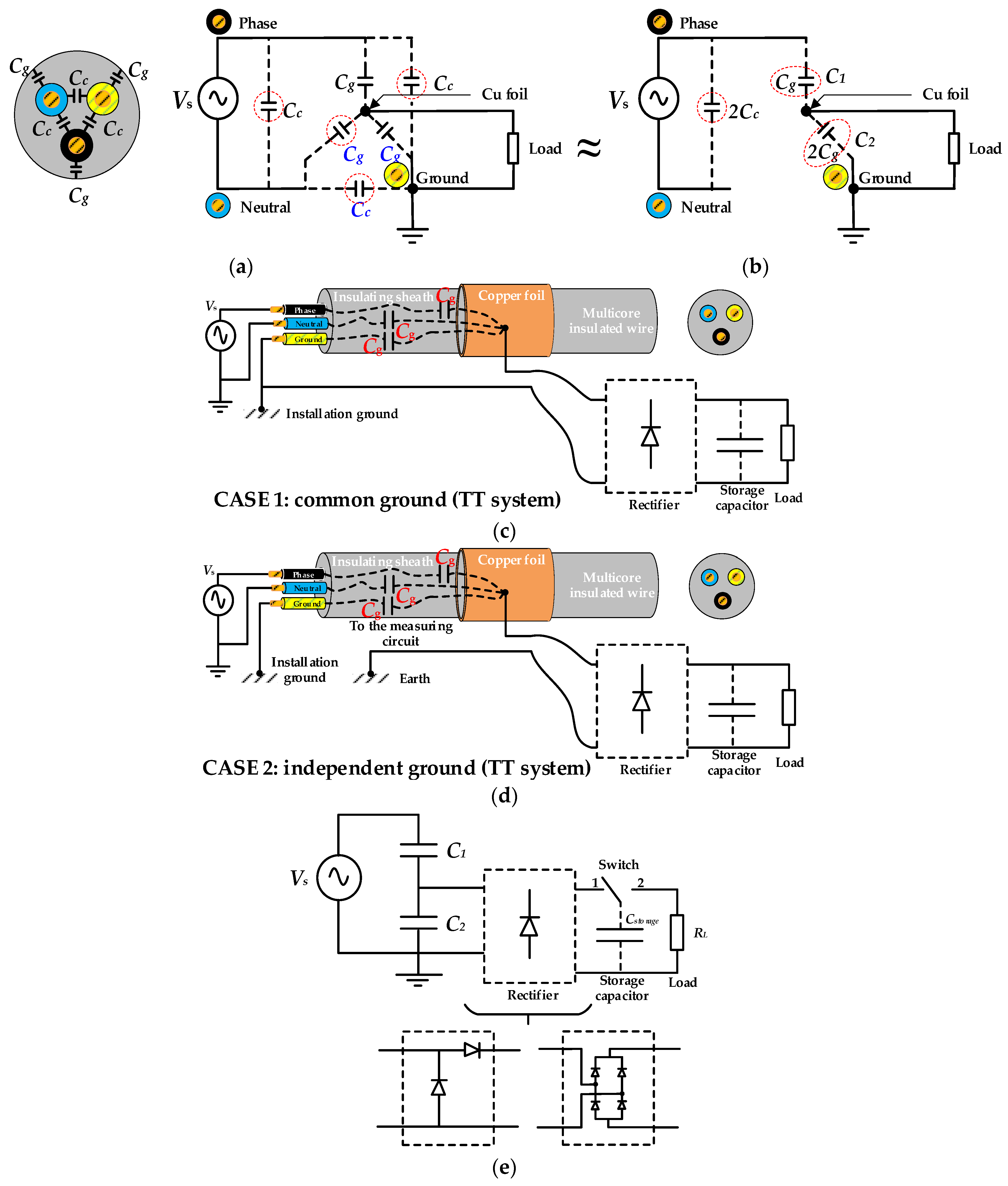
Figure 1 shows the basic configuration of the low-voltage insulated wire energy harvester. To harvest energy from the surrounding electric field, the multi-conductor insulated wire is covered with a thin copper foil. While the conductor of the hot wire acts as the inner electrode, the copper foil acts as the outer electrode. While Cc is the capacitance between two wires, Cg is the capacitance between one wire and the copper foil. Due to the symmetry of the layout shown in Figure 1, all Cc capacitances are identical, as well are all Cg capacitances.
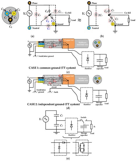
Figure 1.
(a) Capacitances of a multicore insulated wire covered with a thin copper foil. (b) Equivalent circuit. (c) Multicore insulated wire, harvester and load with common ground. (d) Multicore insulated wire, harvester and load with independent ground. (e) Simplified diagram with half-wave and full-wave diode rectifiers, controlled switch and load.
In TN and TT grounding systems, the ground and neutral wires are almost at the same potential, so the layout presented in Figure 1b is equivalent to that shown in Figure 1a. Note that since the capacitance 2Cc is connected in parallel with the AC supply, it does not change the voltage seen by the series connection of C1 = Cg and C2 ≈ 2C1. Capacitances C1 and C2 are in the order of 100–200 pF, so for resistive loads below 1 MΩ, the capacitance C2 has very little effect on the voltage in the load resistance; only the top capacitance C1 in Figure 1b affects the voltage across the load terminals. The values of capacitances C1 and C2 can be determined from experimental measurements, as shown in Section 4.
Due to the presence of the parasitic capacitances C1 and C2, the surrounding copper foil behaves as a voltage source due to the displacement current generated by this configuration, so it can be used for energy harvesting purposes [13]. This cylindrical harvester configuration is equivalent to a capacitive voltage divider.
The voltage generated by the energy harvester can be rectified using a two-diode rectifier or a four-diode full-wave rectifier, the former being the simplest and most effective solution. In this way, it is possible to charge a storage capacitor while preventing it from discharging through the rest of the circuit. Due to the reduced power generated by the harvester, IoT devices can typically use an intermittent strategy. Energy is generated and stored in the storage capacitor, and when there is enough energy, the sensor and communication systems are activated.
According to Figure 1, when a purely resistive load is connected directly in parallel with C2, the AC output voltage Vout across the load resistor RL is determined as follows:
When a purely resistive load RL is directly connected in parallel with C2, the voltage Vout between the terminals of the load can be obtained as follows:
where Vs is the supply voltage, as shown in Figure 1.
Therefore, when RL is infinite, Vout results in the expression of a capacitive voltage divider:
In Section 4, it is shown that for the geometry analyzed in Figure 1 C1 ≈ 0.5C2. From (3), it follows that Vout ≈ Vs/3.
Assuming a purely resistive load RL, the output power can be calculated as
The optimum value of the load resistance to obtain the maximum output power can be obtained by deriving the output power in (4) with respect to RL, which gives:
Finally, by combining (4) and (5), the maximum power transferred to the load becomes:
According to [11], the effective power that can be transferred to the load can be calculated as
As shown in Figure 1e, a capacitor Cstorage can be added to store energy for later use by the electronic circuit. However, a diode rectifier is required to charge the capacitor, which reduces the power given by (4) [1]. To increase the output power and shorten the discharge time, the EFEH system requires a switching circuit, as shown in Figure 1b,c [1]. When the voltage across the terminals of Cstorage is below a threshold value (charge stage). Otherwise, when the voltage across the terminals of Cstorage is sufficient, the switching circuit disconnects Cstorage from the harvester and connects it to the load (discharge stage). The energy released by Cstorage is used to power the sensors, electronics, and communication module, gradually discharging it until the voltage threshold is reached. The switching circuit then disconnects Cstorage from the load and reconnects it to the harvester in a cyclic mode.
The amount of energy stored Estored in the capacitor and extracted from the harvester can be calculated as follows:
where V is the voltage in the storage capacitor. Assuming that during the transmission phase of the communication circuit, the capacitor discharges from V1 to V2, where V2 < V1, the energy released from the capacitor is as follows:
Therefore, the corresponding power dissipated by the storage capacitor between two times t1 and t2 can be calculated as [19]
From (8)–(10), it can be deduced that the size of the storage capacitor and its maximum voltage greatly influence the energy it can store, but at the expense of longer charging times, which limits the communication rate of the entire electric field EH system.
3. EFEH for High-Voltage Overhead Power Lines and Substation Bus Bars
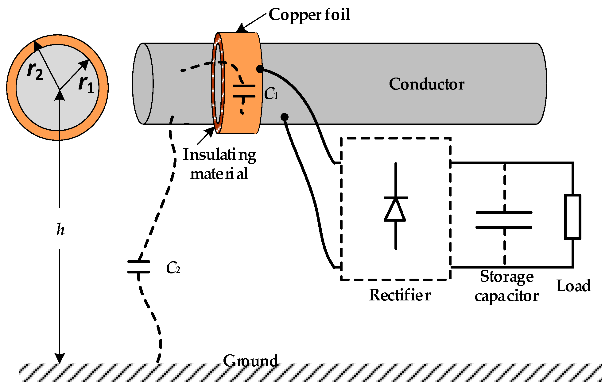
Figure 2 shows the basic configuration of the energy harvester for high-voltage overhead power lines and substation bus bars. This cylindrical harvester also acts as a capacitive voltage divider. While C1 is the capacitance of the cylindrical shell, C2 is the leakage capacitance to ground. The conductor acts as the inner electrode, which is wrapped by a thin layer of an insulating or dielectric material covered by a thin copper foil, which acts as the outer electrode.

Figure 2.
Electric field energy harvester for high-voltage overhead power lines.
It should be noted that although a full-wave diode rectifier can be used, experimental results show that the voltage at the load resistor is almost the same as that obtained with a half-wave diode rectifier. Therefore, the latter rectifier will be used in the remainder of this document. It is known that the capacitance of a cylindrical capacitor with inner and outer radius r1 and r2, respectively, can be calculated as [17,24]
where ε0 = 8.854 × 10⁻¹² F/m is the permittivity of free air, εr [-] is the relative permittivity of the insulating material, L [m] is the axial length of the harvester, and r1 and r2 are the radii of the inner and outer electrodes, respectively.
The capacitance to ground of a cylindrical conductor of infinite length is determined as [25]
According to Figure 2, when a purely resistive load is connected directly in parallel with C1, the AC output voltage Vout across the load resistor RL is determined as follows:
where Vs is the voltage of the source and ω = 2πf is the angular frequency of the line.
The voltage Vout at the terminals of the load RL is given by
When RL is infinite, Vout gives the expression of a capacitive voltage divider so that the voltage induced across the terminals of C1 is given by
Section 4 shows that for overhead power lines, C1 >> C2, 1/(ωC1) << 1/(ωC2) so that the current flowing through the leakage capacitors C1 and C2 is largely determined by C2; C1 has little influence, and the value of Vout is a small fraction of the value of Vs.
The module of Vout can be obtained as
The output power at the load RL can be determined as
According to (17), to maximize the power at the load impedance, its value must be increased as much as possible [19]. Therefore, special care must be taken to select a specific transmission system with very low energy consumption (high impedance), especially during sleep mode when the storage capacitor must store the energy for the different communication phases. Smart devices often communicate cyclically with a nearby gateway, so the energy consumption has a cyclic profile consisting of five modes (advertisement parameter initialization, advertisement start, transmission, delay, and sleep) [26].
The optimal value of the load resistance to obtain the maximum output power is [1] and can be obtained by deriving the output power in (17) with respect to RL, which results in
Finally, by combining (17) and (18), the maximum power transferred to the load is given by
It is worth noting that the maximum power that can be extracted from the harvester increases linearly with the supply frequency and quadratically with the voltage of the source and with the value of C2, since C1 >> C2.
4. Experimental Results
4.1. Experimental and Simulation Results with the Low-Voltage Multicore Insulated Wire
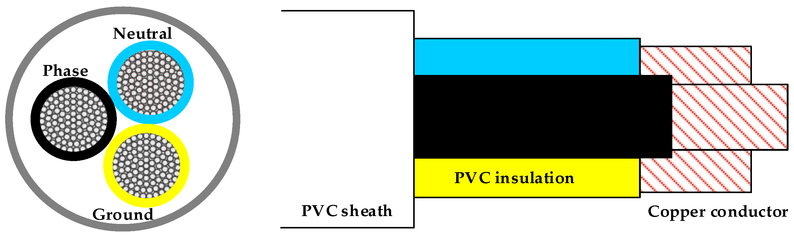
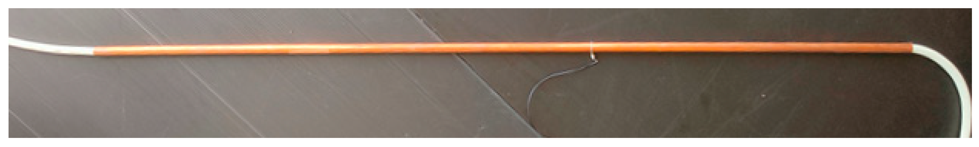
The tested low-voltage multicore insulated wire (3 × 2.5 mm2, PVC insulation, TOPFLEX VV-F H05VV-F, TopCable, Rubí, Barcelona, Spain) has an external diameter of 9.80 mm and is composed of 3 wires of 2.5 mm² each (diameter = 2.4 mm each). Figure 3 shows the low-voltage multicore insulated wire.
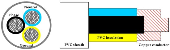
Figure 3.
Analyzed low-voltage multicore insulated cable.
Figure 4 shows the low-voltage multicore insulated wire and the copper foil required to build the harvester.

Figure 4.
Harvester for the low-voltage multicore insulated wire with an external copper sheet 1 m long.
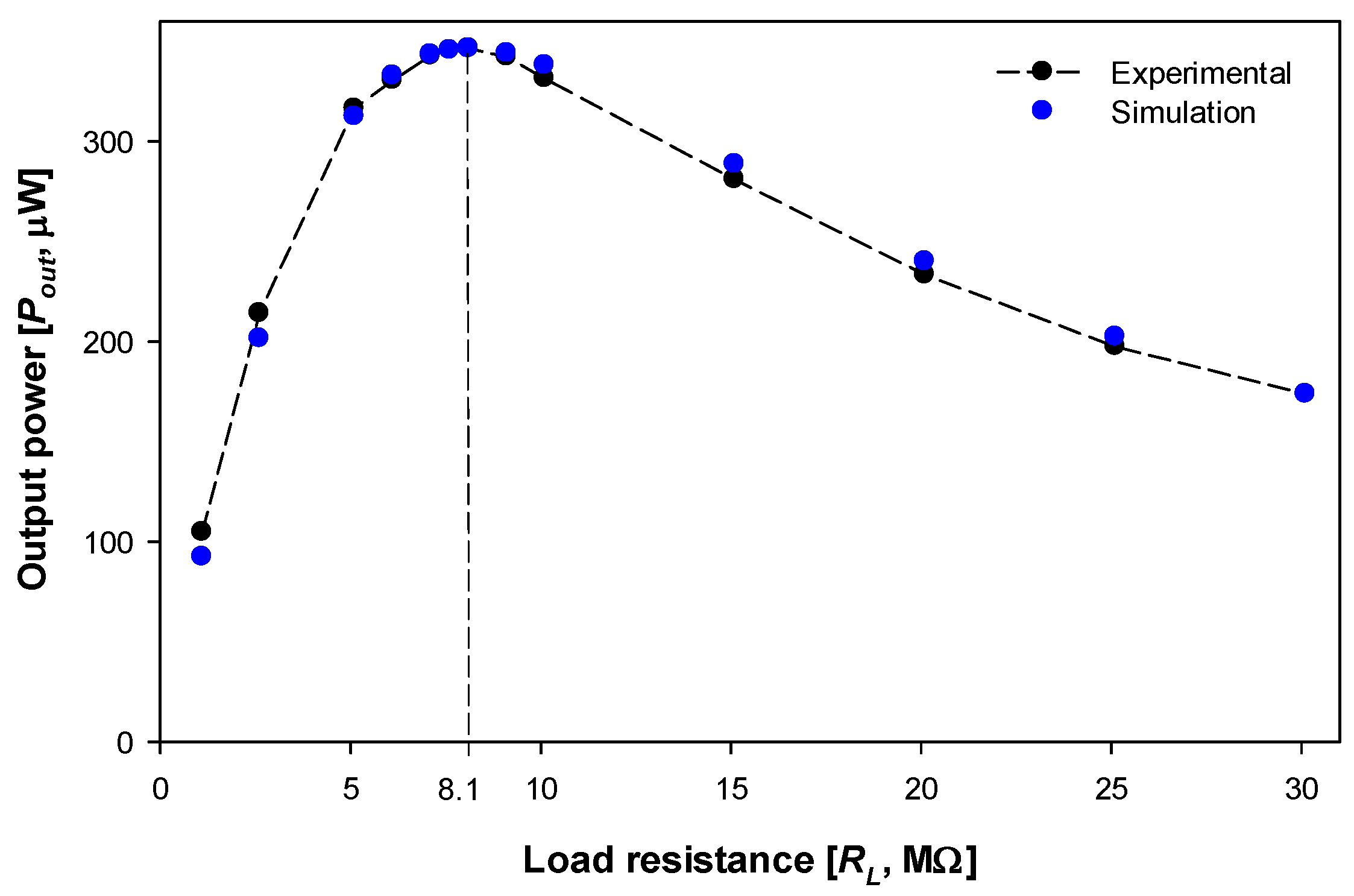
The following procedure is used to experimentally determine the capacitances C1 and C2. Various resistors are connected directly in parallel with C2 as shown in Figure 1c, without the rectifier and Cstorage. The experimental values of the load resistances and the AC output power of the load are shown in Figure 5. The experimental optimum value of the load resistance is about 8.1 MΩ, which gives a maximum output power in the load of 346.5 μW at 230 V. This means that this energy harvester can only supply ultra-low-power devices. Next, the maximum of the RL–Pout graph is located, so that the values of C1 and C2 are determined from (17) and (18) as follows:
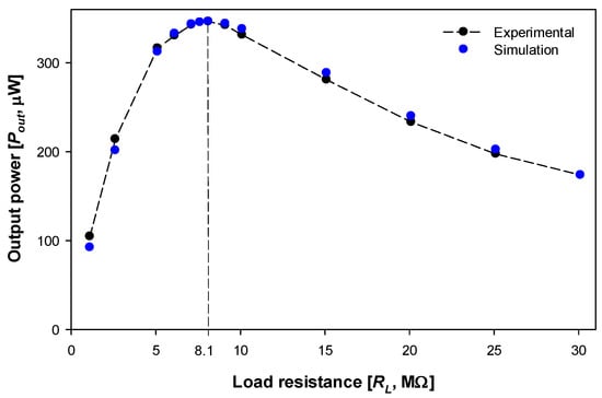
Figure 5.
Experimental results in common ground configuration with a 100 cm long harvester. Relationship between the harvested power and the load resistance RL when it is directly connected to C2.
Figure 5 shows experimental measurements of the power generated by the low-voltage energy harvester when various purely resistive loads are connected directly to the harvester’s terminals. It also shows the simulation performed in LTspice version 17.1.8 with the layout shown in Figure 1e without the rectifier and Cstorage using the calculated values C1 = 128 pF and C2 = 265 pF.
Table 1 shows the experimental results obtained with a 100 cm long harvester by connecting various load resistances directly in parallel with C1 (without the diode rectifier and storage capacitor). The simulations assume C1 = Cg = 128 pF and C2 ≈ 2Cg = 265 pF. Note that two harvesters of 30 cm and 100 cm have been tested and proportional results have been obtained, i.e., the voltage at the load follows the pattern VL,30cm = 30VL,100cm /100.

Table 1.
Experimental and simulated results at Vs = 115 V-RMS and Vs = 230 V-RMS. The length of the copper foil is 100 cm.
The values shown in Table 1 were corrected to compensate for the effect of the internal impedance of the multimeter (Fluke 289, input impedance 10 MΩ < 100 pF, Fluke, Everett, Washington, DC, USA). These results show that the harvested voltage increases almost linearly with the value of the load resistance. The results in Table 1 also confirm the dependence of the harvested voltage on the supply voltage, as the amplitudes of the harvested voltages at 230 V-RMS are approximately twice those at 115 V-RMS. It should be noted that when the harvester is connected to an independent ground, the output voltage is reduced to approximately half of that obtained with a common ground.
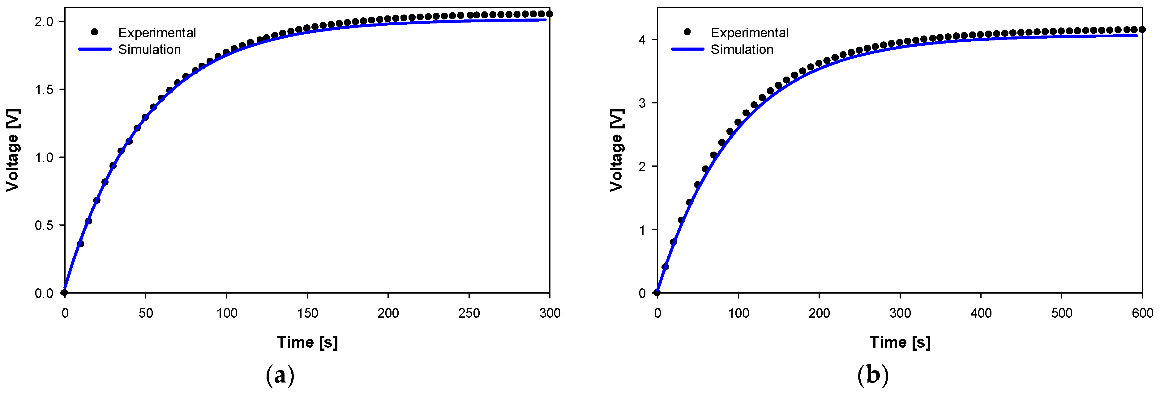
Next, the load resistance was fed through the two-diode rectifier and a 0.1 mF tantalum storage capacitor, as shown in Figure 1b. The experimental and simulated results obtained with Vs = 230 V-RMS are shown in Figure 6. The simulations were performed in LTspice version 17.1.8 with the layout shown in Figure 1e.
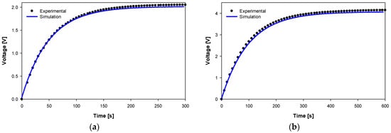
Figure 6.
Experimental results at 230 V-RMS with two-diode rectifier, 0.1 mF capacitor and load resistor assuming C1 = Cg = 128 pF and C2 = 265 pF. (a) Rload = 0.5 MΩ. (b) Rload = 1 MΩ.
The results shown in Figure 6 show the great similarity between the experimental and simulated results, thus validating the simple model presented in Figure 1.
The experimental and simulation results presented in this section show that the voltage across the load terminals is directly proportional to the source voltage. When a rectifier and a storage capacitor are added, the load voltage is also almost independent of the value of Cstorage. However, for a given resistive load, the time required to charge the capacitor increases with the product τ = RL·Cstorage, where τ [s] is the time constant.
4.2. Experimental and Simulation Results with High-Voltage Power Lines and Substation Bus Bars
4.2.1. Calculation of the Capacitances C1 and C2
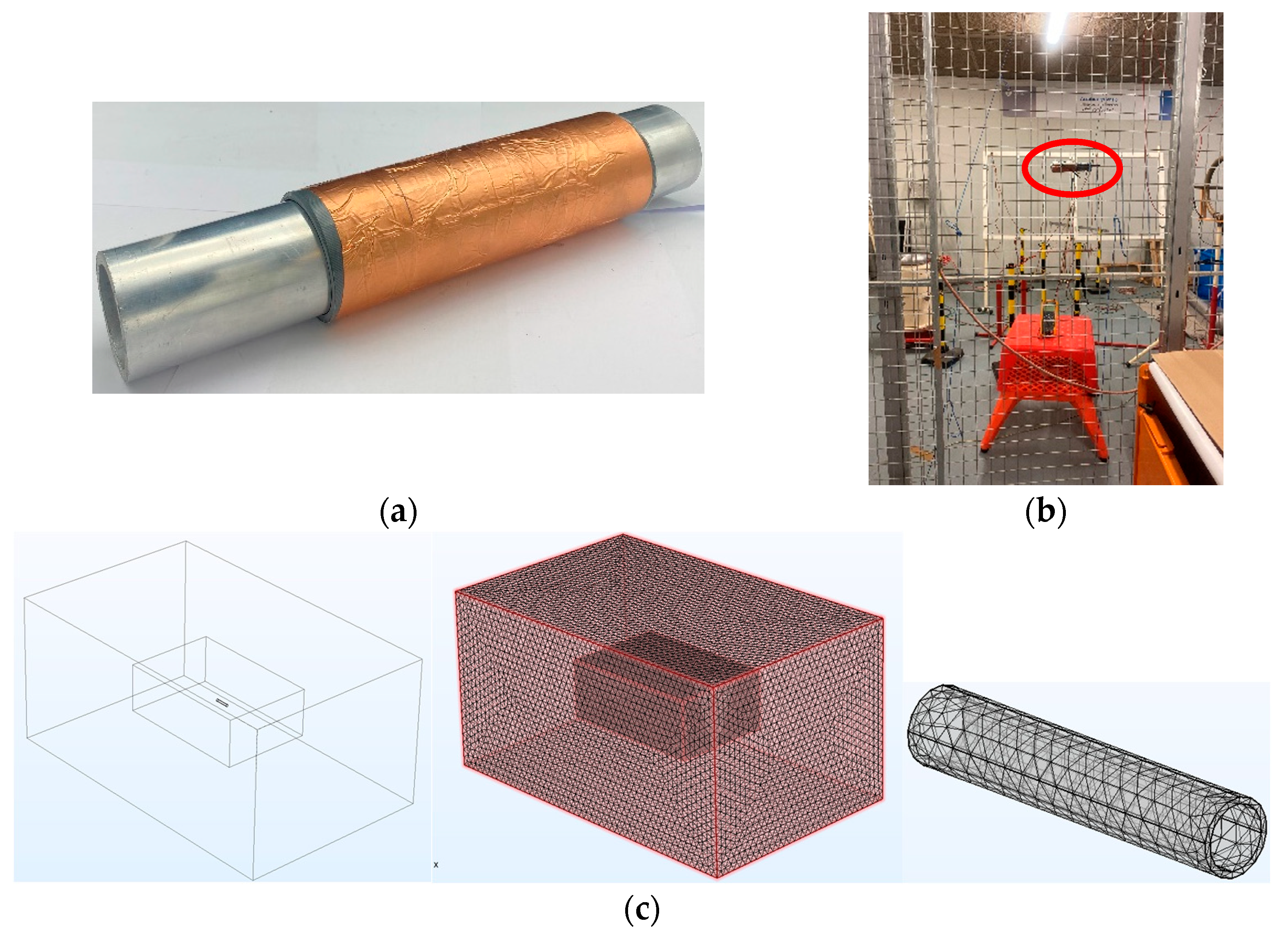
Figure 7 shows the tubular aluminum bus bar and the physical harvester made of silicone rubber and a copper foil, the harvester placed in the high-voltage laboratory, and the Comsol Multiphysics FEM simulations performed to determine the stray capacitance to ground C2 (see Figure 2).

Figure 7.
(a) Cylindrical harvester for the bus bar. The tubular aluminum bus bar used in the experiments has an outer radius of 25 mm, an inner radius of 22.4 mm, and a length of 300 mm. (b) Photograph of the bus bar and the harvester in the high-voltage laboratory. (c) Comsol Multiphysics FEM geometry, including the high-voltage laboratory geometry (length = 7.1 m, width = 4.4 m and height = 3.1 m with the conductor at a height of 1.5 above the ground plane), with an inner box for a finer mesh and the cylindrical bus bar (outer radius of 25 mm, inner radius of 22.4 mm and length of 300 mm). The three-dimensional mesh contains 262,636 vertices, 1,543,283 tetrahedra, 37,442 triangles, and 11,112 edge elements.
A thin layer of insulating material (εr = 3.2, length = 170 mm, thickness = 3.5 mm) was wrapped around the tubular bus bar (inner electrode). The insulating material (silicone rubber) was covered with a thin copper foil acting as the outer electrode, as shown in Figure 7a. Equation (11) was used to calculate the value of C1, with εr = 3.2, L = 0.17 m, r1 = 0.025 m, and r2 = 0.0285 m, resulting in C1 = 230.97 pF. The capacitance was then measured with the LCR precision bridge, which gave C1 = 228.29 pF, so a value of C1 = 230 pF is used for calculation purposes, which at a line frequency of 50 Hz gives a reactance of 13.84 MΩ.
The tubular busbar was placed horizontally at a height h = 1.5 m above the ground plane. Due to the geometry shown in Figure 2, there are no analytical equations to determine C2, so FEM simulations are required for this purpose. These simulations yield a value of C2 = 8.5 pF, which corresponds to a reactance of 370.1 MΩ at 50 Hz.
According to (18) and (19), the theoretically optimal value of the load resistance for the configuration considered in this paper is 13.35 MΩ, which gives 19.0 mW at 20 kV and 119.0 mW at 50 kV, although a load resistance of this value is impractical. In a previous study [26], it was shown that a smart device for high-voltage power lines based on Bluetooth Low Energy (BLE) communication consumes about 5 uA at 2.55 V in sleep mode, thus resulting in a load resistance RLoad ≈ 0.5 MΩ. Therefore, in this section, this value is considered the reference load resistance during the storage capacitor charging phase. For values of RLoad below 0.5 MΩ, the result of paralleling C1 and RLoad is almost RLoad, so the influence of C1 in the results is very small, but according to (16) and (17), the influence of C2 is very important.
4.2.2. Experimental and Simulation Results with the High-Voltage Cylindrical Bus Bar
This section describes the results obtained in the high-voltage laboratory, whose dimensions are length = 7.1 m, width = 4.4 m and height = 3.1 m. The aluminum tubular bus bar shown in Figure 7a was used in the experiments and simulations. The tubular bus bar was placed horizontally at a height of 1.5 m above the ground plane.
Table 2 shows the experimental results obtained in the high-voltage laboratory when different load resistances are connected directly in parallel with C1 (without the diode rectifier and the storage capacitor). Note that the values shown in Table 2 have been corrected to compensate for the effect of the internal impedance of the multimeter (Fluke 289, input impedance 10 MΩ, <100 pF, Fluke, Everett, Washington, DC, USA).
Table 2.
Experimental and simulated results at Vs = 20 kV-RMS and Vs = 20 kV-RMS. The bus bar is placed parallel to the ground plane at a height of 1.5 m. RL is connected directly in parallel to C1.
The results in Table 2 show the high values of the voltage in the load resistor, the linear behavior of the harvester, and the great similarity between the experimental and simulation results. The results in Table 1 also show that the voltage in the load resistor is linearly correlated with the voltage of the power supply and that the power in the load resistor is proportional to the load resistor.
It should be noted that large values of the load resistance produce large values of the voltage in the load, which becomes impractical in real applications due to the voltage that the storage capacitor must withstand. Therefore, a control circuit is required to turn off the capacitor when the voltage is close to its maximum allowed value.
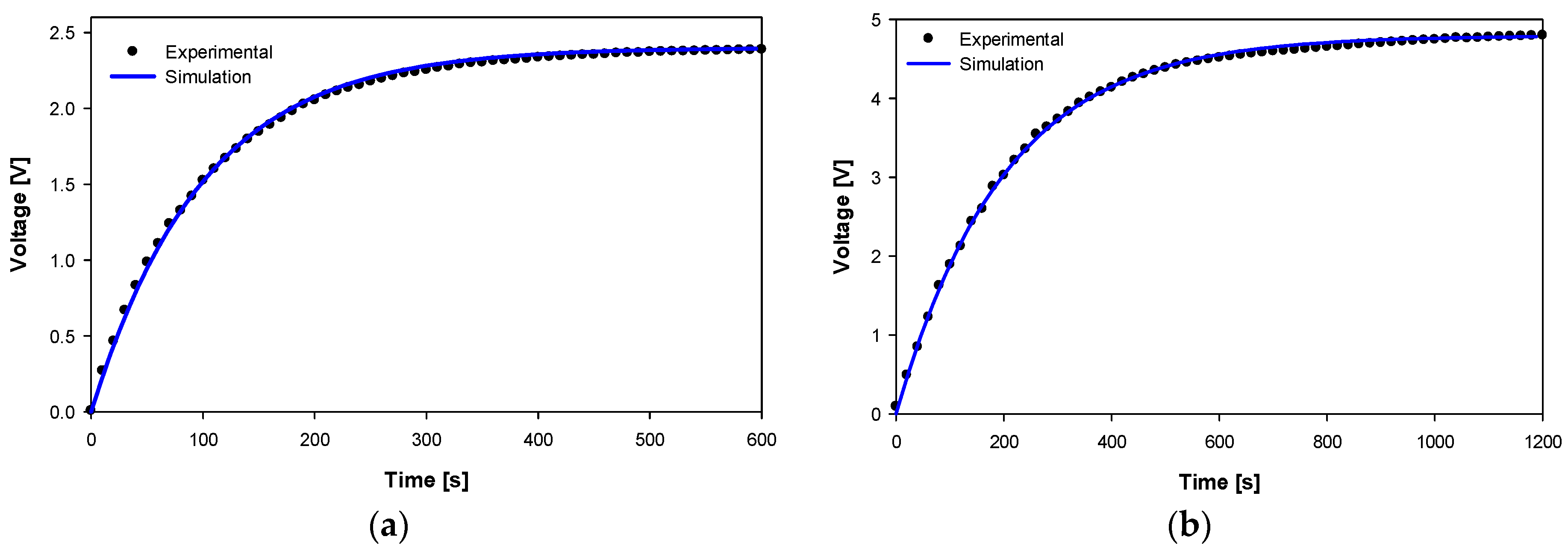
Next, the two-diode rectifier and a 1 mF storage capacitor were added to the circuit to supply the load resistor, as shown in Figure 2. Note that a tantalum capacitor was selected for its low leakage current, high capacitance, and long-term stability. The experimental results obtained with a 20 kV RMS power supply are shown in Figure 8. The simulations were performed in LTspice version 17.1.8 with the layout shown in Figure 2.
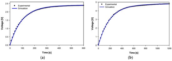
Figure 8.
Experimental results at 20 kV-RMS with two-diode rectifier, 1 mF capacitor and load resistor assuming C1 = 230 pF and C2 = 8.5 pF. (a) Rload = 100 kΩ. (b) Rload = 200 kΩ.
Figure 8 shows the great similarity between the experimental and simulated results, confirming the usefulness of the equivalent circuit shown in Figure 2.
The experimental and simulation results presented in this section show that the voltage across the load terminals is directly proportional to the source voltage and is almost independent of the values of C1 and Cstorage. However, for a given resistive load, the time required to charge the capacitor increases with the product τ = RL·Cstorage, where τ is the time constant.
4.3. Concluding Remarks
This section develops the concluding remarks, which can be summarized as follows:
- ▪
- The results presented in this paper clearly show that when applying EFEH strategies, a limited amount of energy and power can be harvested, so low-power or ultra-low-power (ULP) wireless sensor nodes are required.
- ▪
- The results presented in Section 4.1 and Section 4.2 clearly show that the supply voltage Vs largely determines the energy harvesting potential, so that EFEH for high-voltage applications results in higher harvested energies.
- ▪
- The output voltage Vout also increases linearly with the supply voltage in both low- and high-voltage systems.
- ▪
- In general, high-voltage systems are preferred for EFEH because the high voltage supply tends to produce higher capacitive currents. However, high-voltage systems require greater insulation distances, i.e., the distances between live parts and ground, which reduces capacitive coupling and therefore the value of C2. It has been shown that it is possible to harvest power from typical residential voltages of 230 V due to the higher capacitive coupling. Although the energy harvested in low-voltage applications is lower than in high-voltage applications, the increased capacitive coupling partially compensates for the voltage limitations of EFEH in low-voltage systems. Therefore, there is a trade-off between voltage level and capacitive coupling, the latter depending on the insulation distance, since as this distance increases, the value of C2 and the potential for energy harvesting decrease.
- ▪
- For low-voltage systems, the harvester capacitance C1 in the layout shown in Figure 1 has a large effect on the output voltage Vout because C1 and Vout are proportional. Therefore, longer harvesters increase the energy scavenged.
- ▪
- For high-voltage systems (see Figure 2), the value of C1 has almost no effect on the output voltage or the energy harvested. This means that the dimensions of the harvester have little effect on the energy harvested.
- ▪
- Since the performance of EFEH systems depends on the values of the stray capacitances, the results are not always fully repeatable because the parasitic capacitance can be affected by external factors such as the effects of nearby grounded objects or environmental variables such as humidity or temperature [27].
- ▪
- It has also been observed in both low- and high-voltage applications that the output voltage Vout increases almost linearly with the value of the load resistance RL. However, the load resistance depends on the power of the electronic circuit associated with the harvester, which is usually less than a few MΩ.
- ▪
- By adding a diode rectifier and a storage capacitor Cstorage, the DC output voltage is almost independent of the value of Cstorage.
- ▪
- The use of a two-diode rectifier is advantageous over a four-diode rectifier due to the reduced number of components and the results obtained, which are almost the same.
- ▪
- By increasing the value of Cstorage, more energy can be stored and used by the electronic circuit. However, for a given resistive load, the time required to charge the capacitor increases with the product τ = RL·Cstorage, where τ is the time constant, thus reducing the frequency of the communications. Therefore, the size of Cstorage must be accurately calculated to store enough energy for all sensing and communication cycles while maximizing the number of communication cycles per day.
- ▪
- The effective value of the load resistance RL depends on the power required by the rest of the circuit (sensor module, DC/DC converter, microprocessor, and communication module). In a real circuit, it changes cyclically with the load level of Cstorage and the phase of the communication cycle (advertising parameter initialization, advertising start, transmission, delay, and sleep), exhibiting a cyclic load profile.
- ▪
- The final power available to the load depends strongly on the efficiency of the control circuit, which is a key point for the commercialization of EFEH-based sensors.
5. Conclusions
This paper has quantified the physical limit of electric field energy harvesting intended for low and high voltage power lines from theoretical, simulation, and experimental points of view. It has considered the physical harvester itself, but not the electronic circuitry required to transfer the harvested energy to the load. Energy harvesting systems are key elements for the widespread use of wireless sensor nodes. It has been shown that although high-voltage systems make it easier to harvest energy from the electric field, the increased capacitive coupling partially compensates for the voltage limitations of low-voltage EFEH. It has also been shown that increased load resistance results in higher output voltages and increased harvested power. EFEH-based sensors must typically operate in an intermittent on-off pattern due to the low energy harvested, requiring a storage capacitor. Therefore, the size of the capacitor must be carefully selected in order to store enough energy for all the sensing and communication cycles while optimizing the communication rate. In addition, stray capacitance affects EFEH performance, so this effect must be taken into account in the design phase of EFEH-based systems. The results presented in this work are valuable for batteryless and wireless sensor nodes for low voltage and high voltage, ranging from a few hundred V to a few hundred kV.
Author Contributions
Conceptualization, J.-R.R.; methodology, J.-R.R. and R.A.; formal analysis, J.-R.R., R.A., Y.O.N. and M.M.-E.; investigation; J.-R.R., R.A. and Y.O.N.; writing—original draft preparation, J.-R.R.; writing—review and editing; J.-R.R. and M.M.-E.; funding acquisition, J.-R.R. and M.M.-E. All authors have read and agreed to the published version of the manuscript.
Funding
This research was funded by Ministerio de Ciencia e Innovación de España, grant number PID2020-114240RB-I00 and by the Generalitat de Catalunya, grant number 2017 SGR 967.
Data Availability Statement
The data presented in this study are available in the paper.
Conflicts of Interest
The authors declare no conflict of interest.
References
- Zhou, J.; Zhang, J.; Xu, C.; Fang, L.; Wang, Y.; Zhuang, Y.; Jia, T.; Huang, Y.; Han, C. On the improvement of electric field energy harvesting from domestic power lines. AEU-Int. J. Electron. Commun. 2022, 155, 154349. [Google Scholar] [CrossRef]
- Riba, J.-R.; Moreno-Eguilaz, M.; Bogarra, S. Energy Harvesting Methods for Transmission Lines: A Comprehensive Review. Appl. Sci. 2022, 12, 10699. [Google Scholar] [CrossRef]
- Roscoe, N.M.; Judd, M.D. Harvesting energy from magnetic fields to power condition monitoring sensors. IEEE Sens. J. 2013, 13, 2263–2270. [Google Scholar] [CrossRef]
- Hernández-Guiteras, J.; Riba, J.-R.; Romeral, L. Improved design of an extra-high-voltage expansion substation connector through magnetic field analysis. Simul. Model. Pract. Theory 2014, 43, 96–105. [Google Scholar] [CrossRef]
- Liu, Y.; Riba, J.R.; Moreno-Eguilaz, M.; Sanllehí, J. Application of Thermoelectric Generators for Low-Temperature-Gradient Energy Harvesting. Appl. Sci. 2023, 13, 2603. [Google Scholar] [CrossRef]
- Ahmed Abdulkadir, A.; Al-Turjman, F. Smart-grid and solar energy harvesting in the IoT era: An overview. Concurr. Comput. Pract. Exp. 2021, 33, e4896. [Google Scholar] [CrossRef]
- Prajwal, K.T.; Manickavasagam, K.; Suresh, R. A review on vibration energy harvesting technologies: Analysis and technologies. Eur. Phys. J. Spec. Top. 2022, 231, 1359–1371. [Google Scholar] [CrossRef]
- Muscat, A.; Bhattacharya, S.; Zhu, Y. Electromagnetic Vibrational Energy Harvesters: A Review. Sensors 2022, 22, 5555. [Google Scholar] [CrossRef]
- Yang, F.; Du, L.; Yu, H.; Huang, P. Magnetic and Electric Energy Harvesting Technologies in Power Grids: A Review. Sensors 2020, 20, 1496. [Google Scholar] [CrossRef]
- Cetinkaya, O.; Akan, O.B. Electric-Field Energy Harvesting in Wireless Networks. IEEE Wirel. Commun. 2017, 24, 34–41. [Google Scholar] [CrossRef]
- Moghe, R.; Yang, Y.; Lambert, F.; Divan, D. A scoping study of electric and magnetic field energy harvesting for wireless sensor networks in power system applications. In Proceedings of the 2009 IEEE Energy Conversion Congress and Exposition, San Jose, CA, USA, 20–24 September 2009; pp. 3550–3557. [Google Scholar] [CrossRef]
- Zangl, H.; Bretterklieber, T.; Brasseur, G. Energy harvesting for online condition monitoring of high voltage overhead power lines. In Proceedings of the 2008 IEEE Instrumentation and Measurement Technology Conference, Victoria, BC, Canada, 12–15 May 2008; pp. 1364–1369. [Google Scholar] [CrossRef]
- Kim, H.; Choi, D.; Gong, S.; Park, K. Stray electric field energy harvesting technology using MEMS switch from insulated AC power lines. Electron. Lett. 2014, 50, 1236–1238. [Google Scholar] [CrossRef]
- Chang, K.; Kang, S.; Park, K.; Shin, S.; Kim, H.S.; Kim, H. Electric Field Energy Harvesting Powered Wireless Sensors for Smart Grid. J. Electr. Eng. Technol. 2012, 7, 75–80. [Google Scholar] [CrossRef]
- Sabovic, A.; Delgado, C.; Subotic, D.; Jooris, B.; De Poorter, E.; Famaey, J. Energy-Aware Sensing on Battery-Less LoRaWAN Devices with Energy Harvesting. Electronics 2020, 9, 904. [Google Scholar] [CrossRef]
- Kadechkar, A.; Moreno-Eguilaz, M.; Riba, J.-R.; Capelli, F. Low-Cost Online Contact Resistance Measurement of Power Connectors to Ease Predictive Maintenance. IEEE Trans. Instrum. Meas. 2019, 68, 4825–4833. [Google Scholar] [CrossRef]
- Zhang, J.; Li, P.; Wen, Y.; Zhang, F.; Yang, C. A management circuit with upconversion oscillation technology for electric-field energy harvesting. IEEE Trans. Power Electron. 2016, 31, 5515–5523. [Google Scholar] [CrossRef]
- Kang, S.; Yang, S.; Kim, H. Non-intrusive voltage measurement of ac power lines for smart grid system based on electric field energy harvesting. Electron. Lett. 2017, 53, 181–183. [Google Scholar] [CrossRef]
- Zhao, X.; Keutel, T.; Baldauf, M.; Kanoun, O. Energy harvesting for overhead power line monitoring. In Proceedings of the International Multi-Conference on Systems, Signals & Devices, Chemnitz, Germany, 20–23 March 2012. [Google Scholar] [CrossRef]
- Rodriguez, J.C.C.; Holmes, D.G.; McGrath, B.P.; Teixeira, C. Energy Harvesting from Medium Voltage Electric Fields using pulsed flyback conversion. In Proceedings of the 2016 IEEE 8th International Power Electronics and Motion Control Conference (IPEMC-ECCE Asia), Hefei, China, 22–26 May 2016; pp. 3591–3598. [Google Scholar] [CrossRef]
- Gulati, M.; Parizi, F.S.S.; Whitmire, E.; Gupta, S.; Ram, S.S.S.; Singh, A.; Patel, S.N.N. CapHarvester: A Stick-on Capacitive Energy Harvester Using Stray Electric Field from AC Power Lines. Proc. ACM Interact. Mob. Wearable Ubiquitous Technol. 2018, 2, 1–20. [Google Scholar] [CrossRef]
- Khan, M.R.; Islam, M.A.; Rana, M.M.; Haque, T.; Joy, S.I.I. A Circuit Model for Energy Harvesting from Fringing Electric Fields for Mobile Wearable Device Applications. Energies 2021, 14, 7016. [Google Scholar] [CrossRef]
- Moser, M.J.; Bretterklieber, T.; Zangl, H.; Brasseur, G. Strong and weak electric field interfering: Capacitive icing detection and capacitive energy harvesting on a 220-kV high-voltage overhead power line. IEEE Trans. Ind. Electron. 2011, 58, 2597–2604. [Google Scholar] [CrossRef]
- Zhao, X.; Keutel, T.; Baldauf, M.; Kanoun, O. Energy harvesting for a wireless-monitoring system of overhead high-voltage power lines. IET Gener. Transm. Distrib. 2013, 7, 101–107. [Google Scholar] [CrossRef]
- Riba, J.-R.; Capelli, F. Analysis of capacitance to ground formulas for different high-voltage electrodes. Energies 2018, 11, 1090. [Google Scholar] [CrossRef]
- Liu, Y.; Riba, J.R.; Moreno-Eguilaz, M. Energy Balance of Wireless Sensor Nodes Based on Bluetooth Low Energy and Thermoelectric Energy Harvesting. Sensors 2023, 23, 1480. [Google Scholar] [CrossRef] [PubMed]
- Shruti, H. Designing a Capacitive Sensing System for a Specific Application; Cypress: London, UK, 2011; pp. 1–14. [Google Scholar]
Disclaimer/Publisher’s Note: The statements, opinions and data contained in all publications are solely those of the individual author(s) and contributor(s) and not of MDPI and/or the editor(s). MDPI and/or the editor(s) disclaim responsibility for any injury to people or property resulting from any ideas, methods, instructions or products referred to in the content. |
© 2023 by the authors. Licensee MDPI, Basel, Switzerland. This article is an open access article distributed under the terms and conditions of the Creative Commons Attribution (CC BY) license (https://creativecommons.org/licenses/by/4.0/).