
A Review of Tags Anti-Collision Identification Methods Used in RFID Technology

Abstract
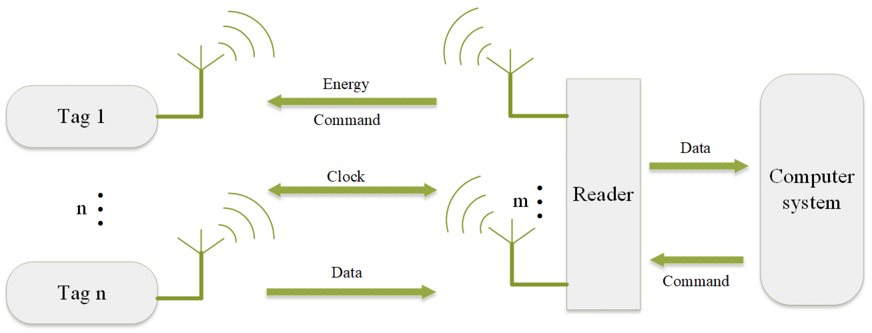
:1. Introduction
- Random reply: Passive RFID tags usually generate a random number through the internal pseudo-random number generator as the reply delay time. When the reader queries the tag, the tag uses this random number to determine the delay time and replies when the delay is over.
- Echo detection: The reader will send a specific signal when communicating with the tag, and then wait for a specified period of time to detect whether there is a tag reply. If the reader does not receive a reply within the specified time, it assumes that no tag is present at that location, thereby avoiding collisions.
- Anti-collision algorithm: When multiple tags are detected by the reader at the same time, the anti-collision algorithm can be used to avoid conflicts. This algorithm allows time-slicing of different tags, allowing them to reply or be acknowledged by readers at different intervals. By comparing the reader’s command with the tag’s identification code, the tags can be identified one by one, thereby avoiding conflicts.
1.1. Research Status at Home and Abroad
- (1)
- Anti-collision algorithm for tags based on TDMA
- (2)
- Anti-collision algorithm for tags based on BSS
- (3)
- Anti-collision algorithm for tags based on machine learning (ML)
1.2. Contribution of the Work in This Paper
- (1)
- An overview of the RFID tag anti-collision principle is presented.
- (2)
- Comparing the advantages and disadvantages of traditional anti-collision algorithms and introducing the advanced blind source separation anti-collision algorithm.
- (3)
- The application of machine learning in RFID tag anti-collision algorithm is summarized.
1.3. Organization of This Paper
2. TDMA-Based RFID Anti-Collision Algorithm
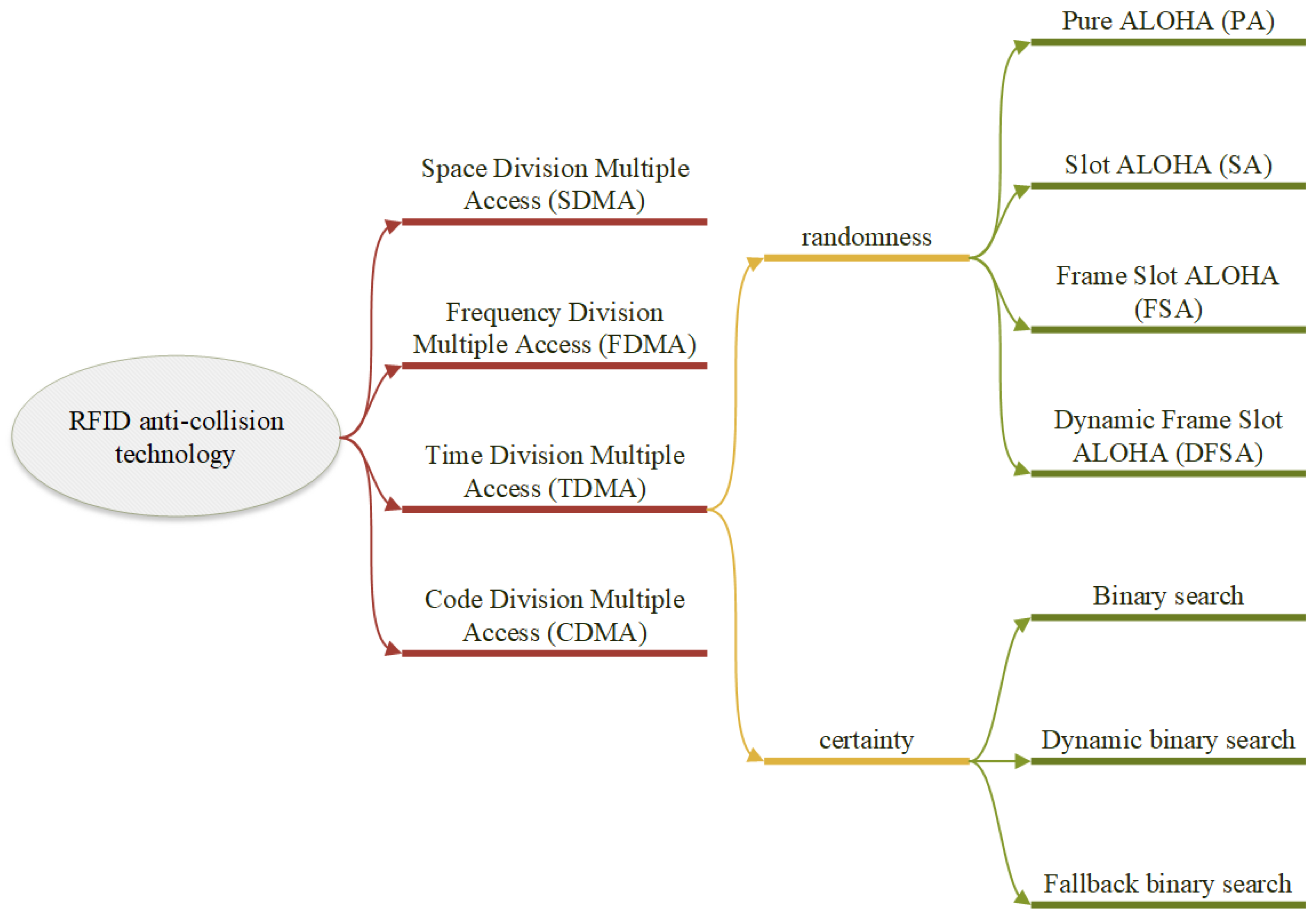
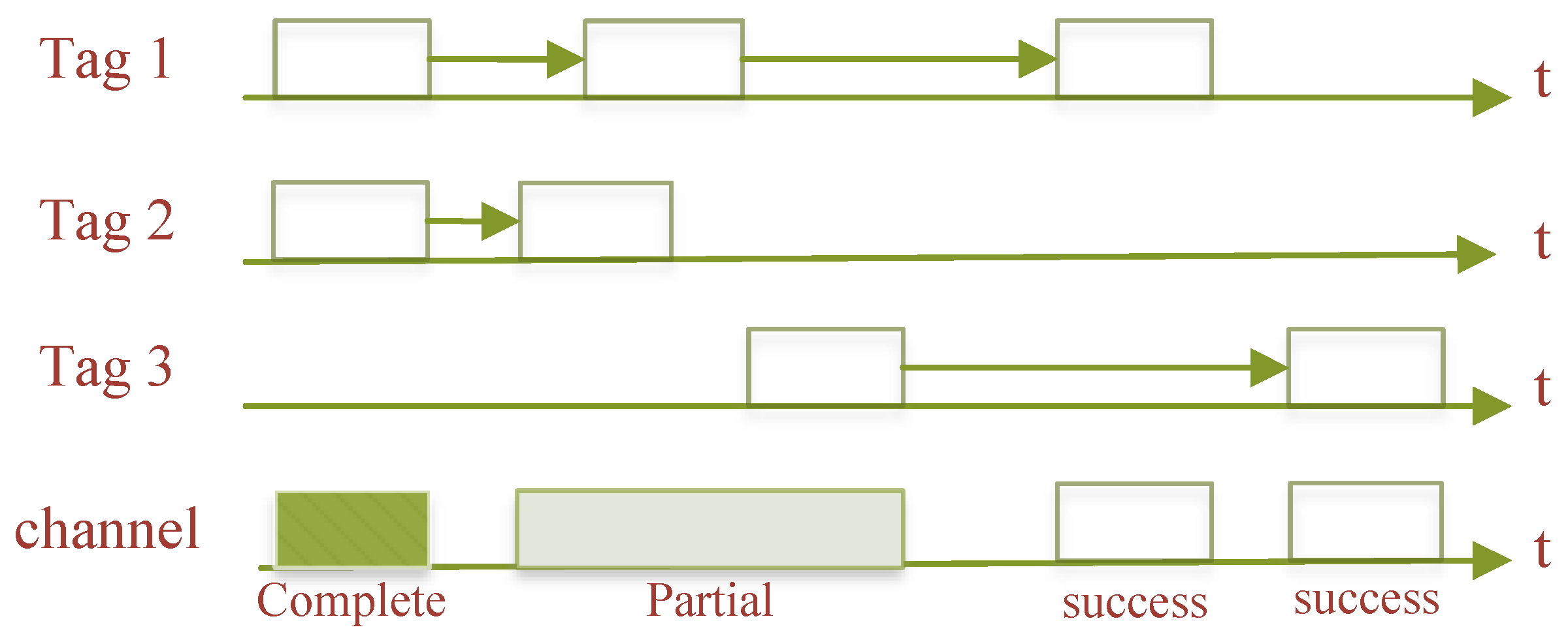
2.1. ALOHA-Based Anti-Collision Algorithm
- (1)
- Pure ALOHA algorithm
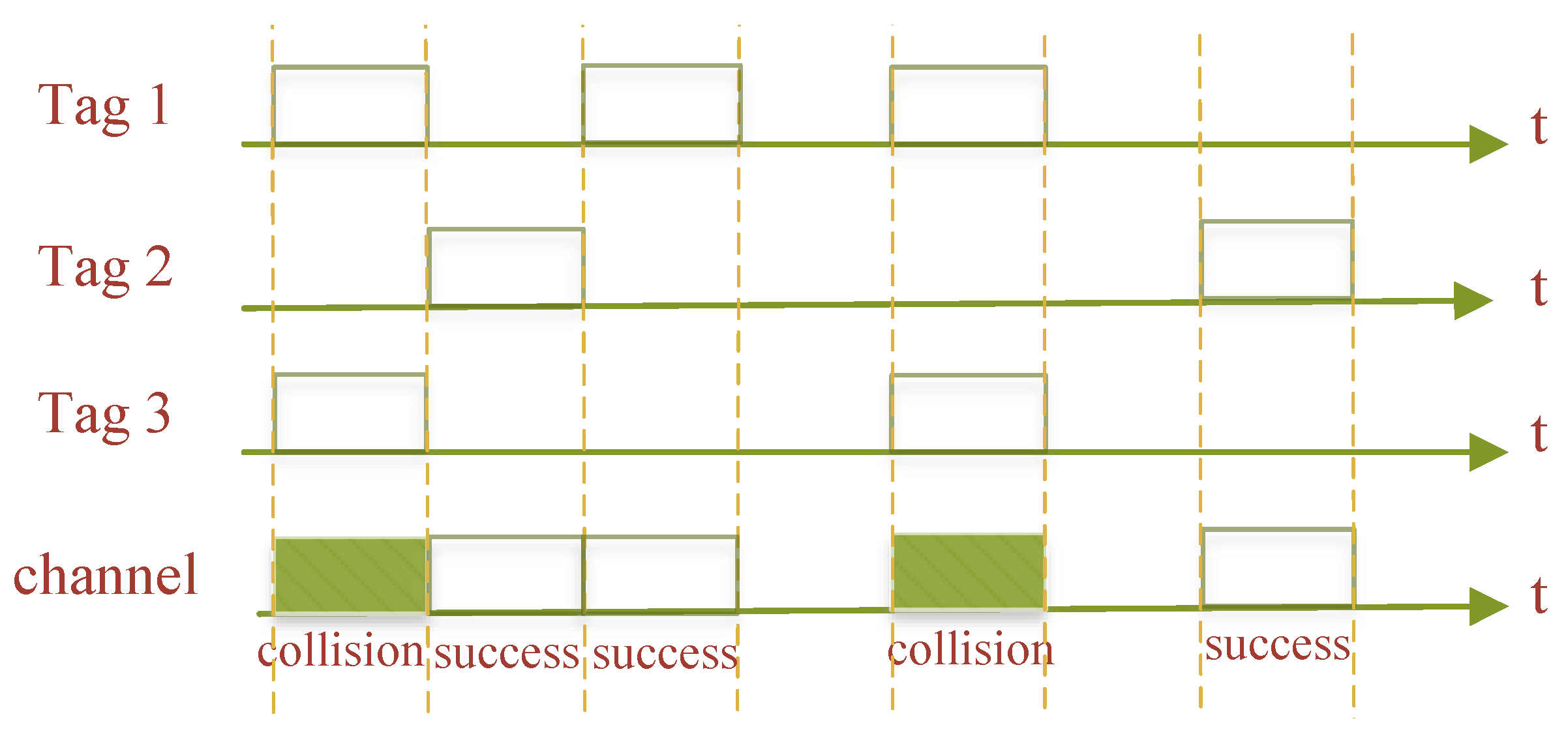
- (2)
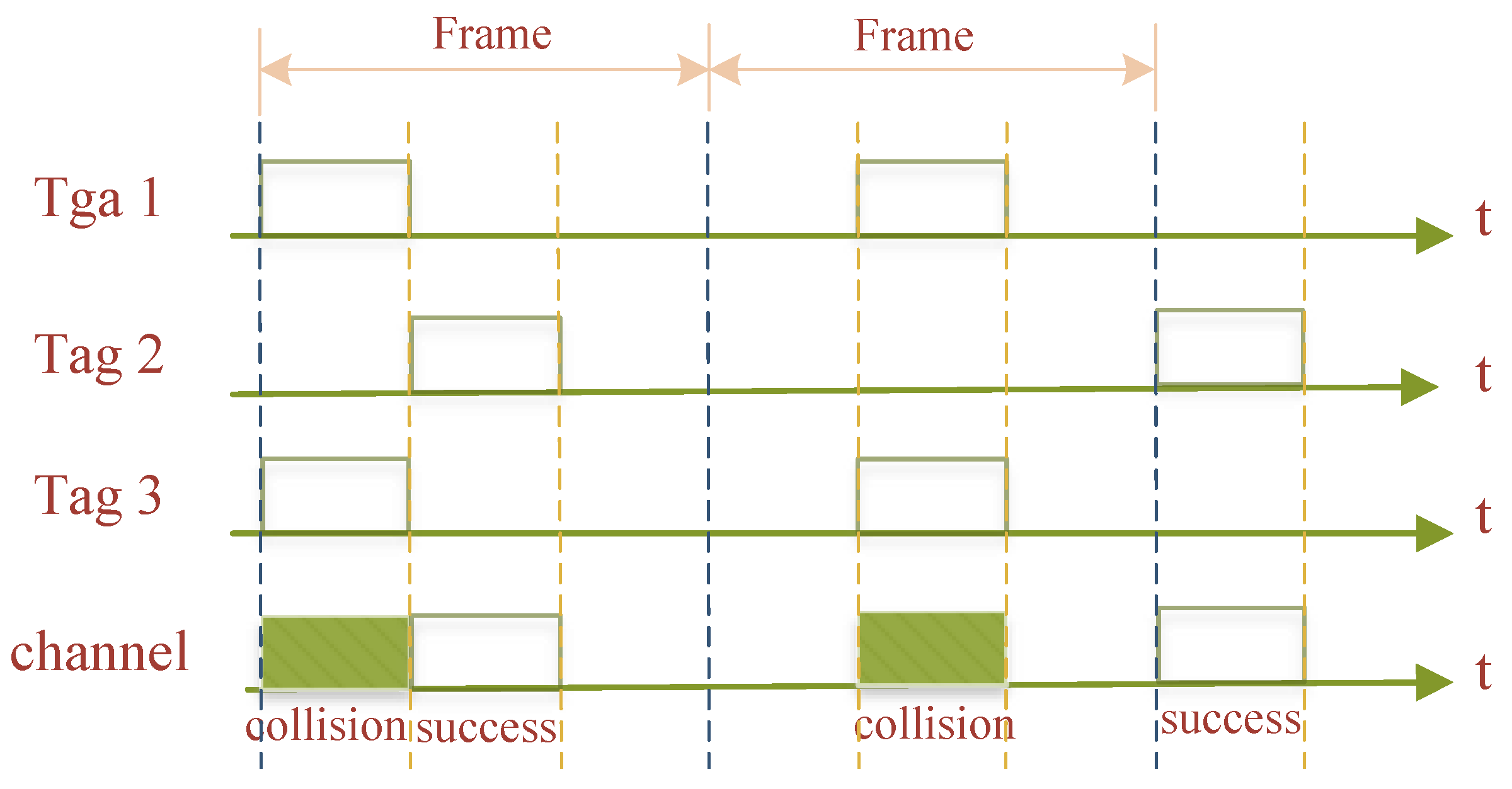
- Slotted ALOHA algorithm
- Successful slot: The RWD can successfully identify the tag supplied within this slot if just one tag transmits back information to the slot.
- Collision slot: If two or more tags transmit back information to the RWD within the slot, the information from the various tags will conflict and cause a tag collision, making it impossible for the RWD to recognize the tag within this slot.
- Idle slot: No tag is present in the slot to provide the RWD with return information.
- (3)
- Framed slotted ALOHA algorithm
- (4)
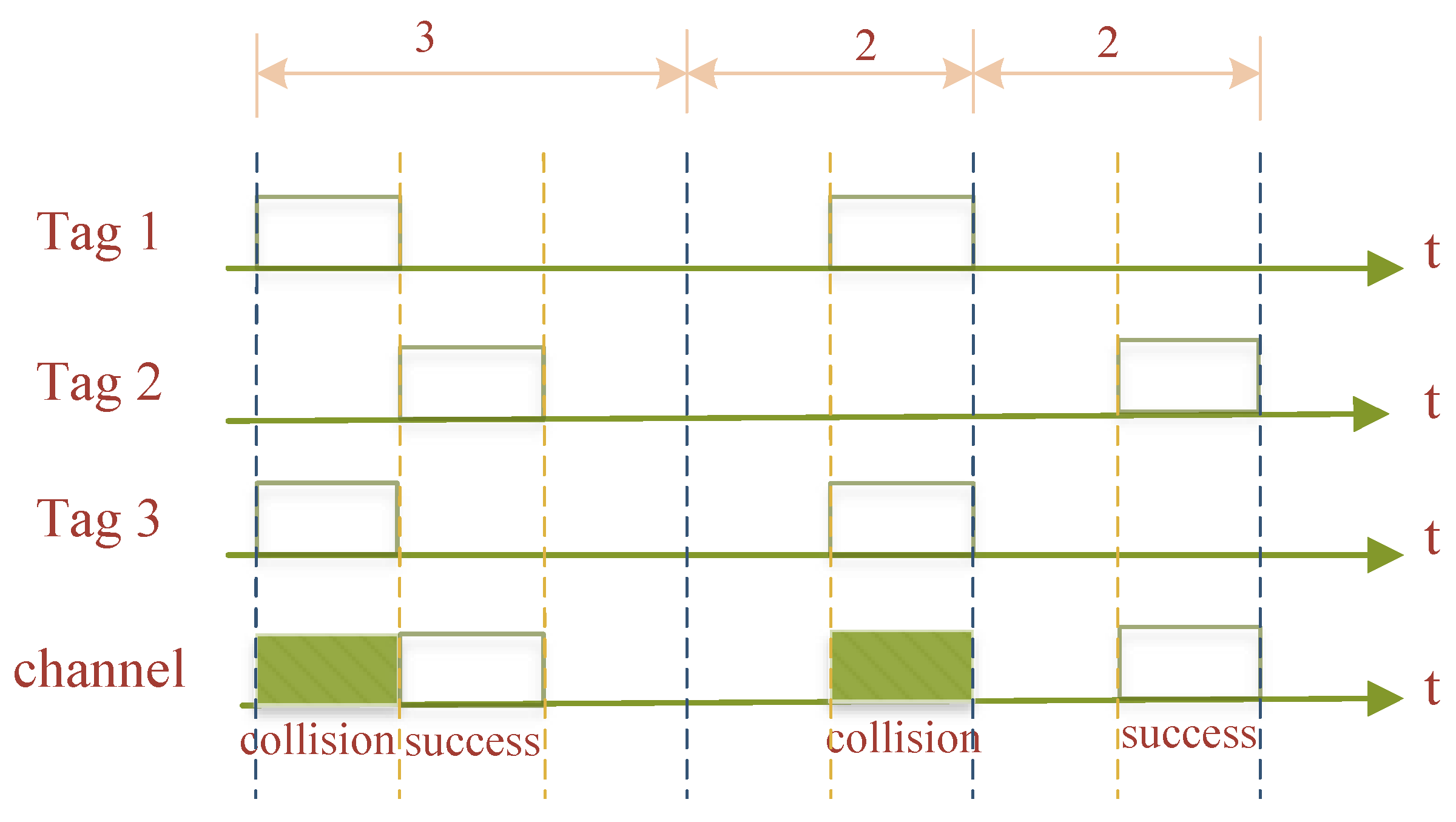
- Dynamic Framed Slotted ALOHA algorithm
2.2. Anti-Collision Algorithm Based on Tree Structure
- (1)
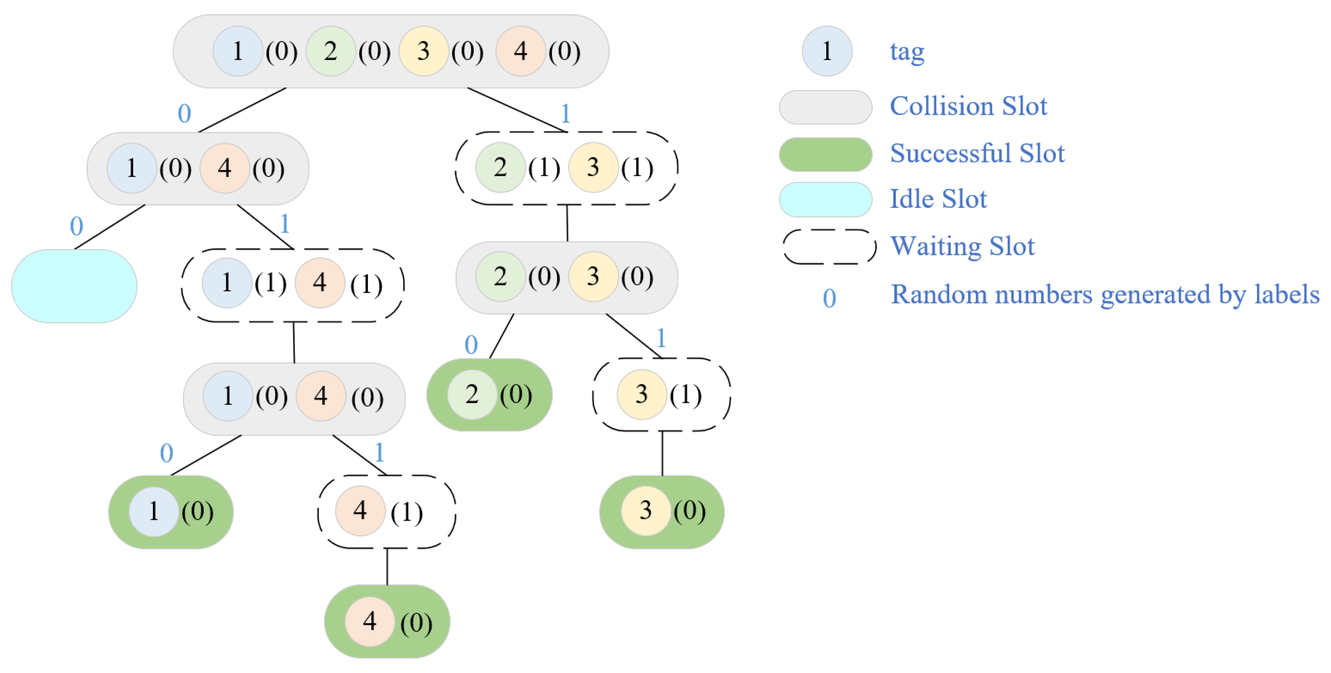
- Tree splitting algorithm
- (2)
- Binary search algorithm
- (1)
- When a tag enters the RWD’s valid recognition range, the RWD sends a maximum query sequence “Q” to all tags, starting at the same time the transmission of each tag’s individual sequence numbers to the RWD’s reception module.
- (2)
- The RWD compares the numbers on the same digit of the tag response serial number, and if there is a discrepancy, for example, some tag serial numbers have a “0” in that digit while others have a “1” in that digit, then it can be said that a tag collision has been formed.
- (3)
- After determining that a tag collision has occurred, the highest collision position of the query sequence “Q” is set to “0”, and the remaining low positions are all set to “1” to obtain a new query sequence “Q”. The number with the largest serial number is excluded one at a time until the RWD compares the number of the serial number of the tag response on the same number of digits is completely consistent, at which point no tag collision has occurred. The number with the least serial number is then chosen at this point.
- (4)
- The RWD picks the tag pair indicated by the least number of serial numbers, communicates with it, and then puts the tag into a “silent” condition so that it stops responding within the RWD’s recognition range. The tag can reply once more if it is moved both inside and outside of the RWD’s effective recognition range.
- (5)
- Process (a) is repeated and the tag with the second-to-last serial number is selected for data exchange.
- (6)
- This process is looped several times until all tags have been successfully identified.
- (3)
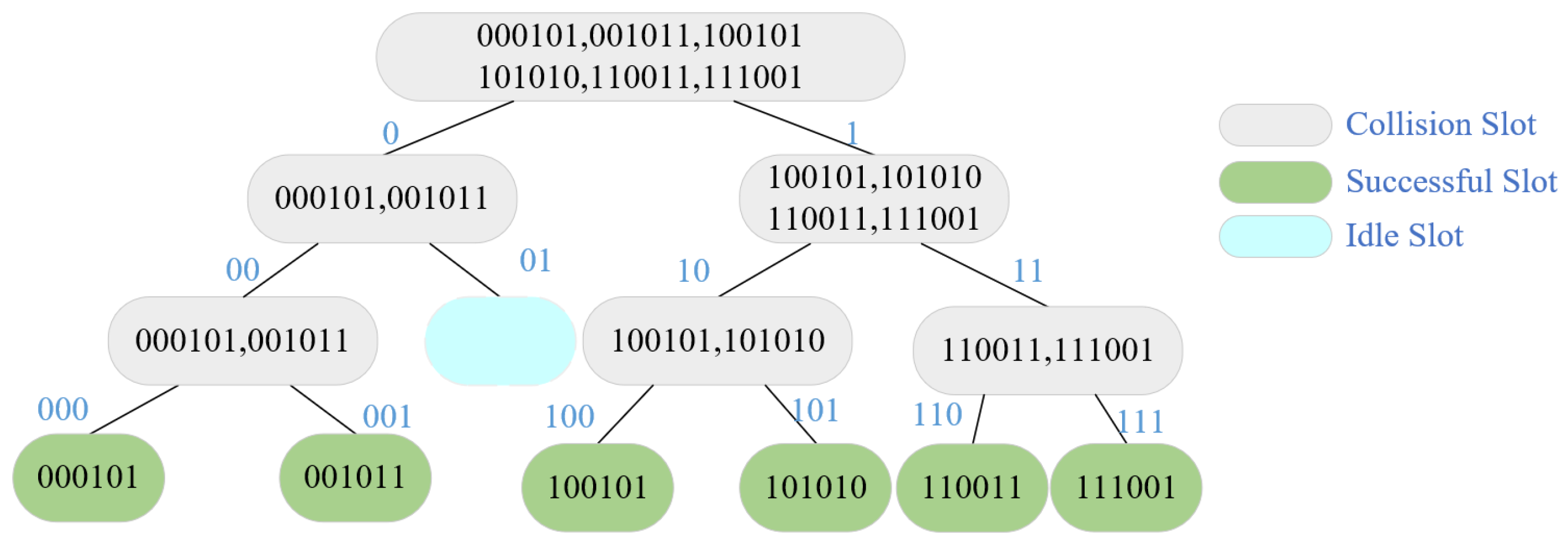
- Query tree algorithm
3. Hybrid Tag Anti-Collision Algorithm
3.1. ALOHA Algorithm Combined with Binary Trees
- (1)
- The RWD initializes to empty the queue stack and sends the request command (NULL).
- (2)
- All tags within range of the RWD will respond, not at the same time, but with response slots based on the first 3 bits of information. Tag 1 responds immediately. Tags 2, 3, and 4 respond after a one-slot delay. Tags 5 and 6 respond after a two-slot delay.
- (3)
- At compensation slot 0, there is only one tag, which the RWD identifies directly. At compensation slot 1, there are three tag responses, encoded by Manchester, decoded to obtain X0X1XXX10, and the RWD identifies the search string as 001 and 100 based on the first three pieces of information pressed into the search queue stack. At compensation slot 2, there are two tag responses, which are decoded to give 0111XXX10, and again, the search string is determined to be 011 based on the first three pieces of information, which are pressed into the search queue stack. At this point, the search strings in the stack are 001, 100, and 011.
- (4)
- The RWD sends the search request command (request 001), tags 2 and 3 respond, and at this time the tag sends the response bits for bits 4 to 9, where tag 2 responds at compensation slot 2 and tag 3 responds at compensation slot 3. If there is only one tag response at each of compensation slots 2 and 3, the RWD recognizes it directly.
- (5)
- The RWD sends the search request command (request 100), and tag 4 responds at compensation slot 1 for direct recognition.
- (6)
- The RWD sends the search request command (request 011), tags 5 and 6 respond at the compensation slot 2, the tag sends bits 4 to 9, which are encoded by Manchester and decoded to 1XXX10, and the RWD determines the new search string as 011101 and 011110 based on the first three bits of information obtained from the decoding and presses them into the search queue stack.
- (7)
- The RWD sends the search request command (request 011101), tag 5 responds at compensation slot 1, and the RWD recognizes it directly.
- (8)
- The RWD sends the search request command (request 011110), tag 6 responds at compensation slot 2, and the RWD recognizes it directly. At this point, all tags are recognized. End of story.
3.2. ALOHA Partitioning Ideas Combined with Tree-Based Algorithms
4. BSS-Based RFID Anti-Collision Algorithm
- Statistically independent and non-Gaussian;
- Insensitive to sign changes in the signal;
- The requirement of the algorithm for the uncertainty in the signal order is satisfied by the identification of the tag signal, which is independent of the order.
4.1. BSS Algorithm for Determined RFID Systems
- (1)
- Form the original data into an n-row, m-column matrix by columns.
- (2)
- Zero-mean each row of (representing a feature), i.e., subtract the mean of this row.
- (3)
- Pre-processing the data for whitening.
- (4)
- Set the value of the parameter learning rate .
- (5)
- Solve for at moment i, where initially can be assigned to a random matrix with a sum of one in each row.
- (6)
- The source signal at moment i will be solved based on the obtained in the previous step and formula .
- (7)
- Repeat steps (4) and (5) to solve the source signal at all times.
- (8)
- Combine the source signals obtained at each time to obtain the final result .
4.2. BSS Algorithm for Under-Determined RFID Systems
4.2.1. Combination of Tag Grouping and BSS Algorithms
4.2.2. NMF Algorithm for RFID Systems
- (1)
- The RWD simultaneously receives signals from synchronized tags and establishes a collision model for MIMO: Input source signal , mixed received signal , where means that the received signal is smaller than the dimension of the source signal, that is, it deals with the under-determination problem.
- (2)
- and are initialized as arbitrary non-negative matrices, where is the estimation of the mixed matrix and is the estimation of the source signal matrix .
- (3)
- The objective function iteration error is set to . At the same time, a determinant constraint is applied to , and a sparsity constraint and a minimum correlation constraint are applied to at the same time, that is, is taken.
- (4)
- Iterate according to the iteration rules, judge the error in the adjacent two iterations, if it is not greater than , turn to step (5); Otherwise, repeat step (4).
- (5)
- The operation is stopped to obtain the final matrices and , and the separated signal is the source signal.
5. ML-Based RFID Anti-Collision Algorithm
5.1. LSTM Deep Neural Network Model
5.2. LSTM-Optimized DFSA Algorithm
6. Conclusions
7. Future Prospect
- (1)
- Low system throughput
- (2)
- Excessive time delay and low channel utilization
- (3)
- Co-channel interference
Author Contributions
Funding
Data Availability Statement
Conflicts of Interest
References
- Li, H.; Wang, H.; Shang, Z.; Li, Q.; Xiao, W. Low-power UHF handheld RFID reader design and optimization1. In Proceedings of the 2010 8th World Congress on Intelligent Control and Automation, Jinan, China, 7–9 July 2010. [Google Scholar]
- Hussain, Z.; Sheng, Q.Z.; Zhang, W.E. A review and categorization of techniques on de-vice-free human activity recognition. J. Netw. Comput. Appl. 2020, 167, 102738. [Google Scholar] [CrossRef]
- Liu, D.; Zuo, L. Blind source separation anti-collision algorithm for MIMO type RFID with sensing tags. Sens. Microsyst. 2017, 36, 153–156. [Google Scholar]
- Li, H.; Wang, H.; Song, Z. ICA-based UHF RFID multi-tag hybrid data blind separation. In Fifth International Conference on Machine Vision (ICMV 2012): Algorithms, Pattern Recognition, and Basic Technologies; SPIE: Wuhan, China, 2013; Volume 8784. [Google Scholar]
- Schuster, E.W.; Allen, S.J.; Brock, D.L. Global RFID: The Value of the EPCglobal Network for Supply Chain Management; Springer Science & Business Media: Berlin/Heidelberg, Germany, 2007. [Google Scholar]
- Yu, S.-S.; Zhan, Y.; Wang, Y. RFID anti-collision algorithm based on bi-directional binary exponential index. In Proceedings of the 2007 IEEE International Conference on Automation and Logistics, Jinan, China, 18–21 August 2007. [Google Scholar]
- Djeddou, M.; Khelladi, R.; Benssalah, M. Improved RFID anti-collision algorithm. AEU-Int. J. Electron. Commun. 2013, 67, 256–262. [Google Scholar] [CrossRef]
- Jia, X.; Feng, Q.; Ma, C. An efficient anti-collision protocol for RFID tag identification. IEEE Commun. Lett. 2010, 14, 1014–1016. [Google Scholar] [CrossRef]
- Šolić, P.; Radić, J.; Rožić, N. Energy efficient tag estimation method for ALOHA-based RFID systems. IEEE Sens. J. 2014, 14, 3637–3647. [Google Scholar] [CrossRef]
- Bagnato, G.; Maselli, G.; Petrioli, C.; Vicari, C. Performance analysis of anti-collision protocols for RFID systems. In Proceedings of the VTC Spring 2009-IEEE 69th Vehicular Technology Conference, Barcelona, Spain, 26–29 April 2009. [Google Scholar]
- Zhihong, Q.; Xue, W. An overview of anti-collision protocols for radio frequency identi-fication devices. China Commun. 2014, 11, 44–59. [Google Scholar] [CrossRef]
- Liu, L.; Lai, S. ALOHA-based anti-collision algorithms used in RFID system. In Proceedings of the 2006 International Conference on Wireless Communications, Networking and Mobile Computing, Wuhan, China, 22–24 September 2006. [Google Scholar]
- Zhen, B.; Kobayashi, M.; Shimizu, M. Framed ALOHA for multiple RFID objects identi-fication. IEICE Trans. Commun. 2005, 88, 991–999. [Google Scholar] [CrossRef]
- Chen, W.-T.; Lin, G. An efficient anti-collision method for tag identification in a RFID system. IEICE Trans. Commun. 2006, 89, 3386–3392. [Google Scholar] [CrossRef]
- Umelo, N.H.; Noordin, N.K.; Rasid, M.F.A.; Tan, K.G.; Hashim, F. Efficient Tag Grouping RFID Anti-Collision Algorithm for Internet of Things Applications Based on Improved K-Means Clustering. IEEE Access 2023, 11, 11102–11117. [Google Scholar] [CrossRef]
- Su, J.; Chen, Y.; Sheng, Z.; Huang, Z.; Liu, A.X. From M-ary query to bit query: A new strategy for efficient large-scale RFID identification. IEEE Trans. Commun. 2020, 68, 2381–2393. [Google Scholar] [CrossRef]
- Zhang, L.; Zhang, J.; Tang, X. Assigned tree slotted aloha RFID tag anti-collision protocols. IEEE Trans. Wirel. Commun. 2013, 12, 5493–5505. [Google Scholar] [CrossRef]
- Namboodiri, V.; DeSilva, M.; Deegala, K.; Ramamoorthy, S. An extensive study of slotted Aloha-based RFID anti-collision pro-tocols. Comput. Commun. 2012, 35, 1955–1966. [Google Scholar] [CrossRef]
- Abbasian, A.; Safkhani, M. CNCAA: A new anti-collision algorithm using both collided and non-collided parts of information. Comput. Netw. 2020, 172, 107159. [Google Scholar] [CrossRef]
- Jiang, Z.; Li, B.; Yang, M.; Yan, Z. LC-DFSA: Low complexity dynamic frame slotted Aloha anti-collision algorithm for RFID system. Sensors 2019, 20, 228. [Google Scholar] [CrossRef] [PubMed]
- Wang, Z.; Yu, H.; Xu, X. Comparative Analysis of Anti-collision Algorithm Based on ALOHA Algorithm and Its Improvement Algorithm. In Proceedings of the 2022 IEEE 5th International Conference on Information Systems and Computer Aided Education (ICISCAE), Dalian, China, 23–25 September 2022. [Google Scholar]
- Abderrahmene, F.; Mustapha, B.; Abdenour, K. A New Rfid Anti-Collision Technique Based On Time-Hopping Sub Slots Early Estimation. In Proceedings of the 2023 International Conference on Advances in Electronics, Control and Communication Systems (ICAECCS), Blida, Algeria, 6–7 March 2023. [Google Scholar]
- Myung, J.; Lee, W.; Srivastava, J. Adaptive binary splitting for efficient RFID tag an-ti-collision. IEEE Commun. Lett. 2006, 10, 144–146. [Google Scholar] [CrossRef]
- Tripathi, S.; Jain, V.K. Performance analysis of adaptive tree-based anti-collision protocol using M-ary splitting in RFID. In Proceedings of the 2019 10th International Conference on Computing, Communication and Networking Technologies (ICCCNT), Kanpur, India, 6–8 July 2019. [Google Scholar]
- Cui, Y.; Zhao, Y. Performance evaluation of a multi-branch tree algorithm in RFID. IEEE Trans. Commun. 2010, 58, 1356–1364. [Google Scholar] [CrossRef]
- Law, C.; Lee, K.; Siu, K. Efficient memoryless protocol for tag identification. In Proceedings of the 4th International Workshop on Discrete Algorithms and Methods for Mobile Computing and Commu-Nications, Boston, MA, USA, 11 August 2000. [Google Scholar]
- Li, G.; Sun, H.; Li, Z.; Wu, P.; Inserra, D.; Su, J.; Fang, X.; Wen, G. A Dynamic Multi-ary Query Tree Protocol for Passive RFID Anti-collision. Comput. Mater. Contin. 2022, 72, 4931–4944. [Google Scholar] [CrossRef]
- Lai, Y.C.; Chen, S.Y.; Hailemariam, Z.L.; Lin, C.C. A bit-tracking knowledge-based query tree for RFID tag identification in IoT systems. Sensors 2022, 22, 3323. [Google Scholar] [CrossRef]
- Ai, Y.; Bai, T.; Xu, Y.; Zhang, W. Anti-collision algorithm based on slotted random regressive-style binary search tree in RFID technology. IET Commun. 2022, 16, 1200–1208. [Google Scholar] [CrossRef]
- Jia, X.; Feng, Q.; Yu, L. Stability analysis of an efficient anti-collision protocol for RFID tag identification. IEEE Trans. Commun. 2012, 60, 2285–2294. [Google Scholar] [CrossRef]
- Zhang, H.; Gao, L.; Luo, H.G.; Zhai, Y. Research on the RFID anticollision strategy based on decision tree. Wirel. Commun. Mob. Comput. 2022, 2022, 1–7. [Google Scholar] [CrossRef]
- Hu, H.; Wang, H. Improved CT Algorithm Based on Bit Transform. In Proceedings of the 2022 IEEE 14th International Conference on Advanced Infocomm Technology (ICAIT), Chongqing, China, 8–11 July 2022. [Google Scholar]
- Shin, J.; Jeon, B.; Yang, D. Multiple RFID tags identification with M-ary query tree scheme. IEEE Commun. Lett. 2013, 17, 604–607. [Google Scholar] [CrossRef]
- Yuan, L.; He, Y. Application of ICA-based anti-collision algorithm in RFID system. Analog. Integr. Circuits Signal Process. 2010, 63, 169–175. [Google Scholar] [CrossRef]
- Dacuña, J.; Melià-Seguí, J.; Pous, R. Multi-tag spatial multiplexing in UHF RFID systems. IEICE Electron. Express 2012, 9, 1701–1706. [Google Scholar] [CrossRef]
- Liu, D. Research on anti-collision algorithm of tag blind source separation based on MIMO RFID. Hefei Univ. Technol. 2017, 6, 66. [Google Scholar]
- Zhu, W.; Zhang, A. Improvements on Tags Anti-Collision Algorithm in RFID System. Eng. Lett. 2019, 27, 4. [Google Scholar]
- Yang, L. Research on efficient identification of tags by multi-antenna RFID system. Qingdao Univ. Sci. Technol. 2018, 10, 59. [Google Scholar]
- Leplat, V.; Ang, A.M.S.; Gillis, N. Minimum-volume rank-deficient nonnegative matrix factorizations. In Proceedings of the ICASSP 2019—2019 IEEE International Conference on Acoustics, Speech and Signal Processing (ICASSP), Brighton, UK, 12–17 May 2019. [Google Scholar]
- Zhang, Y.; Fang, Y. A NMF algorithm for blind separation of uncorrelated signals. In Proceedings of the 2007 International Conference on Wavelet Analysis and Pattern Recognition, Beijing, China, 2–4 November 2007; Volume 3. [Google Scholar]
- Waldrop, J.; Engels, D.W.; Sarma, S.E. Colorwave: An anticollision algorithm for the reader collision problem. In Proceedings of the IEEE International Conference on Communications, ICC’03, Anchorage, AK, USA, 11–15 May 2003; Volume 2. [Google Scholar]
- Jing, C.; Luo, Z.; Chen, Y.; Xiong, X. Blind anti-collision methods for RFID system: A comparative analysis. Infocommun. J. 2020, 12, 8–16. [Google Scholar] [CrossRef]
- Alotaibi, M.; Murad, M.; Alhuthali, S.A.; Al-Osaimi, F.R.; Aldosari, F. MIMO Radio Frequency Identification: A Brief Survey. Sensors 2022, 22, 4115. [Google Scholar] [CrossRef]
- Xiong, J.; Huang, Z.; Xie, S.; Ye, G.; Wang, Y.; Lu, R. A Simple Scheme for 2FSK Signal Extraction Based on Independent Component Analysis with Cosine Pulse Reference Signal. In Proceedings of the 2022 IEEE/CIC International Conference on Communications in China (ICCC), Foshan, China, 11–13 August 2022; pp. 355–359. [Google Scholar]
- Arjona, L.; Landaluce, H.; Perallos, A.; Onieva, E. Scalable RFID tag estimator with enhanced accuracy and low estimation time. IEEE Signal Process. Lett. 2017, 24, 982–986. [Google Scholar] [CrossRef]
- Vales-Alonso, J.; Bueno-Delgado, V.; Egea-Lopez, E.; Gonzalez-Castano, F.J.; Alcaraz, J. Multiframe maximum-likelihood tag estimation for RFID anticol-lision protocols. IEEE Trans. Ind. Inform. 2011, 7, 487–496. [Google Scholar] [CrossRef]
- Wang, S.; Aggarwal, C.; Liu, H. Using a random forest to inspire a neural network and improving on it. In Proceedings of the 2017 SIAM International Conference on Data Mining; Society for Industrial and Applied Mathematics: Houston, TX, USA, April 2017. [Google Scholar]
- Filho, I.E.d.B.; Silva, I.; Viegas, C.M.D. An effective extension of anti-collision protocol for RFID in the industrial Internet of Things (IIoT). Sensors 2018, 18, 4426. [Google Scholar] [CrossRef]
- Charbuty, B.; Abdulazeez, A. Classification based on decision tree algorithm for machine learning. J. Appl. Sci. Technol. Trends 2021, 2, 20–28. [Google Scholar] [CrossRef]
- Zhang, Z. Introduction to machine learning: K-nearest neighbors. Ann. Transl. Med. 2016, 4, 218. [Google Scholar] [CrossRef]
- Steinwart, I.; Christmann, A. Support Vector Machines; Springer Science & Business Media: Berlin/Heidelberg, Germany, 2008. [Google Scholar]
- Cervantes, J.; Garcia-Lamont, F.; Rodríguez-Mazahua, L.; Lopez, A. A comprehensive survey on support vector machine classification: Applications, challenges and trends. Neurocomputing 2020, 408, 189–215. [Google Scholar] [CrossRef]
- Sekulić, A.; Kilibarda, M.; Heuvelink, G.B.; Nikolić, M.; Bajat, B. Random forest spatial interpolation. Remote Sens. 2020, 12, 1687. [Google Scholar] [CrossRef]
- Chen, S.; Webb, G.I.; Liu, L.; Ma, X. A novel selective naïve Bayes algorithm. Knowl.-Based Syst. 2020, 192, 105361. [Google Scholar] [CrossRef]
- Fan, F.L.; Xiong, J.; Li, M.; Wang, G. On interpretability of artificial neural networks: A survey. IEEE Trans. Radiat. Plasma Med. Sci. 2021, 5, 741–760. [Google Scholar] [CrossRef] [PubMed]
- Abramson, N. Multiple access in wireless digital networks. Proc. IEEE 1994, 82, 1360–1370. [Google Scholar] [CrossRef]
- Hu, J.; Li, Q.; Min, H. Application of time slot ALOHA method in anti-collision problem of RFID system. J. Appl. Sci. 2005, 5, 489–492. [Google Scholar]
- Vogt, H. Multiple object identification with passive RFID tags. In Proceedings of the IEEE International Conference on Systems, Man and Cybernetics, Yasmine Hammamet, Tunisia, 6–9 October 2002; Volume 3. [Google Scholar]
- Xia, H.; Tang, M.; Jin, H. A time slot ALOHA-based anti-collision algorithm for RFID systems. Microcomput. Inf. 2008, 17, 239–241. [Google Scholar]
- Prodanoff, Z.G. Optimal frame size analysis for framed slotted ALOHA based RFID net-works. Comput. Commun. 2010, 33, 648–653. [Google Scholar] [CrossRef]
- Tong, Q.; Zhang, Q.; Min, R.; Zou, X. Bayesian estimation in dynamic framed slotted ALOHA algorithm for RFID system. Comput. Math. Appl. 2012, 64, 1179–1186. [Google Scholar] [CrossRef]
- Xu, L.; Lan, Y. Implementation of RFID binary search method for collision prevention. Appl. Microcontroll. Embed. Syst. 2006, 5, 33–35. [Google Scholar]
- Massey, J.L. Collision-resolution algorithms and random-access communications. In Multi-User Communication Systems; Springer: New York, NY, USA, 1981; Volume 265, pp. 73–137. [Google Scholar]
- Sheng, Y.; Du, X. Improved Design and Implementation of Dynamic Binary Search An-ti-collision Algorithm. Comput. Sci. 2012, 39, 135–138. [Google Scholar]
- Han, X.; Nan, J. RFID anti-collision algorithm based on backward indexed binary tree search. Microelectronics 2013, 5, 708–712. [Google Scholar]
- An, J.; Wu, J.; Huang, S. Improved RFID binary search anti-collision algorithm. Comput. Eng. Appl. 2009, 45, 229–235. [Google Scholar]
- Yu, S.; Zhan, Y.; Wang, Z.; Tang, Z. Jumping dynamic tree anti-collision algorithm and its analysis. Comput. Eng. 2005, 09, 19–20+26. [Google Scholar]
- Li, F.; Cao, D.; Fu, M. Improvement of a BIBD encoded RFID anti-collision algorithm. Comput. Appl. Softw. 2012, 29, 151–154+166. [Google Scholar]
- Ryu, J.; Lee, H.; Seok, Y.; Kwon, T.; Choi, Y. A hybrid query tree protocol for tag collision arbitration in RFID systems. In Proceedings of the 2007 IEEE International Conference on Communications, Glasgow, UK, 24–28 June 2007. [Google Scholar]
- Sun, W.; Jin, C. New RFID dynamic frame time slot ALOHA anti-collision algorithm. Inf. Control 2012, 41, 233–237. [Google Scholar]
- Xu, P. Research on RFID tag anti-collision algorithm. Inn. Mong. Univ. 2020, 1, 64. [Google Scholar]
- Qian, D. Research on hybrid anti-collision algorithm based on tag identification code grouping. Hebei Univ. Technol. 2014, 7, 69. [Google Scholar]
- Cao, J.; Dou, C. An improved hybrid query tree anti-collision algorithm. Small Microcomput. Syst. 2015, 36, 322–326. [Google Scholar]
- Wang, G.; Zhao, L.; Dong, Z. Research on RFID hybrid collision algorithm. J. Eng. Heilongjiang Univ. 2012, 3, 80–84. [Google Scholar]
- Zhang, J.; He, Y.; Chen, H.; Liu, M. Hybrid anti-collision algorithm based on RFID system. In Electric, Electronic and Control Engineering; CRC Press: Boca Raton, FL, USA, 2015; pp. 341–346. [Google Scholar]
- Qian, C. Research on Hybrid Anti Collision Algorithms for RFID Systems. Shanghai Jiao Tong Univ. 2018, 1, 66. [Google Scholar]
- Zhang, X.; Zhou, W. Research on binary tree RFID anti-collision algorithm for dynamic frame time slots. J. Syst. Simul. 2018, 30, 1063–1073. [Google Scholar]
- Wu, F. Analysis and Research on UHF RFID Label Anti-collision Analysis of algorithms. Nanjing Univ. Posts Telecommun. 2019, 2, 80. [Google Scholar]
- Wang, X.; Zhang, M.; Lu, Z. A Frame Breaking Based Hybrid Algorithm for UHF RFID Anti-Collision. Comput. Mater. Contin. 2019, 59, 873–883. [Google Scholar] [CrossRef]
- Zhou, W.; Jiang, N.; Wan, X. Hybrid RFID anti-collision algorithm based on ALOHA and multi branch tree. J. East China Univ. Technol. (Nat. Sci. Ed.) 2021, 44, 96–100. [Google Scholar]
- Mu, Y.; Ni, R.; Sun, Y.; Zhang, T.; Li, J.; Hu, T.; Tyas, T.L. A novel hybrid tag identification protocol for large-scale rfid systems. Comput. Mater. Contin. 2021, 68, 2516–2526. [Google Scholar] [CrossRef]
- Deville, Y.; Damour, J.; Charkani, N. Multi-tag radio-frequency identification systems based on new blind source separation neural networks. Neurocomputing 2002, 49, 369–388. [Google Scholar] [CrossRef]
- Yu, X.; Hu, D.; Xu, J. Blind Source Separation: Theory and Applications; John Wiley & Sons: Hoboken, NJ, USA, 2013. [Google Scholar]
- Li, H.; Jia, Z.; Wang, H.; Liu, J. UHF RFID Anti-collision Algorithm Based on Dynamic Slot Packet Blind Separation. J. Commun. 2012, 33, 47–53. [Google Scholar]
- Kim, C.S.; Park, K.L.; Kim, H.; Kim, S.D. An Efficient Stochastic Anti-Collision Algorithm Using Bit-Slot Mech-anism. In Proceedings of the International Conference on Parallel and Distributed Processing Techniques and Applications, PDPTA’04, Las Vegas, NV, USA, 21–24 June 2004. [Google Scholar]
- Yan, J. Research on Blind Source Separation Algorithm for RFID Tag Collision Prevention. Guangdong Univ. Technol. 2014, 10, 72. [Google Scholar]
- Mu, Y. Research and Performance Analysis of a Novel RFID Tag Collision Prevention Algorithm. Jiangxi Univ. Sci. Technol. 2015, 2, 68. [Google Scholar]
- Pu, L.; Wu, H.C.; Yan, K.; Gao, Z.; Wang, X.; Xiang, W. Novel three-hierarchy multiple-tag-recognition technique for next generation RFID systems. IEEE Trans. Wirel. Commun. 2019, 19, 1237–1249. [Google Scholar] [CrossRef]
- Wang, Y.-X.; Zhang, Y.-J. Nonnegative matrix factorization: A comprehensive review. IEEE Trans. Knowl. Data Eng. 2012, 25, 1336–1353. [Google Scholar] [CrossRef]
- Yue, K.; Sun, L.; You, B.; Lou, L. Parallel recognition and anti-collision algorithm based on underdetermined blind separation. J. Zhejiang Univ. (Eng. Sci. Ed.) 2014, 48, 865–870. [Google Scholar]
- Zhang, X.; Jin, Y. Research of under-determined blind source separation anti-collision algorithm based on RFID frame-slot. J. Syst. Simul. 2016, 28, 1100. [Google Scholar]
- Zhang, X.; Wang, Q.; Jin, Y. Under-Determined Blind Source Separation Anti-collision Algorithm for RFID Based on Adaptive Tree Grouping. In Artificial Intelligence and Security: 5th International Conference, ICAIS 2019, New York, NY, USA, 26–28 July 2019; Springer International Publishing: Cham, Switzerland, 2019. [Google Scholar]
- Jin, Y.; Zhang, X.; Wang, Q. An Anti-Collision Algorithm for Hamming Regrouping Based on Underdetermined Blind Separation of RFID Systems. J. Syst. Simul. 2017, 29, 1514–1520. [Google Scholar]
- Luo, Z.; Jing, C.; Chen, Y.; Xiong, X. A new underdetermined NMF based anti-collision algorithm for RFID sys-tems. ISA Trans. 2022, 123, 472–481. [Google Scholar] [CrossRef]
- Chen, W.-T. An accurate tag estimate method for improving the performance of an RFID anticollision algorithm based on dynamic frame length ALOHA. IEEE Trans. Autom. Sci. Eng. 2008, 6, 9–15. [Google Scholar] [CrossRef]
- Hou, P.; Wang, Z.; Yan, C. Improvement of anti-collision algorithm based on RFID tags. Comput. Sci. 2019, 46, 359–362. [Google Scholar]
- Memon, M.Q.; He, J.; Yasir, M.A.; Memon, A. Improving efficiency of passive RFID tag anti-collision protocol using dynamic frame adjustment and optimal splitting. Sensors 2018, 18, 1185. [Google Scholar] [CrossRef]
- Wu, H.; Zeng, Y. Anti-collision protocol for RFID tags based on adaptive frame Aloha. Comput. Res. Dev. 2011, 48, 802–810. [Google Scholar]
- Yuan, L.; Du, Y.; He, Y.; Lv, M.; Cheng, Z. Parallel identifiable packet dynamic frame time slot ALOHA tag an-ti-collision algorithm. J. Electron. Inf. Technol. 2018, 40, 944–950. [Google Scholar]
- Yang, C.; Zhao, Y.; Li, B.; Chen, C.; Ding, H. Research on Anti-collision Algorithm of RFID Tags Based on Deep Learning. Mod. Electron. Technol. 2021, 44, 21–25. [Google Scholar]
- Xiang, S.; Qin, Y.; Zhu, C.; Wang, Y.; Chen, H. LSTM networks based on attention ordered neurons for gear remaining life prediction. ISA Trans. 2020, 106, 343–354. [Google Scholar] [CrossRef]
- Deng, L.; Wu, Q.; Yang, S. PM2.5 Hourly Concentration Prediction Using SSAE Deep Feature Learning and LSTM Network. J. Environ. Sci. 2020, 40, 3422–3434. [Google Scholar]
- Want, R. RFID Explained: A Primer on Radio Frequency Identification Technologies; Springer Nature: Berlin/Heidelberg, Germany, 2022. [Google Scholar]
- Umelo, N.H.; Noordin, N.K.; Rasid, M.F.A.; Geok, T.K.; Hashim, F. Grouping based radio frequency identification anti-collision protocols for dense internet of things application. Int. J. Electr. Comput. Eng. 2022, 12, 5848. [Google Scholar] [CrossRef]
- Baghdad, A. An improved RFID anti-collision protocol (IMRAP) with low energy con-sumption and high throughput. Sci. Afr. 2022, 16, E01209. [Google Scholar]
- Fagbohunmi, G.S.; Chinenye, E.U. An Anti-collision Algorithms for Optimum Throughput in Passive RFID Identification System. Int. J. Latest Technol. Eng. Manag. Appl. Sci. 2022, XI, 35–41. [Google Scholar]
- Golsorkhtabaramiri, M.; Tahmasbi, M.; Ansari, S. A distributed mobile reader collision avoidance protocol for dense RFID networks. Wirel. Pers. Commun. 2022, 125, 2719–2735. [Google Scholar] [CrossRef]
- Pandian, M.T.; Chouhan, K.; Kumar, B.M.; Dash, J.K.; Jhanjhi, N.Z.; Ibrahim, A.O.; Abulfaraj, A.W. Improving efficiency of large rfid networks using a clustered method: A comparative analysis. Electronics 2022, 11, 2968. [Google Scholar] [CrossRef]
- Bai, M.; Yang, Z. Research and optimization of RFID tag anti-collision algorithm. In Proceedings of the International Conference on Electronic Information Engineering and Data Processing (EIEDP 2023), Nanchang, China, 17–19 March 2023; SPIE: Nanchang, China, 2023; Volume 12700. [Google Scholar]
- Shi, G.; Shen, X.; Gu, L.; Weng, S.; He, Y. Multipath Interference Analysis for Low-power RFID-Sensor under metal medium environment. IEEE Sens. J. 2023. [Google Scholar] [CrossRef]
- Jiang, M. Data Collection in Two-Tier IoT Networks with Radio Frequency (RF) Energy Harvesting Devices and Tags. Ph.D. Thesis, University of Wollongong, Wollongong, NSW, Australia, 2023. [Google Scholar]
- Salahdine, F.; Han, T.; Zhang, N. 5G, 6G, Beyond: Recent advances and future challenges. Ann. Telecommun. 2023, 1–25. [Google Scholar] [CrossRef]
- Majumdar, P.; Bhattacharya, D.; Mitra, S.; Bhushan, B. Application of Green IoT in Agriculture 4.0 and Beyond: Require-ments, Challenges and Research Trends in the Era of 5G, LPWANs and Internet of UAV Things. Wirel. Pers. Commun. 2023, 131, 1767–1816. [Google Scholar] [CrossRef]


| PA [10,18,19] | SA [11,12] | FSA [13,20] | DFSA [14,21,22] | |
|---|---|---|---|---|
| Tag requirements | Timer | Random number generators, timers, synchronization circuits | ||
| Advantages | Tags can transmit information at any time. | Eliminates some collision issues. | Reduces duplicate conflicts. | Effectively saves time slots. |
| Disadvantages | High probability of collision and partial collision problems. | Repeated conflicts are serious. | Prone to a large number of idle or conflicting slots. | The requirements for readers are relatively high. |
| Efficiency | 18.4% | 36.8% | 36.8% | 42.6% |
| Complexity | ||||
| QT [25,26,27] | BS [29,31,32] | TS [23,24] | |
|---|---|---|---|
| Tag requirements | Prefix matching and synchronization circuits | Have a unique binary identifier and be of equal length | Random number generators, synchronous circuits, counters that store static information |
| Advantages | Quick and efficient | Effectively avoid read and write conflicts | It is suitable for large-scale tag anti-collision environment |
| Disadvantages | Not suitable for large number of tags | Prone to performance bottlenecks | The adaptability to dynamic changes in tags is weak |
| ML Classifier | Advantages | Limitations |
|---|---|---|
| DT [49] | Solves multi-class and binary problems; fast; can handle missing values; easily interpretable | Prone to overfitting; sensitive to outliers |
| k-NN [50] | Solves multi-class and binary problems; easy to implement | Sensitive to noisy attributes; poor interpretability; slow to evaluate large training sets |
| SMV [51,52] | Solves binary problems; high accuracy; durable to noise; excellent in modeling nonlinear relations | Training is slow; high complexity and memory requirements |
| RF [53] | Solves multi-class and binary problems; higher accuracy compared to other models; robust to noise | Can be slow for real-time predictions; not very interpretable |
| Naive Bayes [54] | Solves multi-class and binary problems; simple to implement; fast | Ignores underlying geometry of data; requires predictors to be independent |
| ANN [55] | Solves multi-class and binary problems; handles noisy data; detects nonlinear relations between data; fast | Prone to overfitting on small datasets; computationally intensive |
| Applicable Frequency Bands | Anti-Collision Algorithms | International Standard of RFID | Throughput | Complexity |
|---|---|---|---|---|
| HF | QT/PA/FSA | ISO/IEC 18000-3 Mode 1 | Low | Low |
| DBSA | ISO 14443-3A | High | High | |
| SA | ISO/IEC 18000-3 Mode 2 | Low | Low | |
| DFSA | ISO 14443-3B | High | Medium | |
| UHF | TS | ISO/IEC 18000-6B EPCglobal Class 0 EPCglobal Class 1 | High | High |
| Q/FSA/DFSA | ISO/IEC 18000-6C EPCglobal C1G2 | High | Medium | |
| BFSA-muting-early-end | ISO/IEC 18000-6A | Medium | High |
| Number of Queries | First Query | Second Query | Third Query |
|---|---|---|---|
| Query sequence | 11111111 | 10111111 | 10101111 |
| Tag A | 10110010 | 10110010 | — |
| Tag B | 10100011 | 10100011 | 10100011 |
| Tag C | 10110011 | 10110011 | — |
| Tag D | 11100011 | — | — |
| Tag Response | 1X1X001X | 101X001X | 10100011 |
| Identification Tags | None | None | Tag B |
| Number of Rounds | 1 | 2 | 3 | 4 | 5 | 6 |
|---|---|---|---|---|---|---|
| 0 | 01110 | 01111 | 10100 | 10101 | ||
| Tag E | 1111101 | |||||
| Tag I | 1110000 | 000 | 101 | |||
| Tag B | 0100111 | 111 | ||||
| Tag D | 0111010 | |||||
| Tag H | 0101110 | 110 | ||||
| Counters | LSC = 2 | RSC = 3 | LSC = 1 | RSC = 1 | LSC = 1 | RSC = 1 |
| k-value | k = 0 | k = 1 | k = 0 | k = 1 | k = 0 | k = 1 |
| Collision | Collision | I | E | B | H |
| Anti-Collision Algorithm | Throughput | Complexity | Hardware Resources |
|---|---|---|---|
| Traditional algorithm | Low | Low | Low-power microcontroller, small memory size |
| Hybrid algorithm | Medium | Medium | Medium-/high-power microcontroller, large memory capacity |
| Based on BSS | High | Medium | High-performance processor, large memory capacity |
| Based on ML | High | High | High-performance processor, large memory capacity |
Disclaimer/Publisher’s Note: The statements, opinions and data contained in all publications are solely those of the individual author(s) and contributor(s) and not of MDPI and/or the editor(s). MDPI and/or the editor(s) disclaim responsibility for any injury to people or property resulting from any ideas, methods, instructions or products referred to in the content. |
© 2023 by the authors. Licensee MDPI, Basel, Switzerland. This article is an open access article distributed under the terms and conditions of the Creative Commons Attribution (CC BY) license (https://creativecommons.org/licenses/by/4.0/).
Share and Cite
Wang, L.; Luo, Z.; Guo, R.; Li, Y. A Review of Tags Anti-Collision Identification Methods Used in RFID Technology. Electronics 2023, 12, 3644. https://doi.org/10.3390/electronics12173644
Wang L, Luo Z, Guo R, Li Y. A Review of Tags Anti-Collision Identification Methods Used in RFID Technology. Electronics. 2023; 12(17):3644. https://doi.org/10.3390/electronics12173644
Chicago/Turabian StyleWang, Ling, Zhongqiang Luo, Ruiming Guo, and Yongqi Li. 2023. "A Review of Tags Anti-Collision Identification Methods Used in RFID Technology" Electronics 12, no. 17: 3644. https://doi.org/10.3390/electronics12173644