Abstract
Background: Hydraulic quadruped robots have broad application prospects. Control system design is the core content of robot design. However, the micro-controllers used in the past have shortcomings such as long sampling period and simple algorithm. Methods: An electric control system of the layered, distributed structure for hydraulically actuated quadruped robots is designed considering a dog as a bionic model. In order to improve the response time and the steady precision of the system at the same time, a Fuzzy–PID compound control algorithm is put forward in this paper. The hardware and software of the control system are designed. Results: The lower computer’s control system for hydraulically actuated quadruped robots is developed using TMS320F28335 in series of DSP2000 as the core processor. Outside control circuit expands some external chips, such as AD7606, AD5754R, and PCA82C250, and a peripheral interface circuit is designed. Taking full advantage of the efficient processing power of the chip and the rich on-chip resources, the hardware circuit is simpler and reliable, and the software is also easy to implement. It is verified that the control system is rational and effective using experiments. Conclusions: The experimental results show that the control system designed in this paper is reasonable and can effectively control the joints of the quadruped robot. It has strong scalability and can meet the basic requirements of the autonomous mobile robot control system.
1. Introduction
Quadruped robot as a mobile robot, due to the more degrees of freedom, flexible movement, and strong environmental adaptability, has broad application prospects in planet detection, military reconnaissance, and disaster search and rescue [1,2]. Therefore, quadruped robot has become a hotspot in the field of robotics research. The robot is a typical production of mechanical–electron technology, and it is a new system mainly constituted by mechanical system and control system. The mechanical structure is the skeleton of the robot, which is the framework of the whole system. The controller is the mind of the robot, and the quality of the controller largely reflects the performance of the robot. The controller is a device that converts electric, hydraulic, or pneumatic energy into linear or rotary motion to drive the joints in accordance with the command signal. The quadruped robot in this paper adopts hydraulic drive, so it is necessary to develop and design a hydraulic-driven controller.
The previous controller of the hydraulically actuated quadruped bionic robot usually uses 8-bit or 16-bit microcontroller as a micro-controller [3]. This micro-controller has the advantages of low cost and short development cycle, but due to the use of the serial command, it is inevitable to exist the disadvantages of long sampling cycle and simple control algorithm [4]. However, this paper uses digital signal processor TMS320F28335 in series of DSP2000 produced by TI (Texas Instruments) Company (Dallas, TX, USA). It combines the high processing ability and the peripheral circuit applied to the hydraulic control in one, greatly reducing the volume of control system and improving the performance of system [5].
2. Overall Structure of Control System
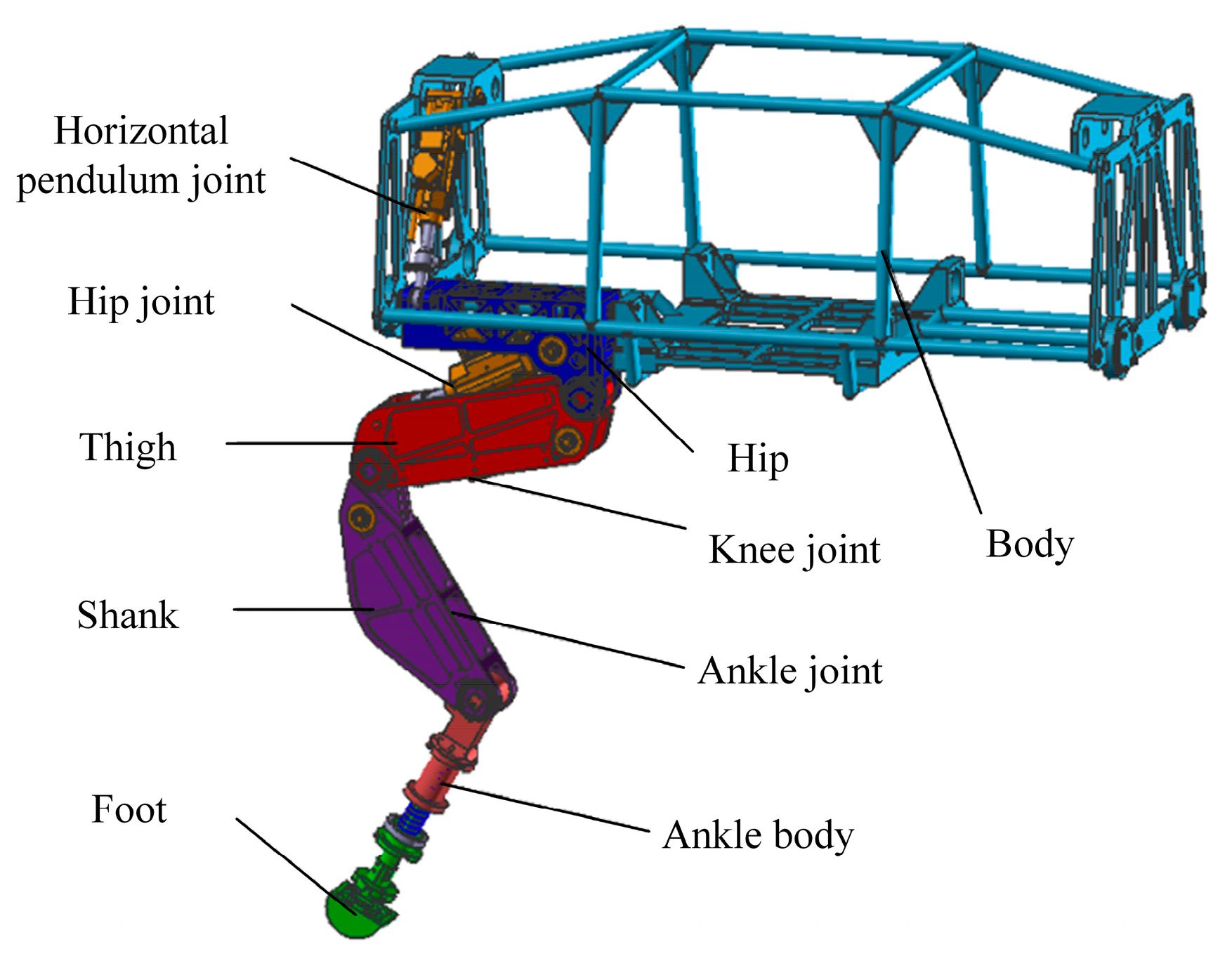
Based on a dog as a bionic object, a hydraulically actuated quadruped bionic robot is designed in this paper. Analyzing and simplifying the skeleton of the dog, each leg of the quadruped robot consists of five joints, including the yaw joint, hip joint, knee joint, ankle joint, and foot. The structure of single leg is shown in Figure 1. Apparently, the control system of the quadruped bionic robot is multiple inputs, multiple outputs, strong coupling, nonlinear, and complex. In order to realize rapid and smooth walking on uneven pavement, it is necessary to ensure the control system can real-time process multi-tasking, so as to realize unified and coordinated control of degrees of freedom of each joint [6].

Figure 1.
Structure of single leg for the hydraulically actuated quadruped bionic robot.
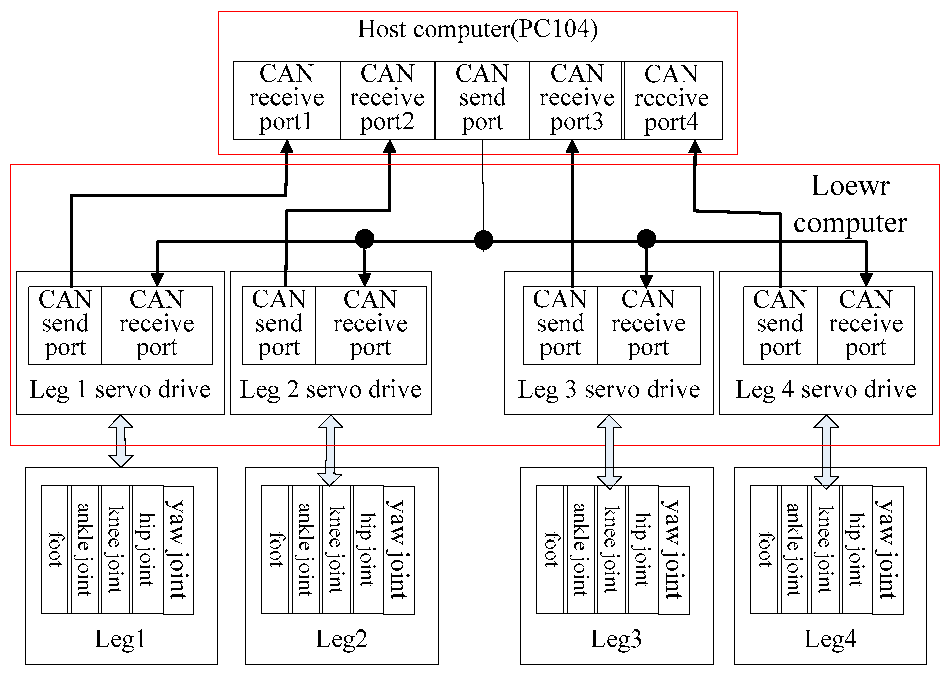
According to the actual structure of the hydraulically actuated quadruped bionic robot, hierarchical real-time control system is designed. Host computer uses general PC machine, and host computer is mainly responsible for the overall control of the robot, such as navigation, gait planning, and release control instruction. Lower computer uses four high-speed DSPs produced by TI company to control the movement of the four legs. They execute the data acquisition and processing for each joint, receive instruction information from the host computer, and select the appropriate control strategy to adjust attitude. Output instructions control the hydraulic actuator of each joint, realizing the normal operation of the hydraulic cylinder. Serial communication between host computer and lower computer adapts the CAN bus network. The host computer just gathers the state information of the moment and completes pose estimation and motion planning of the robot, then issues motion control commands of each joint, and the remaining work can be completed by the lower computer. The overall structure of the control system is shown in Figure 2.
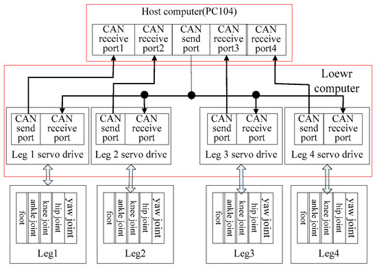
Figure 2.
Overall structure of control system.
The above two specific tasks of control system were completed by independent processors. They cooperate with each other to control the movements of the robot according to the predetermined control strategy. This paper focuses on the research and development of lower computer for hydraulically actuated quadruped bionic robot and designs a servo drive for each leg to achieve the unified and coordinated movement of each joint.
3. Hardware Design of Lower Computer
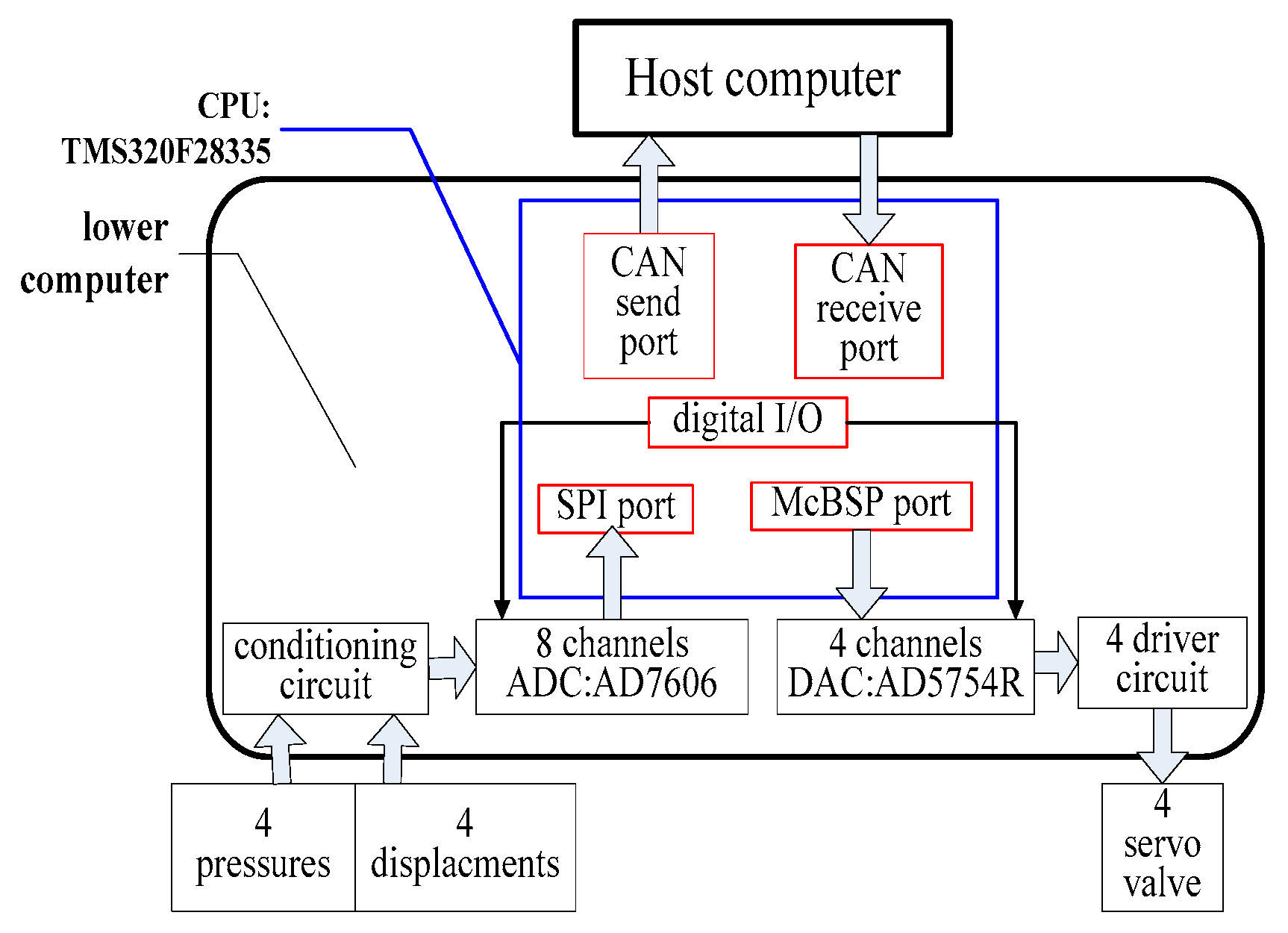
According to the actual motion of hydraulically actuated quadruped bionic robot, embedded DSP is used as the core control unit. Each leg designs a servo actuator and each servo-driven module can drive four hydraulic cylinders. The hardware components of hydraulic servo actuator are shown in Figure 3. The blue box is CPU of hydraulic servo actuator is TI digital signal processor (DSP), and the red box in the blue box is CPU peripherals. The boxes outside CPU are function modules.
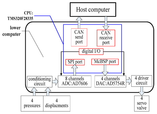
Figure 3.
Hardware compositions of lower computer.
As shown in Figure 3, the servo controller of hydraulically actuated quadruped bionic robot is mainly composed of DSP, A/D conversion module, D/A conversion module, and CAN communication module. Under normal working conditions, the feedback signals collected by the sensor are added into signal conditioning circuit to amplify. Then, the processed analog signals are added into the A/D conversion chip to convert the voltage signals into digital signals that the central processing unit can identify. After processing by DSP, the digital signals are converted into analog signals by D/A converter chip, and then, they are added into a V/I conversion circuit to complete the conversion and amplification from voltage signals to current signals, which are used to drive the servo valves and finish the coordinated motion of four joints.
As shown in above figure, the lower computer developed in this paper can complete the following tasks:
- Receive the control instructions from host computer according to certain protocol.
- Detect position and force of each joint.
- Complete the closed-loop control of hydraulic cylinders according to a predetermined control algorithm.
- Control the action of hydraulic cylinder according to the given instruction.
3.1. Selection of the Core Control Unit
Considering the application, price, and performance of the different series of DSP, we select TMS320F28335 which is optimal control platform in TI Company as a high performance microprocessor of quadruped bionic robot. TMS320F28335 is a floating-point DSP controller launched by TI Company.
The main frequency is up to 150 MHz, the instruction cycle is 6.67 ns, the core voltage is 1.9 V, and the I/O pin voltage is 3.3 V. Serial peripheral interfaces have two CAN modules, three SCI (serial communication interface) modules, two McBSP (multi-channel buffered serial port) modules, one SPI (serial peripheral interface) module, and one I2C (integrated circuit) bus. The SPI module and McBSP module can conveniently connect with high accuracy DAC and ADC directly [7].
The DSP also has the advantages of low cost, low power consumption, high performance, high speed, high peripheral integration, large data and program storage, and more precise A/D conversion [8]. In general, compared with the previous generation DSP, the average performances of TMS320F28335 increased by 50%, and it has compatibility with software of the fixed-point C28x controller, which simplifies software development, shortens development cycles, and reduces development costs.
3.2. Design of Sampling Module
The sampling module is responsible for collecting the actual output force and displacement data of each joint.
The DSP can identify and process digital signals, but the displacement or force of the hydraulic cylinder of each joint collected by sensor is continuous analog signals. So the controller needs to design a peripheral sampling circuit, and the collected analog signals are transmitted into the A/D conversion chip to convert the analog voltage signals into the digital signals that the central processing unit can recognize, and then, the digital signals are processed in the microprocessor.
3.2.1. Selection of A/D Conversion Chip
Considering the accuracy and sampling rate of conversion chip. The AD7606 developed by Analog Devices, Inc. (Wilmington, MA, USA), is chosen as an analog/digital conversion chip. AD7606 has 16-bit resolution, so it can meet the requirement of precision. The AD7606 is a simultaneous sampling analog-to-digital data acquisition system (DAS) with eight channels, completing the collection of the four displacement signals and four force signals. The AD7606 is supplied by a single 5 V and can accommodate ±10 V and ±5 V true bipolar input signals. Each part contains analog input clamp protection, a second-order antialiasing filter, a track-and-hold amplifier, a flexible digital filter, a 2.5 V reference and reference buffer, and high-speed serial and parallel interfaces [9]. In addition, the sampling rate is up to 200 kSPS for all channels, which can fully meet the requirement of the sampling rate.
AD7606 has two serial data output pins, DOUTA and DOUTB. A serial data output pin can output the conversion results of the four channels at the same time, but the four displacement signals and four force signals of each leg need to be collected; therefore, all eight channels of the AD7606 should be used to sample synchronously. All channels are sampled simultaneously when CONVST A and CONVST B are tied together. When the rising edge of CONVST is applied, BUSY reaches logic high and transitions low at the end of the entire conversion process. The falling edge considers the data output lines, DOUTA and DOUTB, out of three states, and the rising edge of SCLK clocks all subsequent data bits onto the serial data outputs, DOUTA and DOUTB [10].
3.2.2. Interface Circuit between TMS320F28335 and AD7606
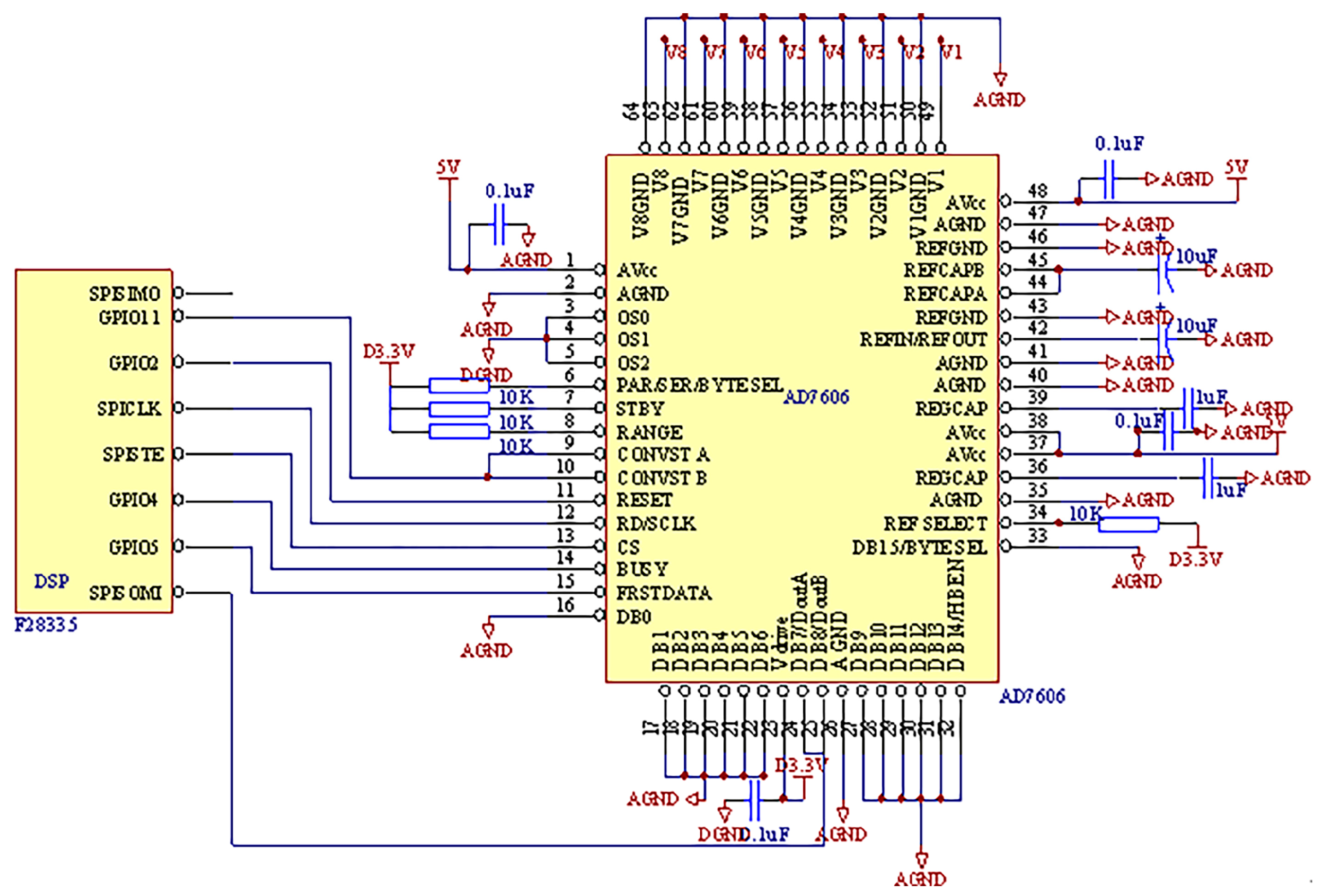
The communication between DSP and AD7606 is achieved by the SPI module. The circuit connection is shown in Figure 4.

Figure 4.
Hardware circuit of the sampling module.
As shown in Figure 4, the SPI operates in the master mode, and the SPICLK pin of TMS320F28335 is connected to SCLK pin of AD7606, so both share the serial clock. The SPISTE pin of TMS320F28335 is connected to the pin of AD7606. TMS320F28335 receives conversion results of eight channels from DOUTA and DOUTB of the AD7606 on the SPISOMI pin.
3.3. Design of Output Module
The output module is responsible for the output of the corresponding instruction to control the hydraulic-driven system of the leg and to achieve normal operation of the hydraulic cylinder.
The signals driving servo valve should be analog signals, and the signals processed by DSP are digital signals, therefore, it is necessary to convert digital signals to analog signals through D/A conversion chip, completing the coordinated movement of the joints.
3.3.1. Selection of D/A Conversion Chip
Each leg of hydraulically actuated quadruped bionic robot has four hydraulic cylinders, so the D/A conversion chip should have four outputs, and taking into account the accuracy of the D/A conversion chip to be larger than the resolution of the servo valve, the AD5754R developed by the Analog Devices, Inc, is selected as digital/analog conversion chip.
The AD5754R is quad, 16-bit serial input, voltage output, digital-to-analog converter (DAC). It operates from single supply voltage of +4.5 V up to +16.5 V or dual supply voltage from ±4.5 V up to ±16.5 V. The AD5754R uses a serial interface that operates at clock rate up to 30 MHz and is compatible with DSP and microcontroller interface standards [11].
For systems that contain several devices, the SDO pin can be used to daisy-chain several devices together. Daisy-chain mode can be useful in system diagnostics and in reducing the number of serial interface lines. The first falling edge of starts the written cycle, and SCLK is continuously applied to the input shift register when is low. If more than 24 clock pulses are applied, the data ripples out of the shift register and appears on the SDO line. This data is clocked out on the rising edge of SCLK and is valid on the falling edge. By connecting the SDO of the first device to the SDIN input of the next device in the chain, a multi-device interface is constructed. Each device in the system requires 24 clock pulses. Therefore, the total number of clock cycles must equal 24 × N, where N is the total number of AD5754R devices in the chain. When the serial transfer to all devices is complete, is considered high. This latches the input data in each device in the daisy chain and prevents any further data from being clocked into the input shift register. The serial clock can be a continuous or gated clock. A continuous SCLK source can only be used if is held low for the correct number of clock cycles [12].
3.3.2. Interface Circuit between TMS320F28335 and AD5754R
TMS320F28335 has only one SPI, and this interface has been used as the sampling module together with the AD7606. But TMS320F28335 has two McBSP, and the module can be expanded into the SPI module, after expanding the procedure is the same as SPI.
When the McBSP is configured as a master, the transmit output signal (DX) is used as the MOSI signal of the SPI protocol and the receive input signal (DR) is used as the MISO signal. CLKX is used as the SCLK signal and FSX is used as the CS signal.
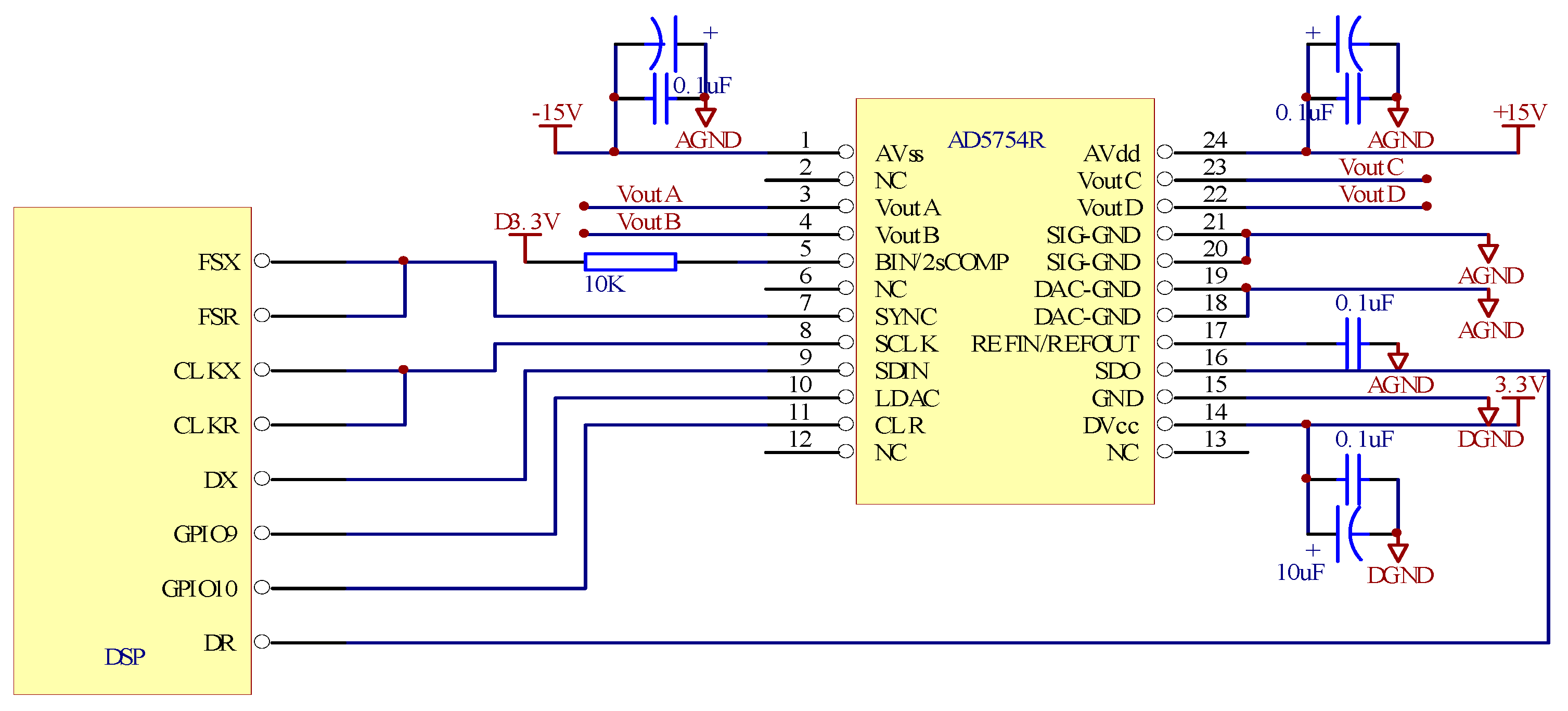
The communication between the DSP and the AD5754R is achieved by the McBSP module. The circuit connection is shown in Figure 5.
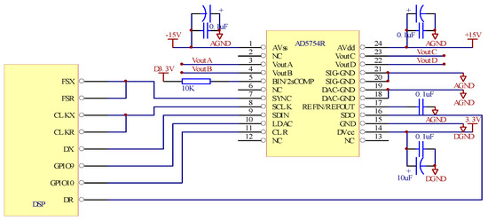
Figure 5.
Hardware circuit of output module.
As shown in Figure 5, the serial clock SCLK signal of the AD5754R is used as a transmit clock signal (CLKX) and a receive clock signal (CLKR) of DSP. Transmit frame sync pin (FSX) and receive frame sync pin (FSR) of DSP are connected to the serial interface frame sync pin of AD5754R, so that the transmit frame sync signal (FSX) and receive frame sync signal (FSR) of DSP keep synchronized with the frame sync signal of AD5754R. The data transmit pin (DX) of the DSP is connected to the data receive pin (SDIN) of AD5754R, the signals processed by DSP are outputted into AD5754R to be digital to analog conversion, and after conversion the signals are used to drive the servo valves.
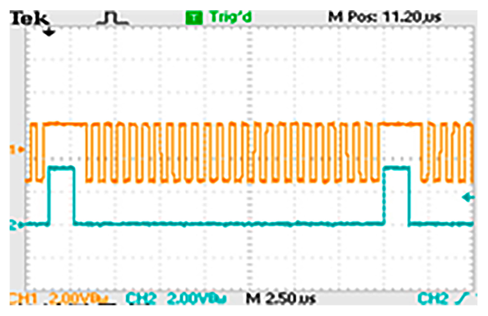
After debugging the timing of AD5754R is shown in Figure 6.

Figure 6.
Timing of AD5754R.
It can be seen from the above figure that each device in the system requires 24 clock pulses. Therefore, the total number of clock cycles must equal 24 × N, where N is the total number of AD5754R devices in the chain. Test results show that AD5754R can work normally, and the interface connections between AD5754R and TMS320F28335 are correct.
3.4. Design of CAN Communication Module
The communication between the host computer and the lower computer belongs to multi-point communications. It is high reliability and real-time transmission that is required in the communication system. CAN bus can meet these requirements. The interface circuit is easy to implement on the DSP, and the development is more convenient; therefore, CAN bus is chosen as the communication bus between host computer and lower computer of the hydraulically actuated quadruped bionic robot.
The enhanced Controller Area Network (eCAN) module implemented in the TMS320F28335 DSP is compatible with the CAN 2.0B standard (active). It uses the established protocol to communicate serially with other controllers in electrically noisy environments. With 32 fully configurable mailboxes and time stamping feature, the eCAN module provides a versatile and robust serial communication interface [13].
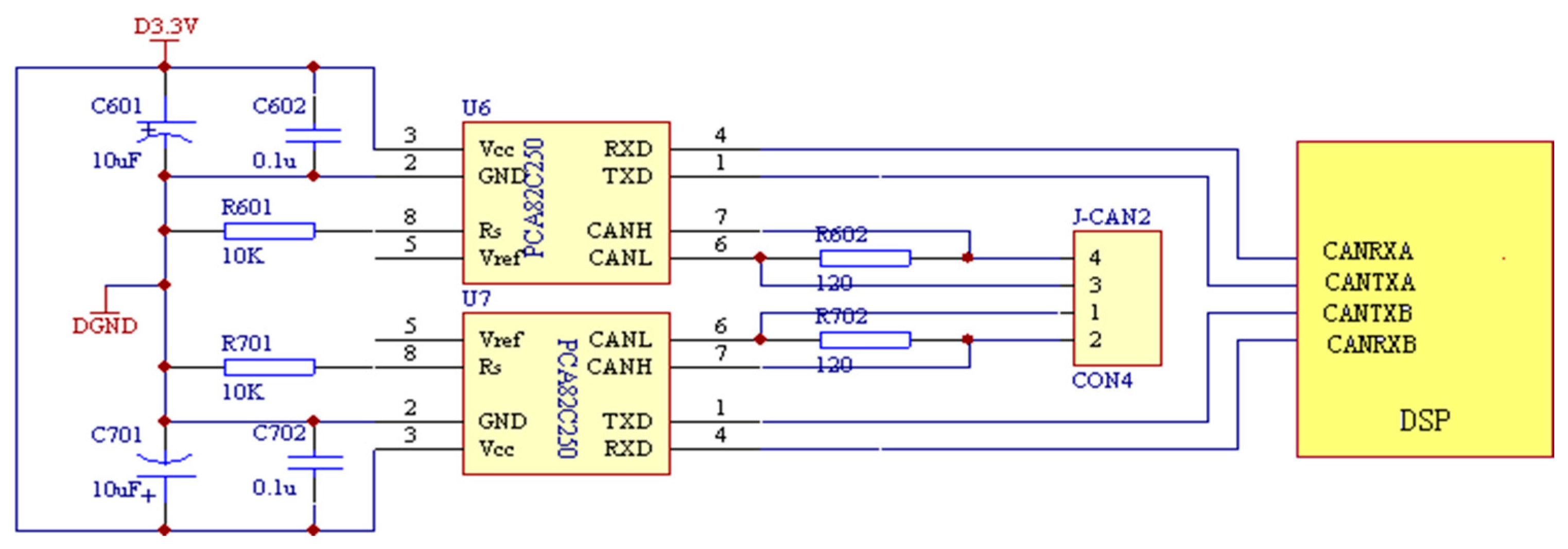
PCA82C250 is used as the CAN bus drive, and the hardware circuit is shown in Figure 7.

Figure 7.
Hardware circuit of CAN bus drive.
TMS320F28335 configures two CAN interfaces, i.e., the interface A receives the control commands from host computer and the interface B provides feedback of the status information from drives and servo units, and the baud rate is 1 Mbps. Each leg of hydraulically actuated quadruped robot has a controller, each controller has two CAN interfaces, used to receive instructions and transmit data, respectively. One CAN port on host computer is used to send instructions, which constitutes instruction sending CAN network together with CAN A of four legs controller. Four CAN ports on host computer are used to receive data, which constitute feedback data receiving network together with CAN B of four legs controller. The communication structure is shown in Figure 2.
4. Research of Control Strategy
The traditional PID is difficult to reconcile the contradiction between rapidity and stability, and the robustness is not good enough in the case of parameter variations and external interference. Fuzzy control depends on the error and error rate, but they cannot adapt to the requirements of the different controlled objects when both are of equal degrees of weight, so the adjustment factor is introduced. The online self-adjust correction factor is actually the weighted control for the error and error rate, reflecting the automatic adjustment of the weight according to the size of the error. Fuzzy control is essentially a proportional plus derivative control, and static characteristics are bad. Therefore, a composite controller composed of PID controller and fuzzy controller is put forward, and the PID control is implemented in the vicinity of the working point (static), where the integration can eliminate static error; fuzzy control plays a regulatory role in the remote area from the working point (the dynamic process of large errors), so that the oscillation near the working point can be eliminated and the accuracy of the system can be improved [14].
4.1. Fuzzy–PID Compound Control Algorithm
In combined PID controller with fuzzy controller, the fuzzy control with a self-adjust correction factor is mainly executed in the remote area from the working point; the PID control is mainly executed in the vicinity of the working point. Fuzzy inference is used to complete the “switch” to ensure the smooth transition of the two controllers, which achieves the complementary advantages of the two controllers and significantly improves the control performances.
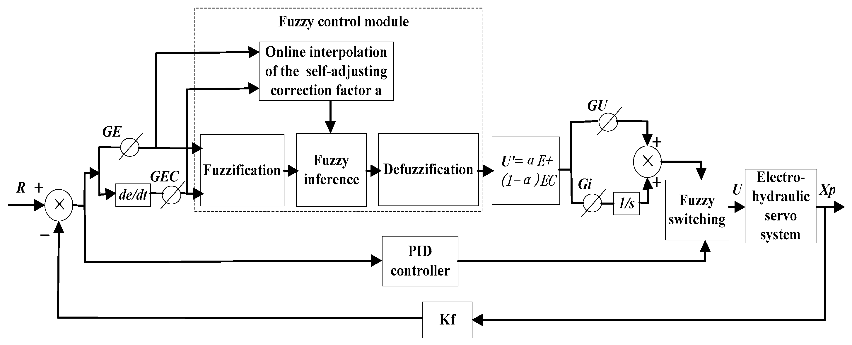
The control system of the fuzzy–PID composite controller is shown in Figure 8. The system controller consists of PID linear controller and fuzzy controller based on the online interpolation correction factor. Two control signals UPID and Ufuzzy are smoothly switched according to the fuzzy membership function SE, SEC, and the fuzzy switching rules, and the composite signal U is produced to keep track of the set value R.

Figure 8.
Fuzzy–PID composite control systems.
In Figure 8, GE and GEC are the quantization factors of E and EC. GU and Gi are the proportion factor and integration factor, respectively. These parameters can be optimized using ITAE performance index.
wherein, J is the integral area size of the weighted error function. The performance index can better reflect the response speed, regulation time, steady-state error, and overshoot of the system.
The parameters of the PID controller are debugged repeatedly by trial and error method to optimize the balance response speed, stability, and other indicators to achieve the control requirements. The parameters include Kp (proportion gain), Ki (integration gain), and Kd (differential gain).
4.1.1. Design of Fuzzy Controller Based on the Online Interpolation Correction Factor
In the control system based on the online interpolation correction factor, the input is the error E and error rate EC, and the output is the correction factor α. In a continuous system, the error rate of change EC(t) can be expressed by \frac{dE(t)}(dt), that is, EC represents the speed at which the deviation E changes. In this paper, the error E and the error change rate EC are classified into seven language values, namely NB, NM, NS, 0, PS, PM, and PB (see Table 1). Correction factor α is assigned to five linguistic values, namely, VS, S, M, B, and VB.

Table 1.
Fuzzy rules of the online self-adjust correction factor.
The fuzzy domain and fuzzy set are defined as follows:
- α’s fuzzy sets: {VB, B, M, S, VS}
- α’s domain: {1, 0.75, 0.5, 0.25, 0}
The membership function of the output variable is as follows:
The following control rules are adopted.
Because the value of the correction factor can directly reflect the weighted degree of error E and error rate EC, so it can truthfully reflect the thinking characteristics of the operator manual control. That is, when E and α are too large, the main function of the controller is to eliminate the error. When EC is too small and α is too small, the control function is mainly to eliminate the change of error and keep the system stable. The fuzzy rules of the online self-adjust correction factor are shown in Table 1 based on the experience of experts.
Fuzzy judgment of α adapts the center of gravity method. In order to avoid the steady-state error and the steady-state chattering phenomenon of the fuzzy quantification, online interpolation operation is performed for the correction factor α.
According to the expansion of Taylor binary function, when , , the corresponding α can be approximated as follows:
4.1.2. Design of Fuzzy Switching
In this paper, a fuzzy switching method is used to ensure the smooth transition between fuzzy control and linear PID control, avoiding undesirable disturbance caused by the conventional switching methods.
The fuzzy inference rule for switching between PID control and fuzzy control is as follows:
IF E(k) is SE and EC(k) is SEC THEN “output” is UPID. Else “output” is Ufuzzy.
Wherein, UPID is the output of the PID control, and Ufuuzy is the output of the fuzzy control. SE and SEC are the membership functions of the fuzzy variables E and EC, respectively.
At the k moment, the inputs are E and EC, and the output of Fuzzy–PID composite controller is as follows:
Among
4.1.3. Simulation of Fuzzy–PID Composite Controller
Linear PID controller and Fuzzy–PID composite controller are used in electro-hydraulic servo system for simulation study. The gain and value of fuzzy controller and PID controller in Fuzzy–PID compound controller are shown in Table 2. The input is a unit step signal.
Table 2.
Gain and value of Fuzzy–PID composite controller.
The drive system of the hydraulic quadruped robot is a typical valve-controlled cylinder servo system. Based on the closed-loop identification method, this study uses the ARX model and the state space model to identify the system and selects the model with the highest fit as the mathematical model of the valve-controlled hydraulic cylinder (as shown in Formula (8)).
The simulation uses the ode45 algorithm supplied by the SIMULINK, and the sampling frequency is 1000 Hz. The simulation results are shown in Figure 9.
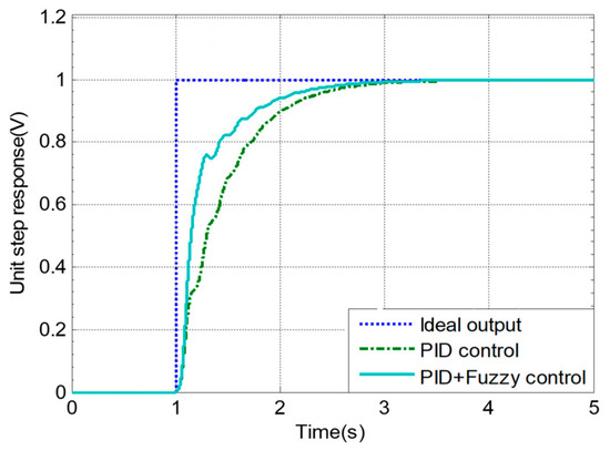
Figure 9.
Unit step response of electro-hydraulic servo system.
Figure 9 shows the unit step responses of the system under the three control methods. The simulation results show that the Fuzzy–PID composite control method not only improves the speed of the transient response of the system but also overcomes the steady-state error caused by traditional fuzzy control.
4.2. Software Design of Controller
The software of the controller is written in C language under DSP integrated development environment CCS. In order to achieve the functions of quadruped bionic robot, the software of integrated driven controller must include the main program, data collection module, CAN transmission module, closed-loop arithmetic module, and drive control module. The data collection module is used to complete the real-time detection of state parameters, such as displacements and forces for each joint. The CAN transmission module is responsible for sending the movement status information of the joint to the host computer, and promptly accepting the instructions from host computer. The closed-loop arithmetic module completes the correlation calculations of the position and force in accordance with the motion instructions and the actual state differences. The drive control module completes the output control of the servo valves according to the closed-loop calculation results, so that each joint of the robot can motion stably in accordance with the given movement commands.
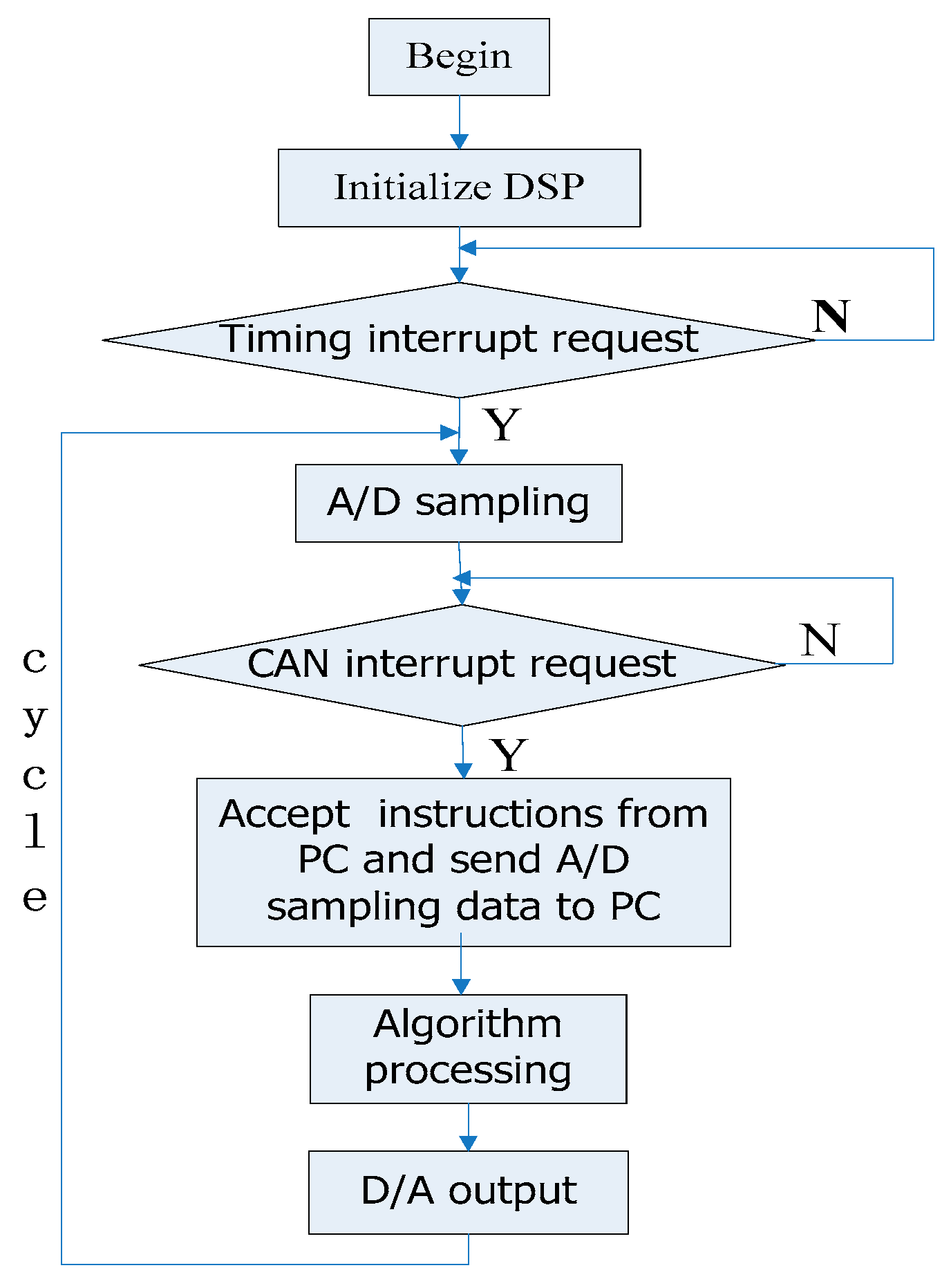
The procedure of the software is shown in Figure 10, mainly to complete the system initialization, each module call, and the determination of processes. The data collection adapts a timer interruption, and the cycle of the timer is 50 μs. The CAN communication programs use CAN interruption to receive and transmit data. The controller uses a Fuzzy–PID compound control algorithm. In practical applications, the system parameters can be online-adjusted according to control experience.
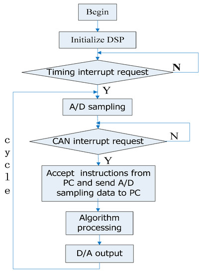
Figure 10.
Procedure of the software for the lower computer.
5. Experimental Testing
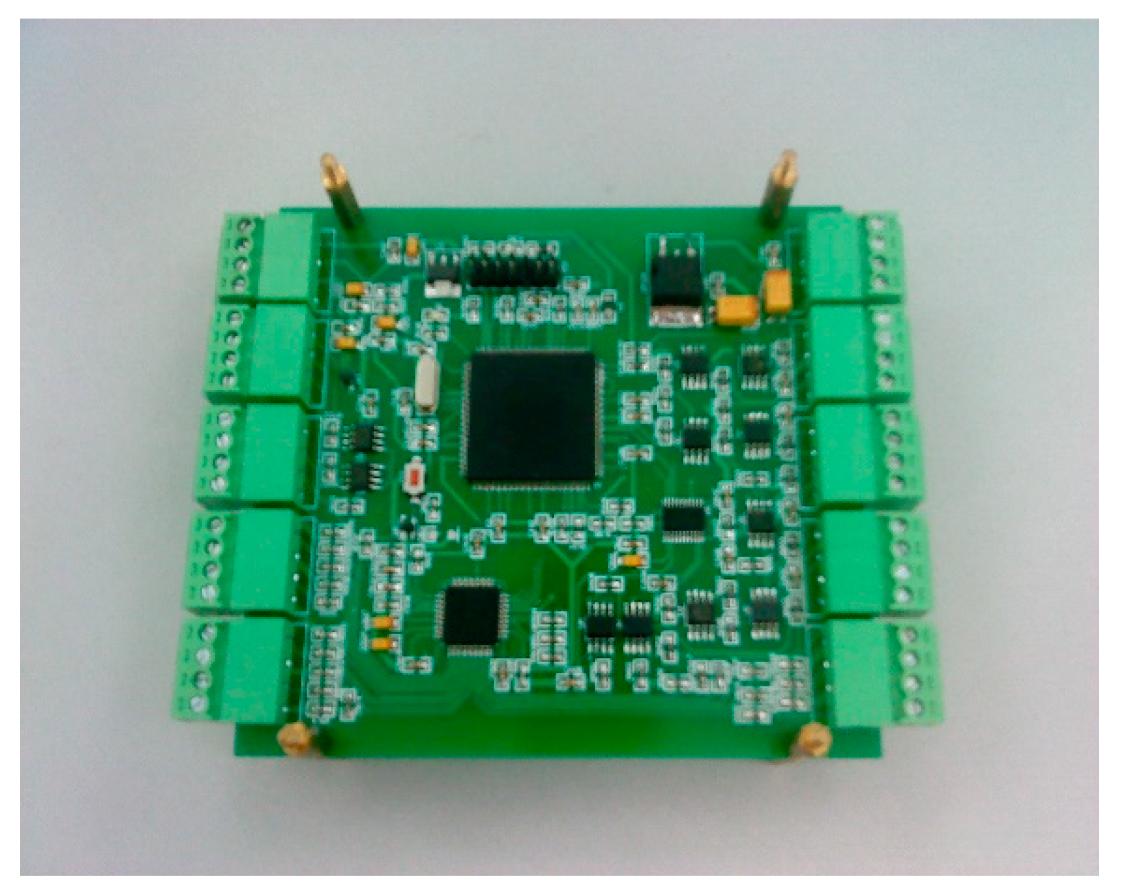
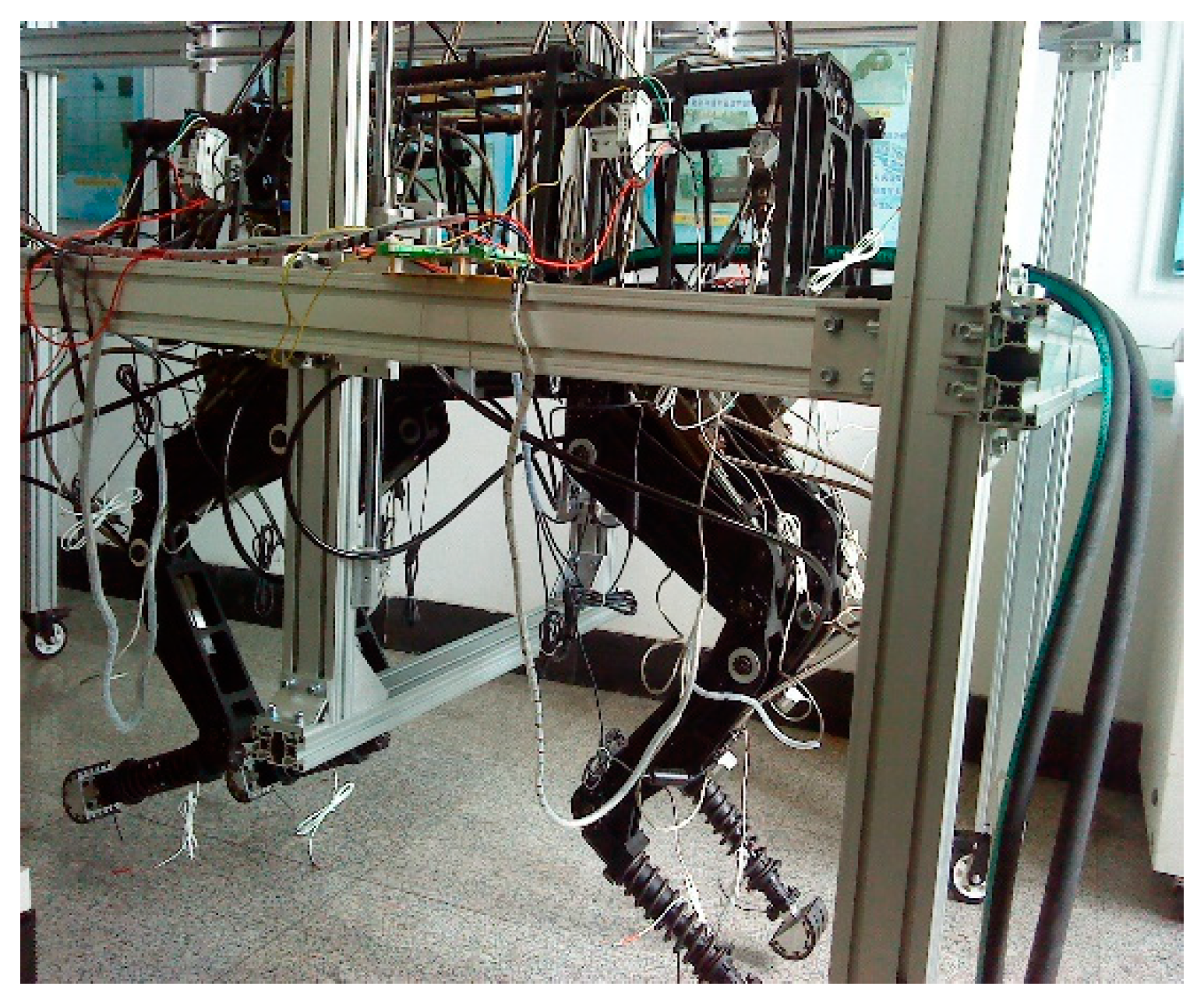
The lower computer developed and designed in this paper is shown in Figure 11. This lower computer is installed on body of the quadruped robot to test the performance. Under the initial posture, the body height is 1.2 m, the length and width of the body are 1 m and 0.4 m, respectively, and the weight is 65 kg (excluding the hydraulic power source). In order to facilitate testing, hydraulic energy is supplied by the fixed hydraulic pump station, instead of an independent centralized hydraulic source. The test platform is shown in Figure 12. The experiments mainly test the movements of the joints, and the whole process of the motion is displacement servo. The rated flow of servo valve is 11.5 ± 0.8 L/min, and the working pressure is 10 Mpa.

Figure 11.
Lower computer of the hydraulically actuated quadruped bionic robot.

Figure 12.
Test platform of the hydraulically actuated quadruped bionic robot.
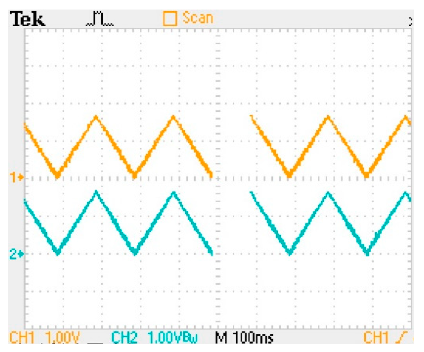
Because the four legs have identical actuator, consider the left-hind leg as an example for testing. Each actuator can drive four joints, in order to show the effect of the control. Consider the knee joint for example, given a triangular wave signal, knee joint performs the appropriate action by the lower computer. The motion curves of the knee joint observed using an oscilloscope are shown in Figure 13.
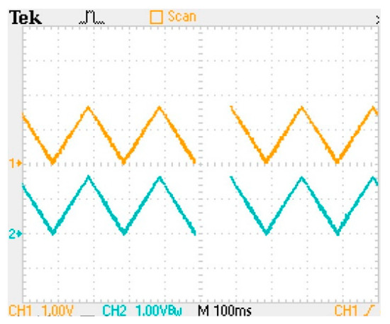
Figure 13.
Motion curves of the knee joint.
In Figure 13, the curve 1 is the given triangular wave signal, and curve 2 is the output signal of the actuator. It can be seen from the experimental curves that the output curve can well follow the given curve, and the error is very small (the signal amplitude attenuation rate is about 2.4%), and there is no delay.
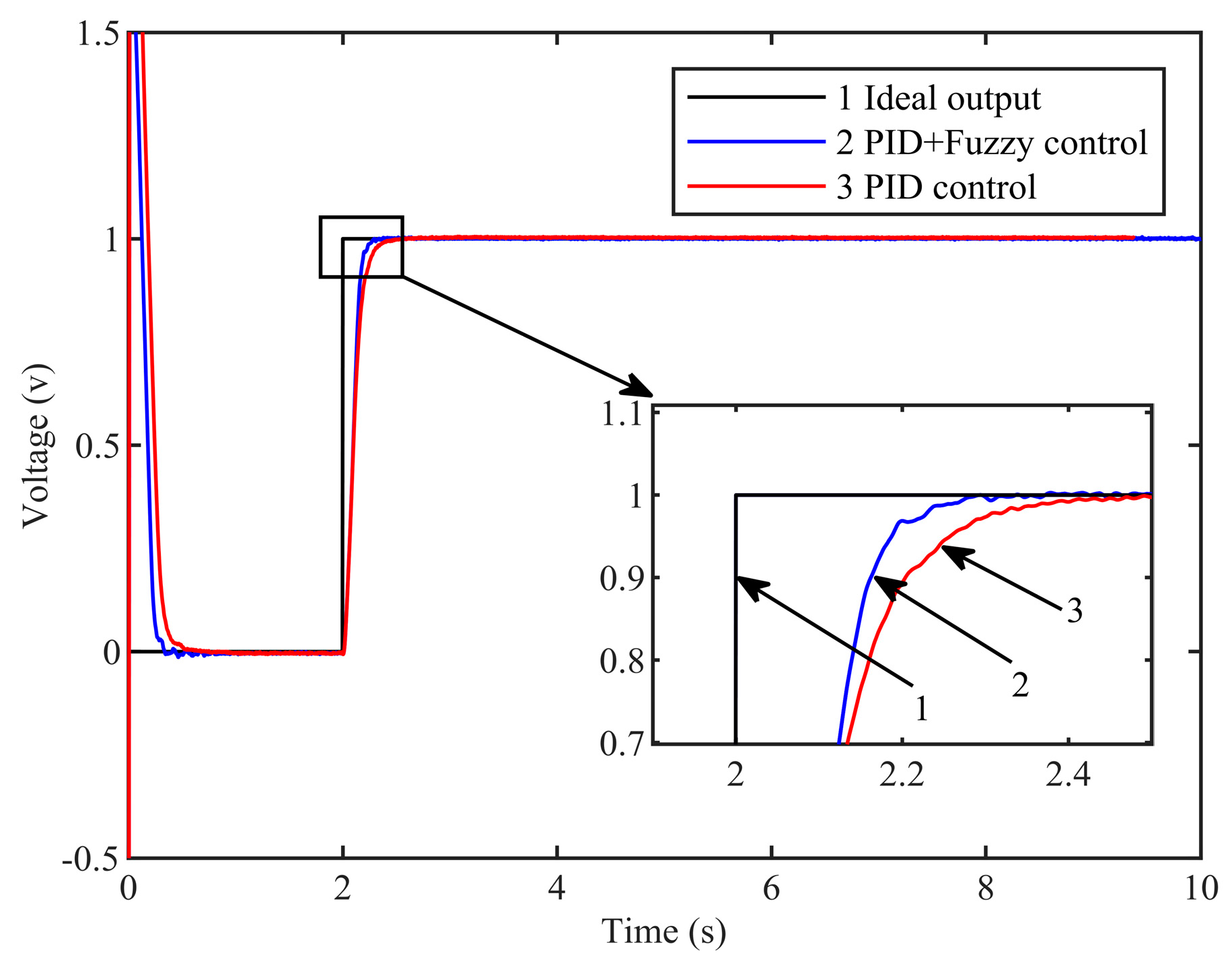
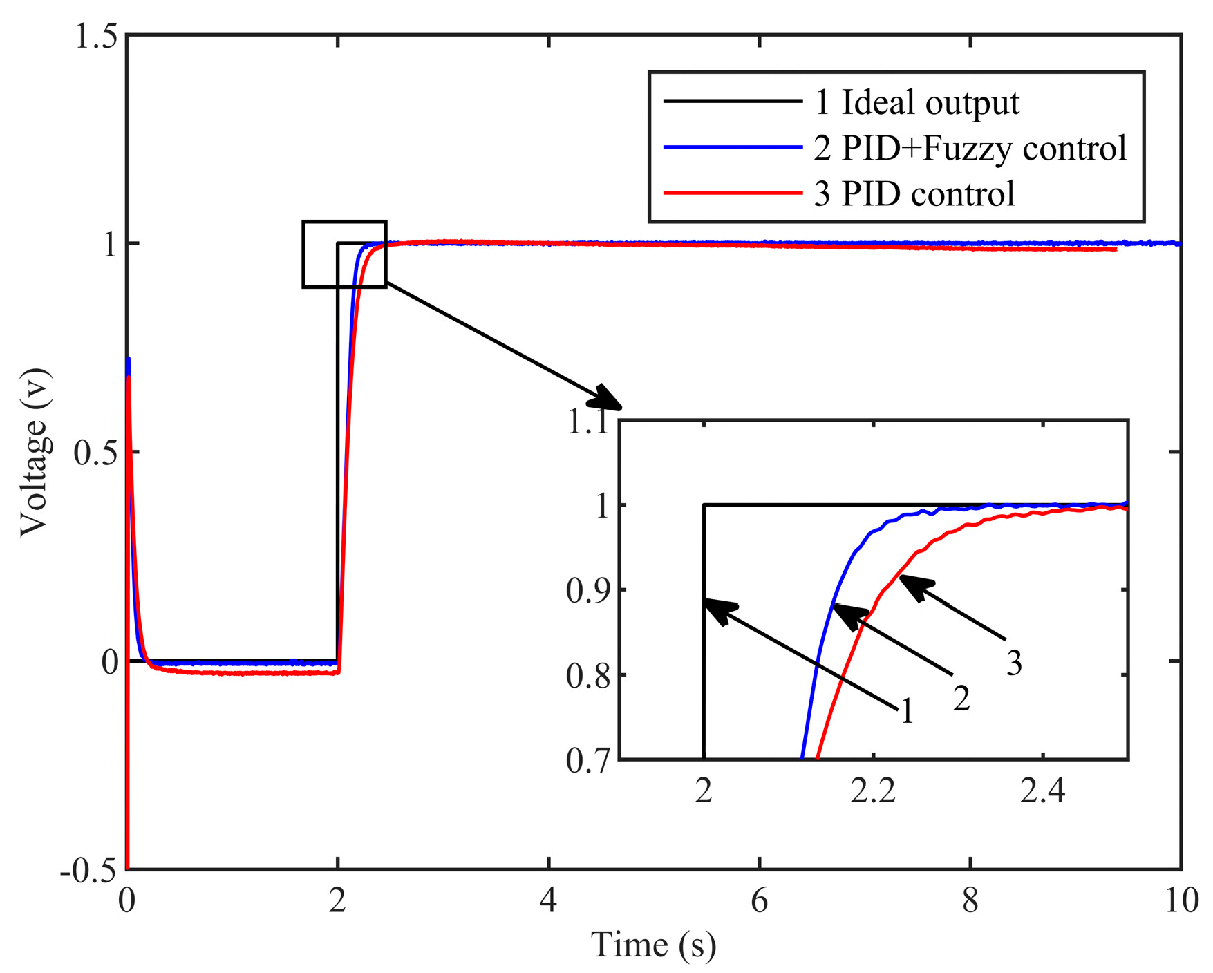
Then, the step signal is inputted to the ankle joint and the knee joint, and the test system using the linear PID controller and the Fuzzy–PID compound controller are tested, respectively. The motion response curve of the ankle joint (Figure 14) and the motion response curve of the knee joint (Figure 15) were obtained. Curve 1 in the two figures is a given step signal. Curve 2 is the response curve of the Fuzzy–PID compound controller designed in this paper. Curve 3 is the response curve under the linear PID controller.
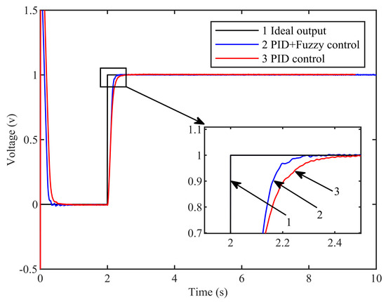
Figure 14.
The unit step response curve of the knee joint.
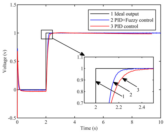
Figure 15.
The unit step response curve of the ankle joint.
It can be seen from the output curve of the knee joint that the steady-state error of the traditional PID control method is about 0.5%, while the steady-state error of the Fuzzy–PID control method is about 0.05%. It can be seen from the output curve of the ankle joint that the steady-state error of the traditional PID control method is about 0.23%, while the steady-state error of the Fuzzy–PID control method is about 0.02%. It is not difficult to see that the test results of the Fuzzy–PID controller designed in this paper have smaller steady-state error and higher control precision.
In addition, in the response curve of the knee joint, the adjustment time of the linear PID control method is about 0.7 s, and the adjustment time of the Fuzzy–PID control method is about 0.43 s. In the ankle joint response curve, the adjustment time of the linear PID control method is about 0.71 s, and the adjustment time of the Fuzzy–PID control method is about 0.45 s. By comparing the adjusting time, we can know that the adjusting time of the Fuzzy–PID controller designed in this paper is faster, that is, the response speed is faster. In short, the experimental test results have verified the simulation results well. That is to say, the Fuzzy–PID compound control method obviously improves the transient response speed of the system, and the steady-state error is smaller than the traditional linear PID control method.
It is shown that the lower computer developed in this paper has fast response speed and high control precision. It can be seen from the experimental process that the four-legged robot can do the movement freely and stably, without any mechanical interference. The experimental results show that the lower computer developed in this paper can well meet the control requirements for hydraulically actuated quadruped robot, and the software and hardware of the controller are very reasonable.
6. Conclusions
In order to achieve the control for quadruped bionic robot driven by 16 hydraulic cylinders, a control system based on DSP is designed. TMS320F28335 is selected as master chip and an outside control circuit is built: one AD7606 is expanded to build the A/D sampling circuit; one AD5754R is expanded to build the drive control module; and two PCA82C250s are expanded to build the communication module. The Fuzzy–PID composite control algorithm is used, which not only shortens the response time but also improves the stability of the system. The design of the control system is completed from hardware to software, and the detection, control, and drive of each joint is achieved. It can be seen from the experiment that the control system designed in this paper is reasonable, and it is able to effectively control the joints of the quadruped robot and has a strong scalability, which can meet the basic requirements of a control system of an autonomous mobile robot.
Author Contributions
B.G.: provided research topics, provided research ideas, and guided research content. Y.W.: sorted the research data and prepared the manuscript. W.H. and S.X.: provided research equipment and recorded research data. All authors have read and agreed to the published version of the manuscript.
Funding
This work was supported by the National Natural Science Foundation of China (Grant No. 52075134).
Institutional Review Board Statement
Not applicable.
Informed Consent Statement
Not applicable.
Data Availability Statement
Not applicable.
Conflicts of Interest
The authors declare no conflict of interest, financial or otherwise.
References
- Singh, R.; Bera, T.K. Walking Model of Jansen Mechanism-Based Quadruped Robot and Application to Obstacle Avoidance. Arab. J. Sci. Eng. 2020, 45, 653–664. [Google Scholar] [CrossRef]
- Biswal, P.; Mohanty, P.K. Development of quadruped walking robots: A review. Ain Shams Eng. J. 2021, 12, 2017–2031. [Google Scholar] [CrossRef]
- Pajaziti, A.; Bajrami, X.; Paliqi, A. Path Control of Quadruped Robot through Convolutional Neural Networks. In Proceedings of the 18th International-Federation-of-Automatic-Control (IFAC) Conference on Technology, Culture and International Stability (TECIS), Baku, Azerbaijan, 13–15 September 2018; pp. 610–615. [Google Scholar]
- Nicolai, J.; Castagnet, T. Flexible micro-controller based chopper driving a permanent magnet DC motor. In Proceedings of the 1993 Fifth European Conference on Power Electronics and Applications, Brighton, UK, 16 October 1993; pp. 200–203. [Google Scholar]
- Sun, Y.; Li, S.H.; Ramezani, M.; Balasubramanian, B. DSP chip options contract and expand. Energies 2019, 12, 2558. [Google Scholar] [CrossRef]
- Chung, J.W.; Park, I.W.; Oh, J.H. DSP Implementation of a Neural Network Vector Controller for IPM Motor Drives. Adv. Robot. 2010, 24, 277–298. [Google Scholar] [CrossRef]
- Andrew, X.R.I.; Anand, M.; Sivakumar, P. Modeling and analysis of emulator for distributed generation sourced smart grid using digital signal controller (TMS320F28335). In Proceedings of the 2011 IEEE PES International Conference on Innovative Smart Grid Technologies, Trichy, India, 1 December 2011. [Google Scholar]
- Li, Z.J.; Qie, W.F.; Zhang, L.; Ren, X.H. Research of power system stabilizer based on TMS320F28335. Power Syst. Prot. Control 2011, 39, 112–116. [Google Scholar] [CrossRef]
- She, X.P.; Xiong, J.Q. Multi-channel electrical power data acquisition system based on AD7606 and NIOSII. In Proceedings of the 2011 International Conference on Electrical and Control Engineering, Jingzhou, China, 16–18 September 2011. [Google Scholar]
- Wang, B.J.; Miao, L.; Dong, H.Y.; Li, H. Design of dynamic synchronous multi-channel data acquisition system for lung sound based on FPGA. In Proceedings of the 2012 IEEE International Conference on Information and Automation, Shenyang, China, 23 July 2012. [Google Scholar]
- Wang, P.F.; Cui, W.B.; Chen, J. Application of AD574 in IC test system. Microelectron. Technol. 2000, 28, 58–61. [Google Scholar]
- Hou, F.Y.; You, H.Y. The data processing program for AD574 converting. Tech. Autom. Appl. 2007, 26, 117–118. [Google Scholar] [CrossRef]
- Godoy, E.P.; Lopes, W.C.; Sousa, R.V.; Porto, A.J.V.; Inamasu, R.Y. Modeling and simulation of can-based communication networks. Rev. Controle Automação 2010, 21, 425–438. [Google Scholar] [CrossRef]
- Kazemian, H.B. Developments of fuzzy PID controllers. Expert Syst. 2005, 22, 254–264. [Google Scholar] [CrossRef]

Disclaimer/Publisher’s Note: The statements, opinions and data contained in all publications are solely those of the individual author(s) and contributor(s) and not of MDPI and/or the editor(s). MDPI and/or the editor(s) disclaim responsibility for any injury to people or property resulting from any ideas, methods, instructions or products referred to in the content. |
© 2023 by the authors. Licensee MDPI, Basel, Switzerland. This article is an open access article distributed under the terms and conditions of the Creative Commons Attribution (CC BY) license (https://creativecommons.org/licenses/by/4.0/).