Abstract
With unique electromagnetic properties, metamaterials (MTMs) provide more freedom for antenna design, particularly with the combination of active-device-enabling effective tuning. By integrating the active device and the periodical cells of MTMs, the electromagnetic characteristics of individual cells can be manipulated independently, thereby realizing multiple tunable states for MTM antennas consisting of several periodical cells. In this paper, we employ active devices such as PIN diodes to each periodical cell to tune each cell independently, thereby realizing 36 tunable zeroth-order resonances (ZORs) for the metamaterial antenna with three cells in a frequency range of 4.48–5.34 GHz. Moreover, each ZOR has a bandwidth as narrow as 0.09 GHz, indicating that the tunable ZOR antenna can be potentially applied to 5G Narrowband Internet of Things (NB-IoT).
1. Introduction
As an artificial structure, metamaterials (MTMs) can realize unusual electromagnetic properties such as negative permittivity εr, negative permeability μr, inverse Cerendorf effect, and inverse Doppler effect [1,2,3]. Nowadays, MTMs are booming in many research directions, including composite right/left-handed transmission line (CRLH-TL) [4,5], frequency selective surface (FSS) [6,7,8], high-impedance surface (HIS) [9,10], and spoof surface plasmon polaritons (SSPPs) [11,12], which cover the frequency spectrum from the microwave to the visible light band. The MTM enriches antenna performance as well, particularly with active devices integrated to the periodical cells. The MTM antenna based on CRLH-TL has periodic characteristics, of which periodical cells are independent. Hence, loading active devices in cells can tune the MTM consisting of periodical cells with many states for a variety of tunable characteristics, such as tunable frequencies, polarizations, radiation patterns, etc. The MTM antennas in [13,14] use varactors to achieve tunable resonant frequencies. In [15,16], the proposed coding MTMs, digital MTMs, and programmable MTMs, which employ active devices to periodical cells, have very good application value for realizing the resonant frequency and the radiation pattern tunability of antennas. The traditional leaky wave antenna (LWA) has many limitations in beam scanning. For example, it can only scan in one direction, or the broadside scanning is invalid [17]. Nevertheless, the combination of MTMs and LWAs offers a solution to overcome these shortcomings [18]. With loading active devices, the active MTM LWA can achieve beam scanning at a fixed frequency, which saves spectrum resources and meets the requirements of modern communication. The LWAs proposed in [19,20,21,22] all use PIN diodes or varactors to achieve radiation pattern tunability at a fixed frequency band. The MTM antennas in [23,24] utilize active devices to achieve multi-polarization tunability. The tunable characteristics of active MTM antennas have great significance in the application of MTM antennas.
When the propagation constant β of the MTM antenna is zero, the resonance order is zero, which is called zeroth-order resonance (ZOR). When the MTM antenna is in ZOR, its resonant frequency is determined by the cell and is independent of the overall physical size of the antenna. The number of resonances corresponds to the number of cells. Therefore, by loading the active device into the cell, the cell can be tuned to achieve the tuning of the ZORs. With the introduction of CRLH-TL theory [4,5], ZOR can be tuned through embedded micro-electro-mechanical systems (MEMS), varactors, or PIN diodes. Ref. [25] uses MEMS as active devices to realize tunable ZORs in both “on” and “off” states. Refs. [26,27,28,29,30,31,32,33] utilize varactors as active devices, and ZORs can be tuned by tuning the bias voltage applied to varactors. In [34,35], PIN diodes are used to achieve ZOR frequency tunability, but are limited to only two tunable states.
In general, most of the current research on ZOR frequency tuning uses varactors as active tunable devices. The advantage is that it can achieve the frequency tuning of multiple ZORs, but the varactor requires a high-bias voltage with a large power consumption. From the perspective of reducing power consumption, PIN diodes only need a low-bias voltage. Moreover, using PIN diodes as active devices in the MTM antennas consisting of many cells allows the antenna to achieve multiple ZOR tuning, rather than several limited tunable states, which obviously extends their application scenarios in IoT (Internet of Things). The Internet of Things (IoT) is a technology that connects various objects through the Internet. Its essence lies in the exchange of information and communication between objects. The core of the IoT is to use the Internet to connect objects to each other and realize data transmission and communication. By installing sensors in objects such as power grids, railways, tunnels, highways, bridges, water supply systems, and oil and gas pipelines, and integrating with the existing Internet, the IoT realizes interconnection between objects. It can be seen in many fields such as intelligent transportation, government work, smart home, environmental monitoring, street lighting management, elderly care, and intelligence collection [36,37,38,39]. Narrowband Internet of Things (NB-IoT), as an important branch of the IoT, has a series of characteristics such as flexible deployment, narrow bandwidth, fast transmission speed, and low energy consumption. At present, most of the IoT technology applications are NB-IoT. The frequency-tunable antenna is mainly used in scenes that require multiple operating frequencies, and its operating frequency is discrete or continuous in a certain frequency range. Since the NB-IoT usually requires multiple application scenarios, and the operating frequency corresponding to each application scenario is different, as shown in Figure 1, the frequency-tunable antenna has a good application prospect in the NB-IoT.

Figure 1.
NB-IoT requires frequency-tunable antennas.
In this paper, a ZOR tunable active MTM antenna based on CRLH-TL is proposed, in which PIN diodes are used as the active device in these three cells. By changing the voltage of the PIN diode, multiple ZORs can be tuned from 4.48 GHz to 5.34 GHz with a narrow bandwidth of around 0.86 GHz. Since the antenna has narrowband characteristics, it can be applied to NB-IoT for managing the production and life of the intelligent network in a dynamic way.
The organization of this paper is as follows: Section 2 introduces the design and simulation of the MTM antenna cell. Section 3 presents the simulation of the antenna, including full-wave simulation and field-circuit co-simulation. Section 4 illustrates the experimental validation of the antenna, including the measurement of the S-parameter and the radiation pattern. Section 5 provides the conclusion.
2. Cell Design and Simulation
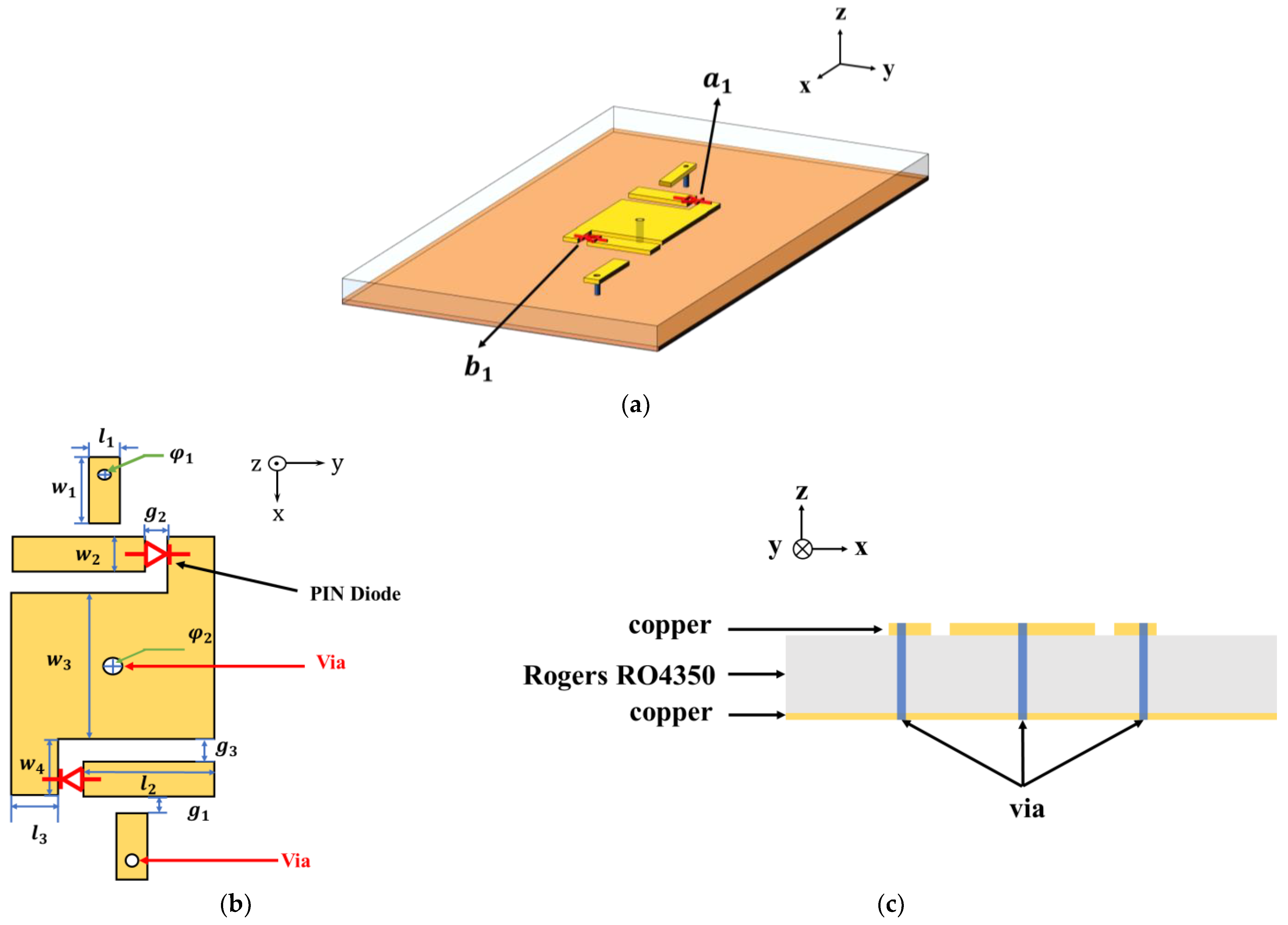
As shown in Figure 2, the cell is composed of a main patch, a via in the middle, and parasitic patches in the x-axis and y-axis. The gap between the main patch and the y-axis parasitic patch is used to load PIN diodes and , and the gap between the x-axis parasitic patch and the y-axis parasitic patch is loaded with the isolation inductor. In the cell, the DC bias circuit is formed of a via below the x-axis parasitic patch and a via below the main patch. The dielectric substrate is Rogers RO4350 () with a thickness of 1.524 mm. The top layer is the MTM antenna, and the bottom layer is the antenna ground. The size of the antenna cell is provided in Table 1.
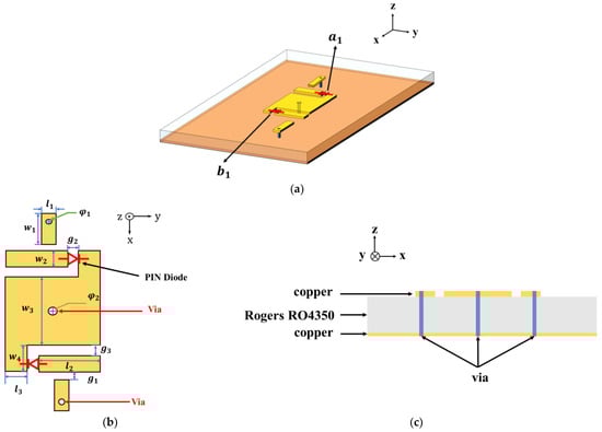
Figure 2.
Design model of the proposed antenna cell: (a) 3D model; (b) top view; (c) side view.

Table 1.
Dimensions of the proposed antenna cell (mm).
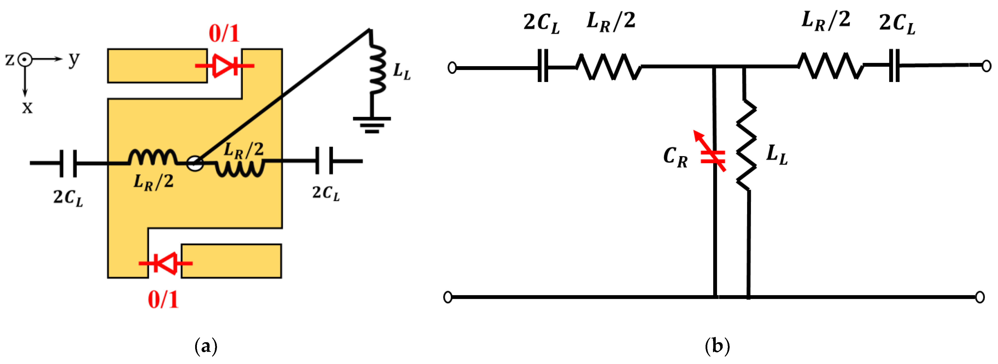
As shown in Figure 3, the CRLH-TL theory is used to analyze the equivalent circuit of the antenna cell. The gap between the antenna cells can be equivalent to the capacitance CL. The main patch is equivalent to the inductance LR and the grounding capacitance CR. The grounding hole in the center of the main patch is equivalent to the inductance LL. The MTM antenna has three cells and operates at the open terminal case, so its ZOR frequency is equal to the parallel resonant frequency [4].
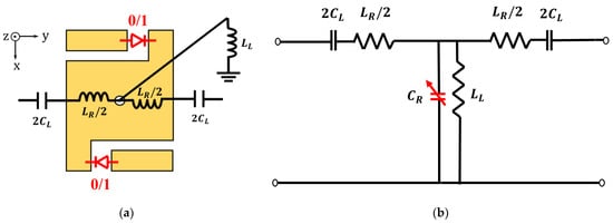
Figure 3.
Antenna cell: (a) Equivalent model of parameters; (b) equivalent circuit model.
From Equation (1), it can be seen that the ZOR frequency of the MTM antenna can be tuned by changing the value of the capacitance CR.
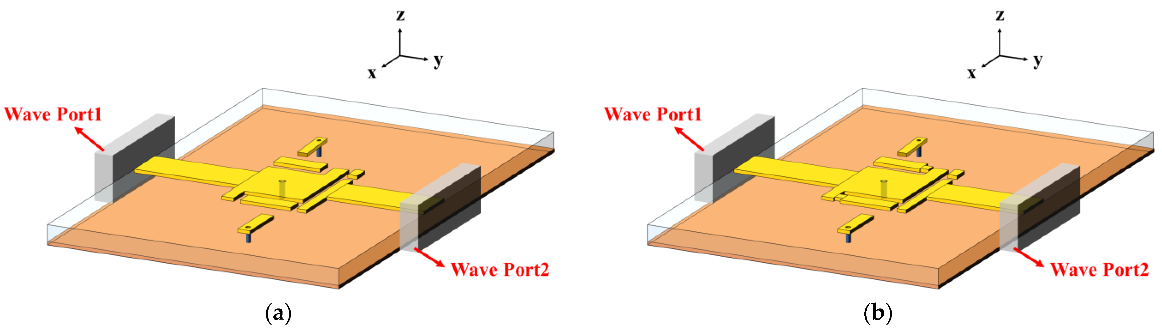
We load PIN diodes at the gap between the main patch and the y-axis parasitic patches. PIN diodes can change the area of the main patch in the x-axis, which is equivalent to changing the value of the capacitance CR. Since PIN diodes do not change the area of the main patch in the y-axis, the value of the inductance LR is unchanged. Therefore, we can tune the ZOR frequency of the MTM antenna by changing the state of the PIN diodes. The antenna cell has two PIN diodes, and . The states of the PIN diodes opening and shorting are represented by numbers 0 and 1, respectively. There are four states, 0-0, 0-1, 1-0, and 1-1. In order to explore the ZOR frequency-tunable range of the antenna cell, we extract the dispersion curve of the antenna cell. Note that states 0-0 and 1-1 are two tunable states, which determines the tunable range of ZOR frequency. Figure 4a,b are the simulation models of the MTM cell from which we can extract the dispersion curve. The MTM cell is in the middle of the model, and the left and right sides of the model are set to 50 Ω wave ports. The MTM cell is connected to the wave port through the microstrip line to simulate the S-parameter matrix of the cell. The relationship between the dispersion curve and the S-parameter matrix is shown as follows [34]:

Figure 4.
Antenna cell extraction parameter simulation model: (a) 0-0 state; (b) 1-1 state.
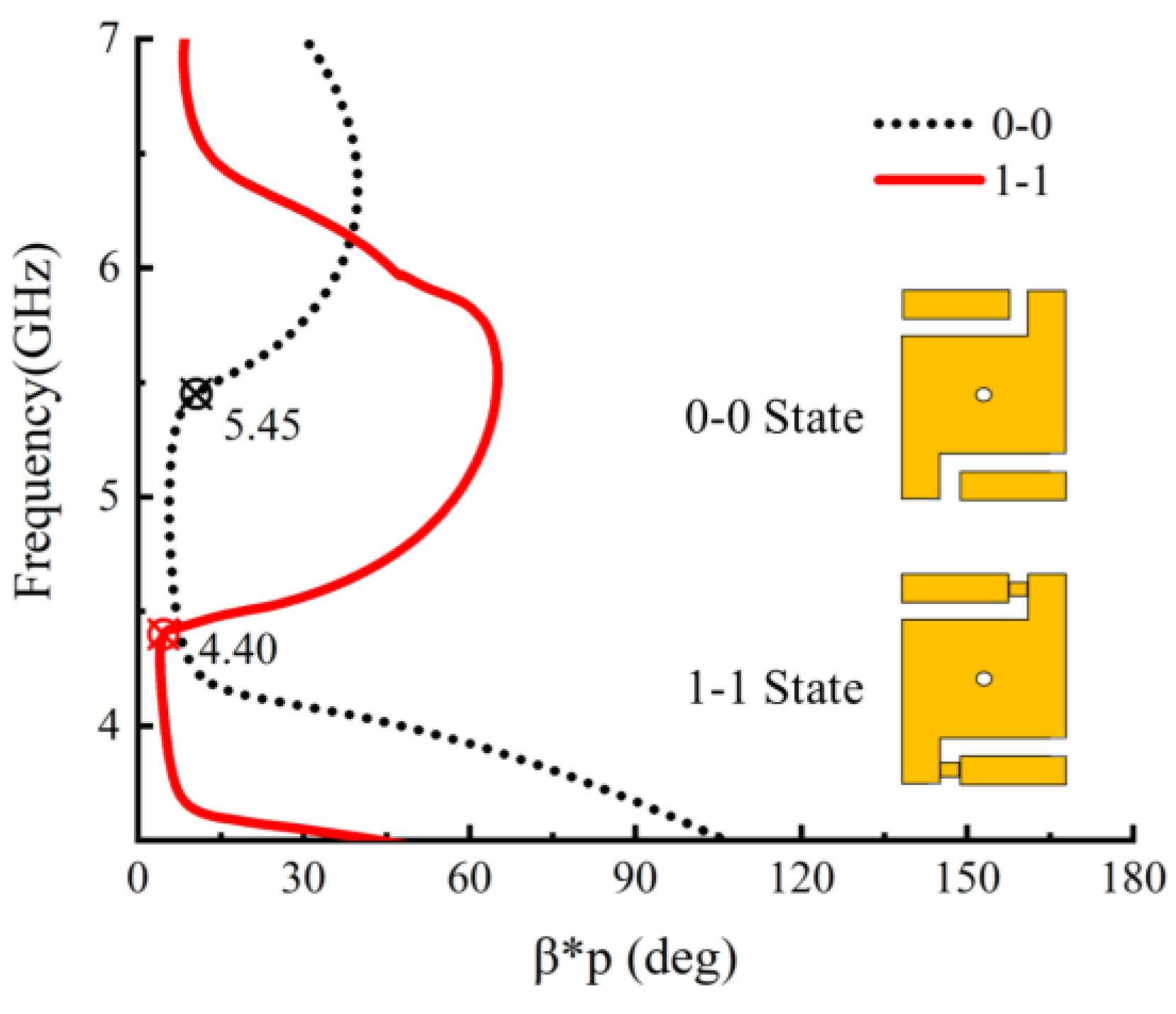
The simulated S-parameter matrix is used to obtain its propagation constant using Equation (2), and the absolute value of its imaginary part is taken to obtain the dispersion curve of the cell, as shown in Figure 5. When the cell is in the 0-0 state, the ZOR frequency is 5.45 GHz, and while the cell is in the 1-1 state, the ZOR frequency is 4.40 GHz. So, the ZOR frequency range for the cell can be tuned between 4.40 GHz and 5.45 GHz.
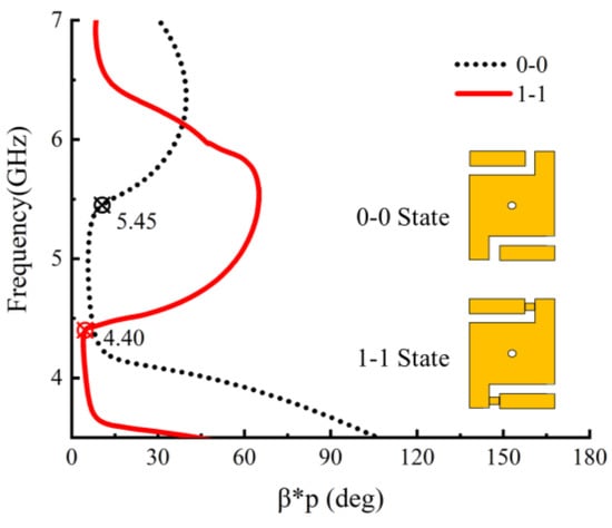
Figure 5.
Cell dispersion curve simulation.
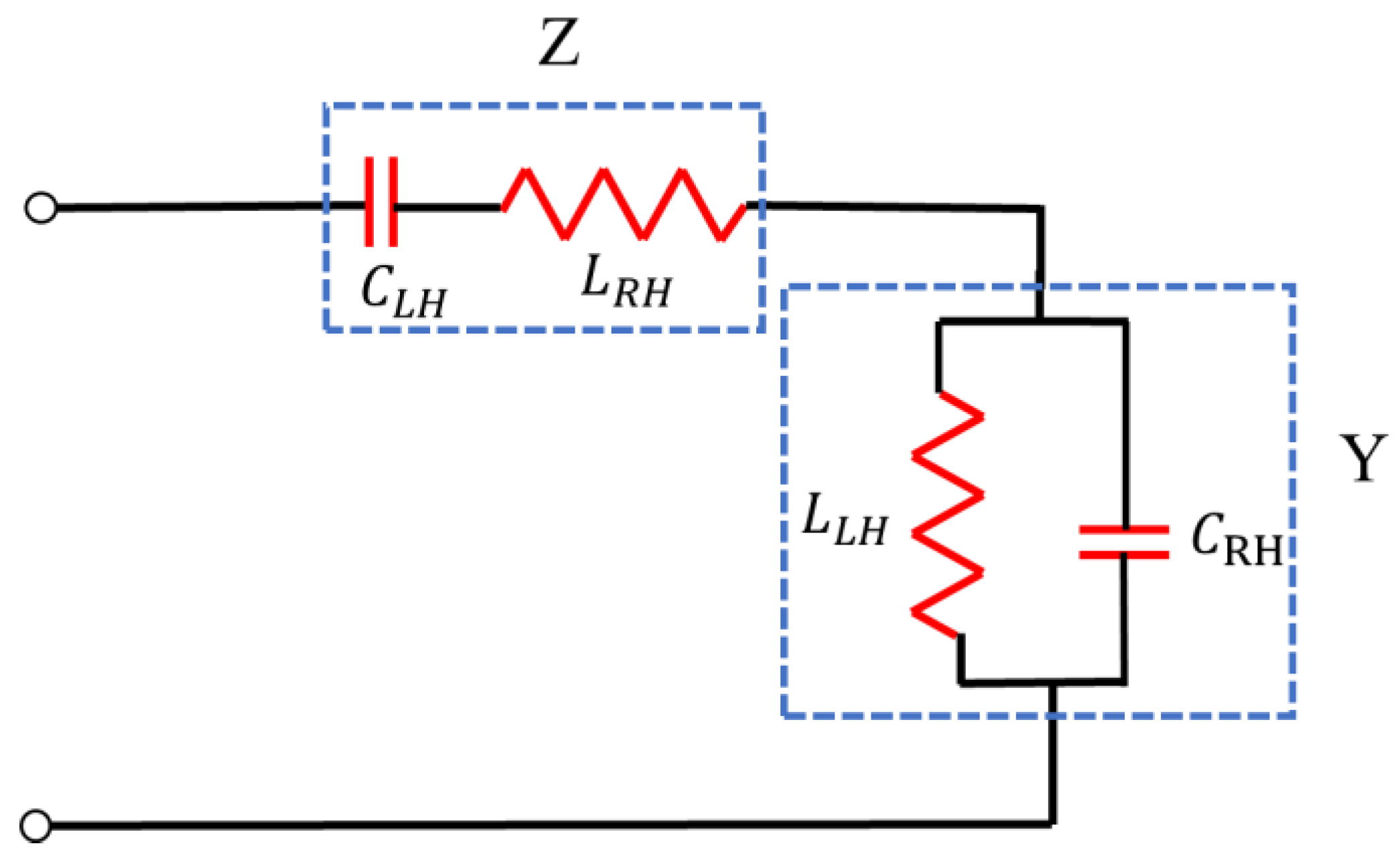
Since the antenna cell is in the form of CRLH-TL, the simplified cell equivalent circuit is shown in Figure 6. CLH, LRH, CRH, and LLH can be solved using the following equations.
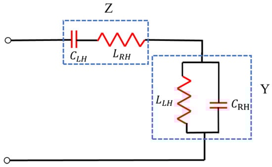
Figure 6.
Equivalent cell circuit model of CRLH-TL.
Here, is the diameter of the through-hole; represents the patch width; represents the patch length; represents the dielectric plate thickness; and represents the distance between the cells. The Bloch–Floquet theory is used to solve the dispersion curve of the transmission line composed of cells with cell length P:
A and D are the transfer matrix coefficients of the equivalent circuit:
Y and Z can be obtained from the equivalent circuit. Substituting the obtained Y and Z into Equations (8)–(10), the analytic dispersion curve of the cell can be obtained.
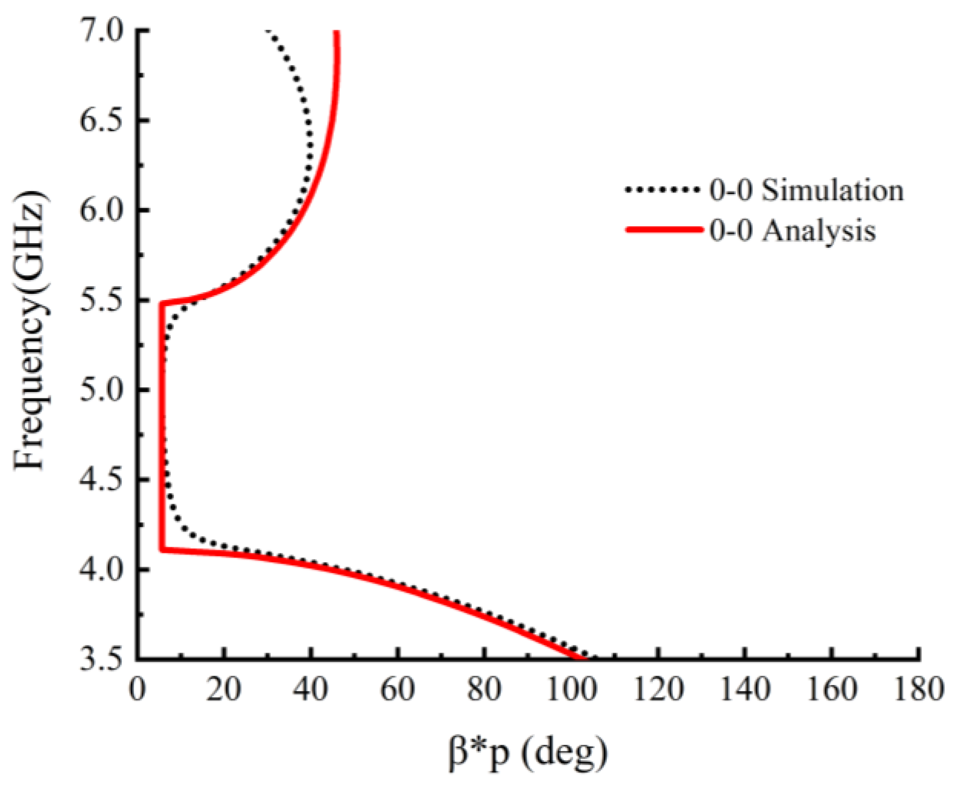
Figure 7 is the comparison of the analytic and simulated dispersion curves when the cell is in the 0-0 state. The simulated ZOR frequency of the dispersion curve is consistent with the analytic ZOR frequency of the dispersion curve, verifying the simulations and the analytical model.

Figure 7.
Comparison of analytic and simulated dispersion curve.
3. Antenna Simulation
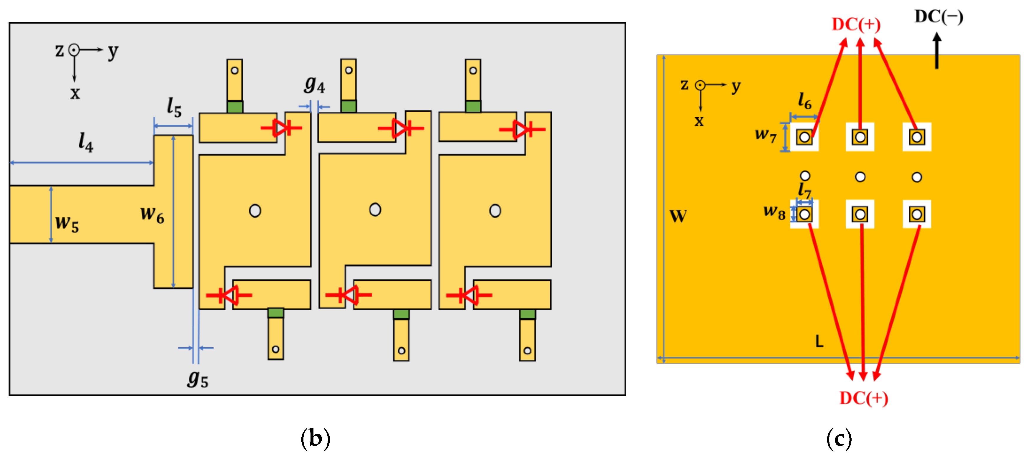
The tunable MTM antenna consists of three periodic MTM cells on the top layer, the dielectric substrate Rogers RO4350 with a thickness of 1.524 mm, and the ground, as shown in Figure 8a. On the top layer, as shown in Figure 8b, the energy goes from the RF signal-fed microstrip line to the three MTM cells, where the coupling and resonance occurs. As shown in Figure 8c, the bottom layer is RF ground, and DC bias lines are connected there. In order to facilitate the design of the DC bias circuit, the bottom layer is connected to the top layer by vias, which are separated from the antenna ground by a small gap, so that both poles of the DC can be fed from the bottom of the antenna, and the bias circuit patch in the x-axis only needs one. DC bias lines are located on the antenna ground rather than on the top layer of the antenna, thereby reducing the influence of DC bias lines on the radiation performance of the antenna. Table 2 provides the size of the antenna.
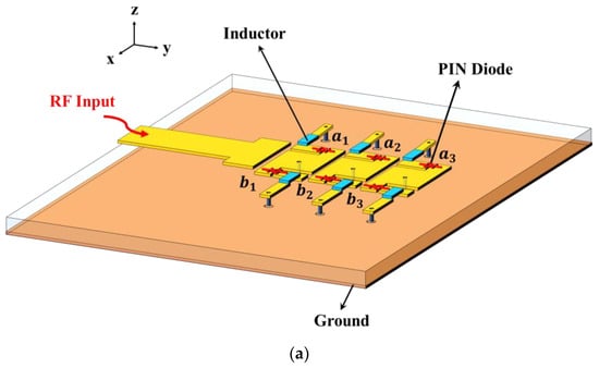
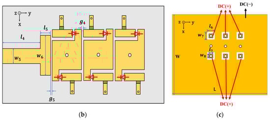
Figure 8.
Antenna structure and DC bias circuit design: (a) 3D model; (b) top view; (c) bottom view.
Table 2.
Dimensions of the proposed antenna (mm).
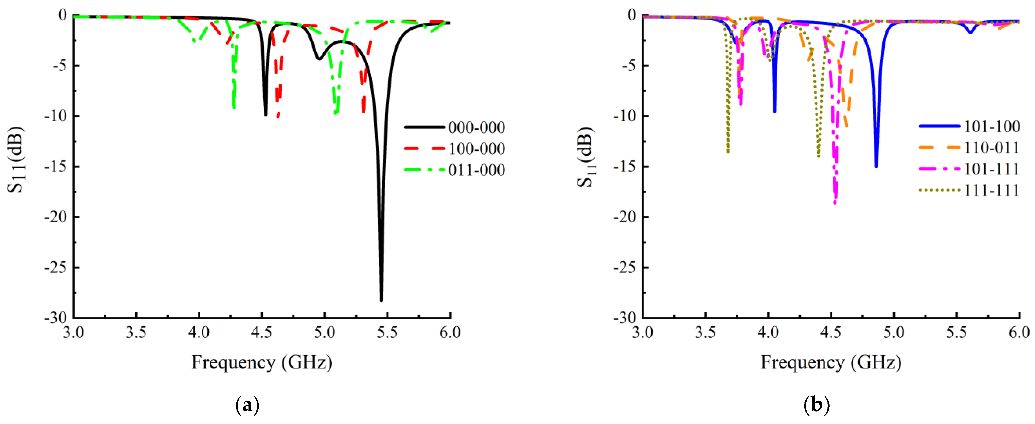
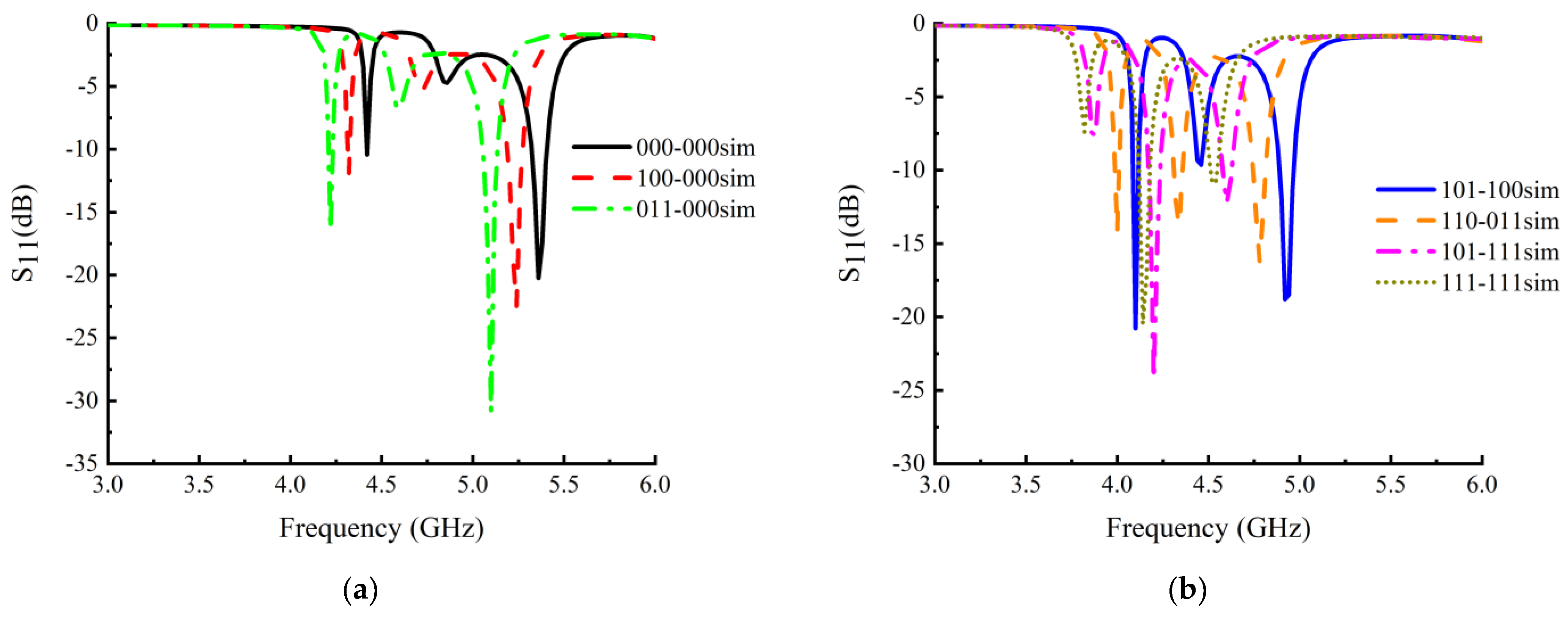
In terms of the specifical design, the antenna has six PIN diodes, as shown in Figure 8a, and its state changes from 000-000 to 111-111. Hence, the antenna theoretically has 43 = 64 coding states. Because the main structure of the antenna is centrosymmetric, there are 28 kinds of overlapping states, resulting in 36 effective coding states. Figure 9 presents the simulation results of the S-parameters for the MTM antenna with seven coding states: 000-000, 100-000, 011-000, 101-100, 110-011, 101-111, and 111-111. It is noteworthy that the ZOR frequency of the two terminal states, 000-000 and 111-111, are precisely 5.45 GHz and 4.40 GHz, respectively. The frequency aligns perfectly with the ZOR frequency of the antenna cell’s two states, 0-0 and 1-1. Meanwhile, it is completely consistent with the ZOR theory [40,41]: the ZOR frequency is independent of the number of cells, which determines the overall physical size of the antenna, so the ZOR frequency of the MTM antenna is independent of the overall physical size of the antenna. Although the ZOR frequency is independent of the number of cells, the number of resonance modes of the antenna is determined by the number of cells. The proposed antenna has three cells, so there will be three resonance modes (including ZOR). The bandwidth of the antenna at the ZOR frequency is less than 0.1 GHz, indicating that the antenna has good narrowband characteristics and has the potential to be applied to the 5G NB-IoT in the future.
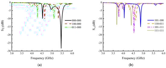
Figure 9.
S-parameter simulation results of different coding states: (a) 000-000, 100-000, 011-000; (b) 101-100, 110-011, 101-111, 111-111.
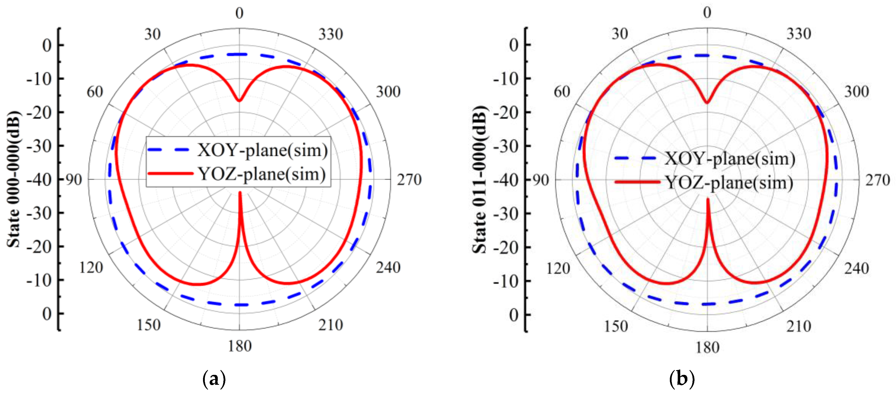
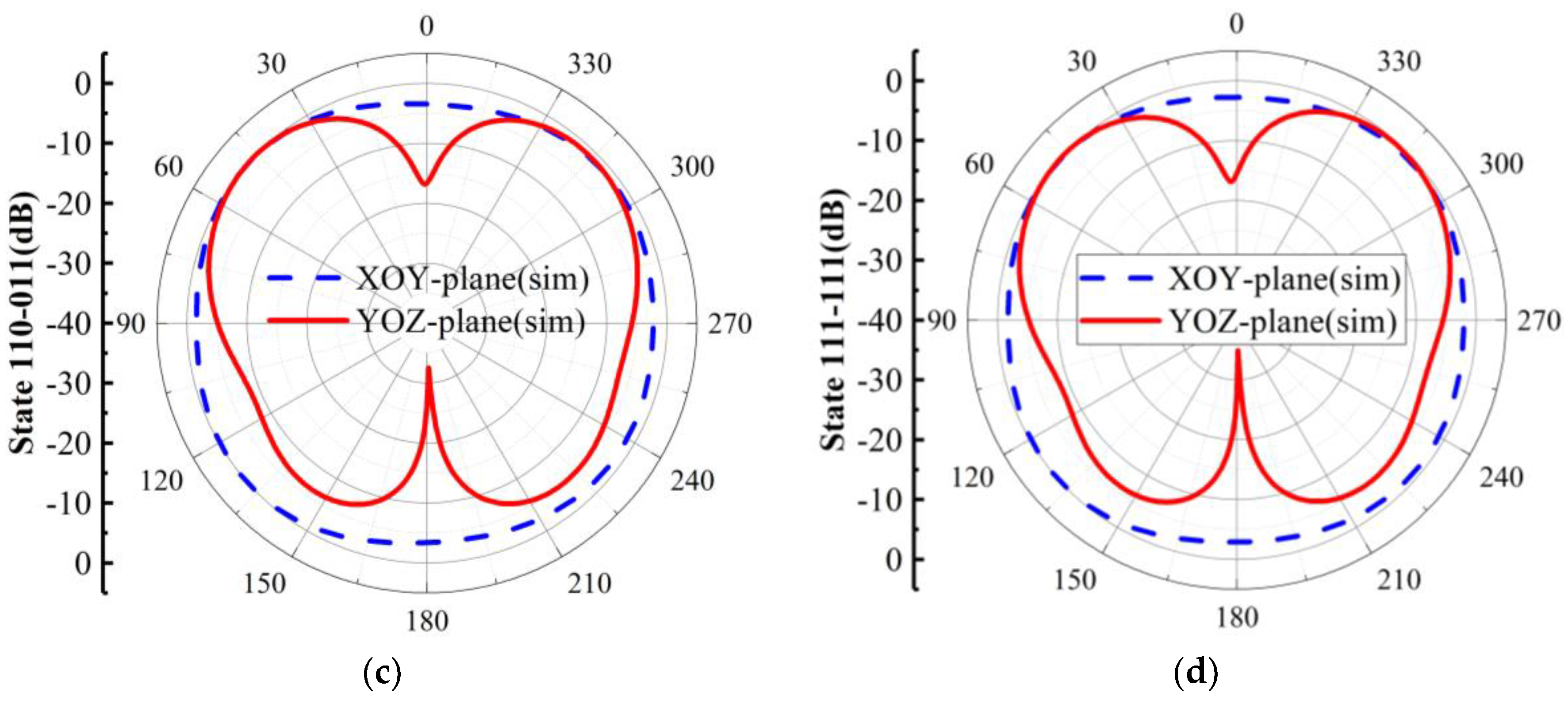
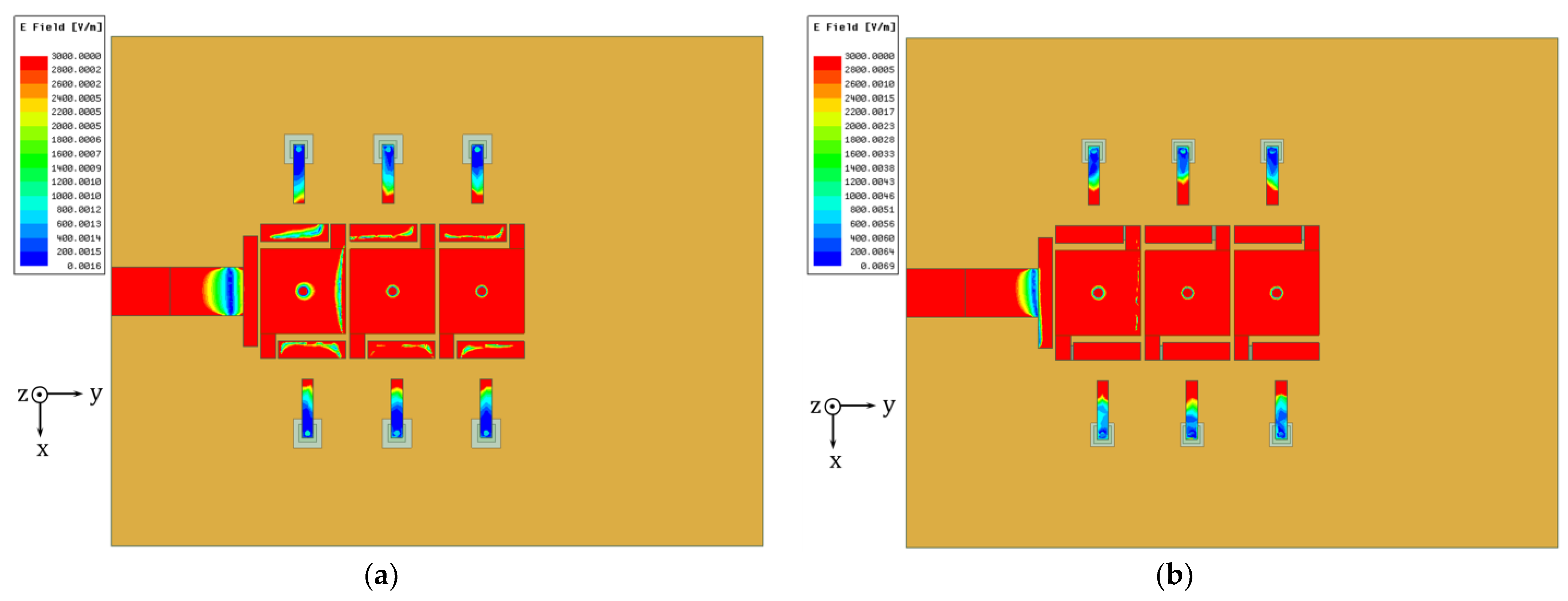
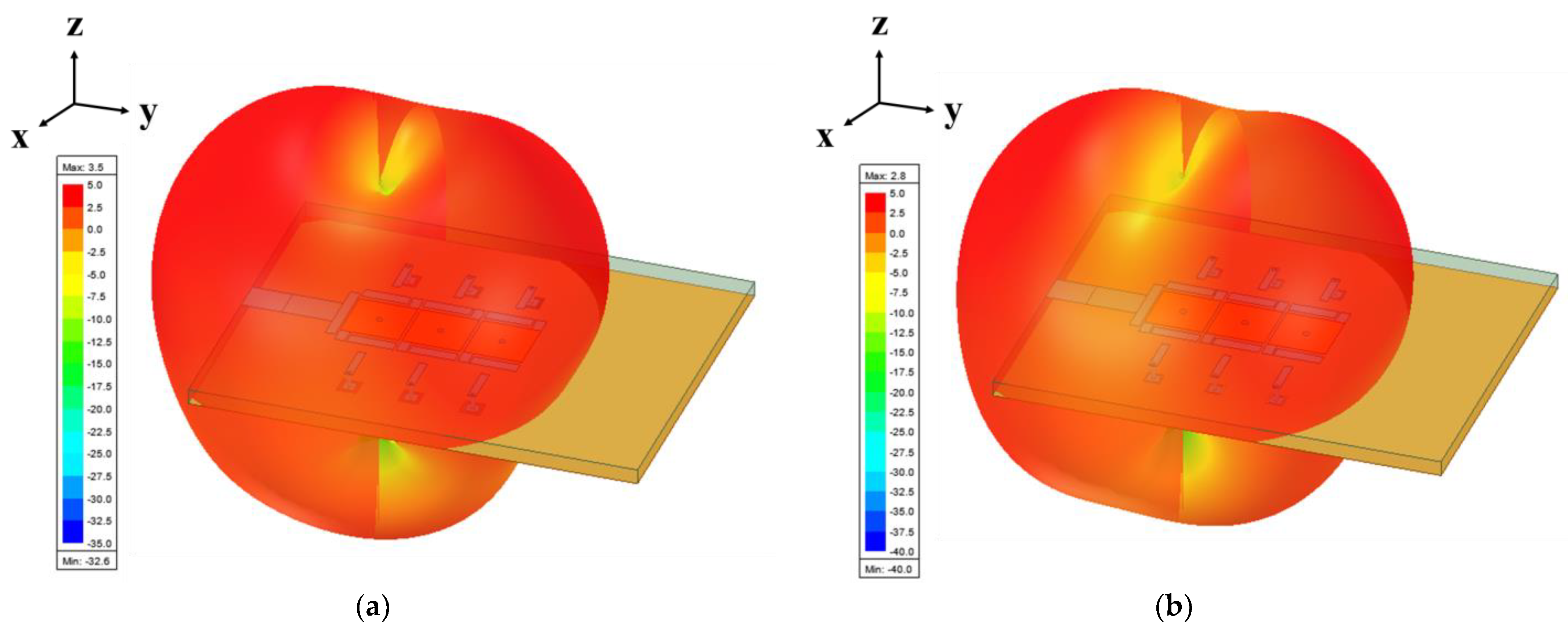
We simulate the radiation patterns of the xoy plane and the yoz plane of the antenna in the states of 000-000, 011-000, 110-011, and 111-111, as shown in Figure 10. Since the antenna is operating in ZOR state, radiation patterns in the two terminal states are basically the same and do not change too much. Hence, radiation patterns of other states between the two terminal states will be basically the same as well. Compared with [34], the MTM antenna solves the problem of radiation patterns changing in different states. Although the state of the active device changes at different operating frequencies, the antenna radiation pattern basically does not change. We simulate the electric field at ZOR when the antenna is in the states of 000-000 and 111-111, as shown in Figure 11. When the antenna is in the ZOR state, the electric field intensity of each cell is almost the same along the y-axis, indicating that most of the energy is concentrated on the main structure of the antenna, and the electrical field is distributed uniformly along the three cells, verifying the ZOR features [40,41]. We also simulate the 3D far-field radiation patterns of the antenna in the states of 000-000 and 111-111, as shown in Figure 12. The 3D far-field radiation patterns in the two states are basically the same.
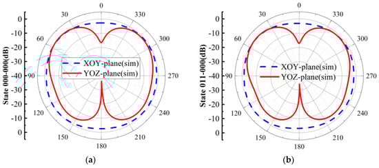
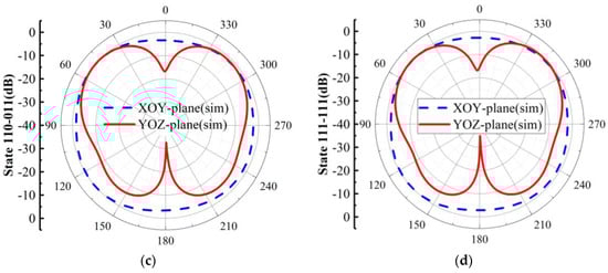
Figure 10.
Radiation patterns of the antenna in different states: (a) 000-000; (b) 011-000; (c) 110-011; (d) 111-111.
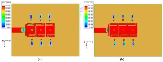
Figure 11.
Electric field of the antenna in different states: (a) 000-000; (b) 111-111.
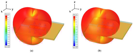
Figure 12.
Three-dimensional far-field radiation patterns of the antenna in different states: (a) 000-000; (b) 111-111.
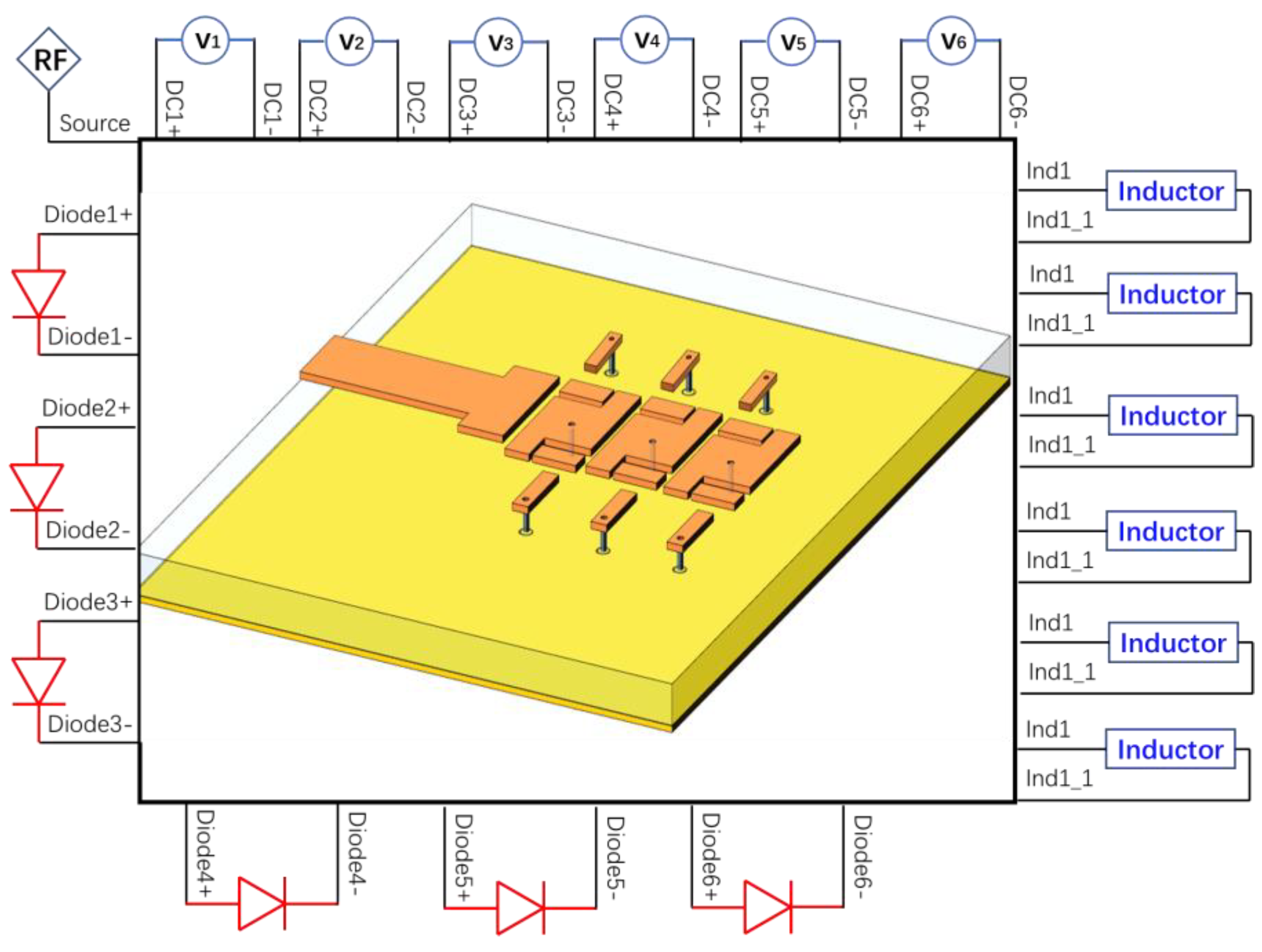
In order to further study the characteristics of the active MTM antenna, we integrate HFSS-based full-wave simulation with circuit simulation, enabling field-circuit co-simulation. The MTM antenna, isolation inductors, bias circuits of the active device, and PIN diodes are all considered for active simulation, as shown in Figure 13. The specific process of field-circuit co-simulation is as follows: First, the lumped port is set at the position where the device and the bias voltage are loaded on the metamaterial antenna, and then the model is simulated in HFSS. Second, the simulated metamaterial antenna model is imported into the circuit simulation software. At this time, the model of the metamaterial antenna is a multi-ports model, which contains the S-parameter information simulated in the HFSS field. Then, the S2P file of the inductor and the S2P model of the PIN diode are imported into the circuit, and the DC voltage source is found in the component library provided by the circuit software. The metamaterial antenna model relates to each device model and voltage source model. Finally, the S-parameters of the model are simulated. The PIN diode model is MACOM MA4AGFCP910, the inductor model is Murata LQW18AN22NG00, and the isolation () is less than −20 dB. The field-circuit co-simulation results of the active MTM antenna, based on PIN diodes, are shown in Figure 14. The ZOR covers the frequency range of 4.52–5.36 GHz. All states have good impedance matching, and the bandwidth of a single ZOR range is 0.04–0.07 GHz, indicating it has good narrowband characteristics. In order to facilitate the clear display of the S-parameter, only seven states are shown in Figure 14.
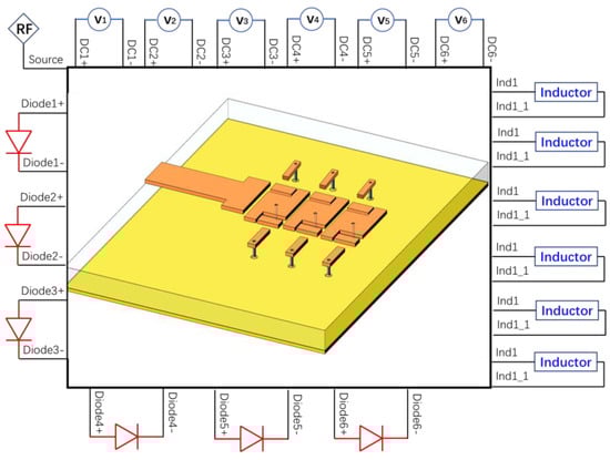
Figure 13.
Field-circuit co-simulation.
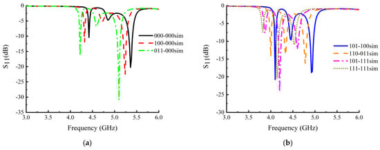
Figure 14.
S-parameter simulation results of field-circuit co-simulation with different coding states: (a) 000-000, 100-000, 011-000; (b) 101-100, 110-011, 101-111, 111-111.
4. Antenna Measurement
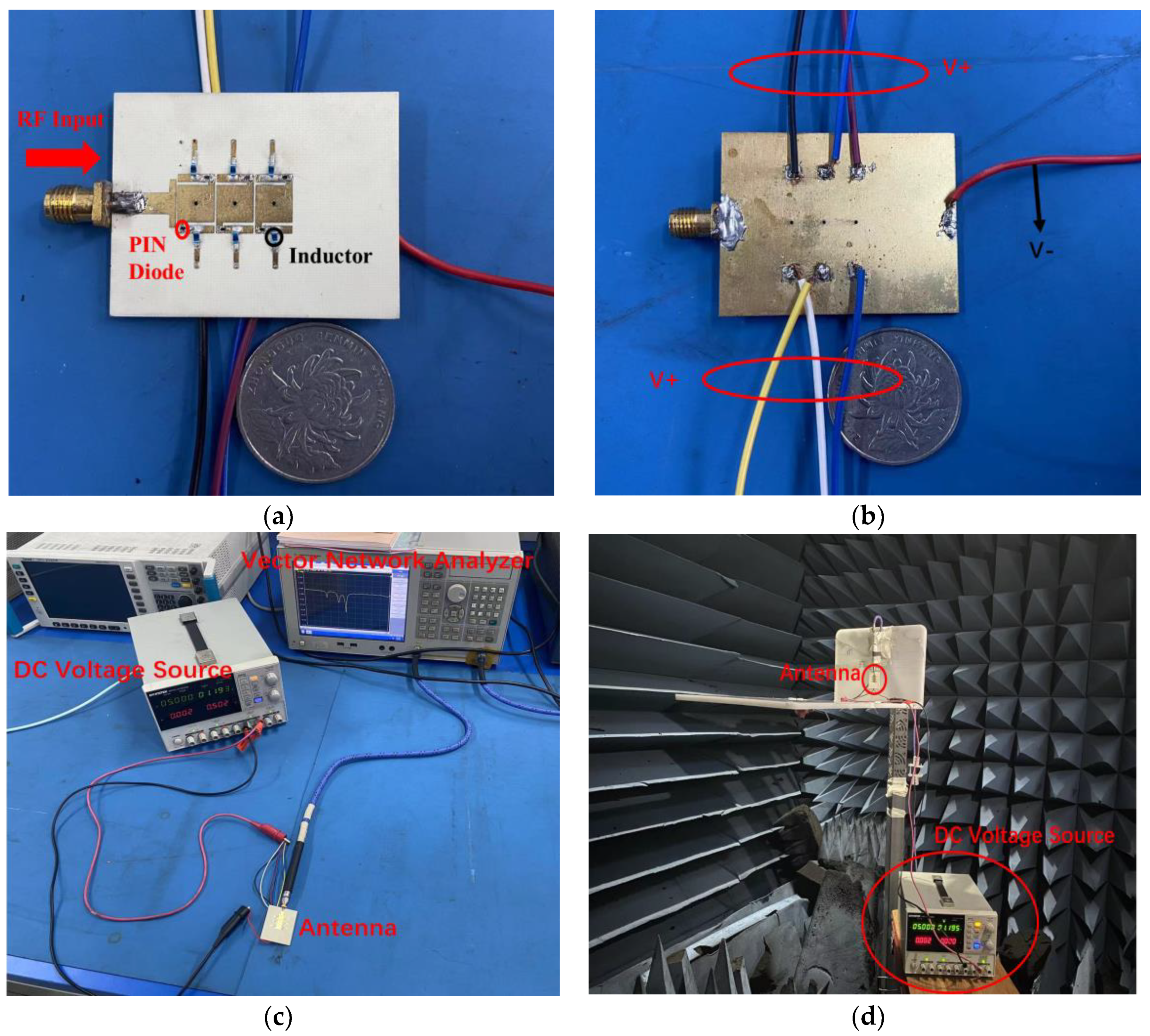
According to the antenna simulation model in Section 3, the fabricated active MTM antenna is shown in Figure 15a,b. The MTM antenna is fabricated on the Rogers RO4350 with the thickness 1.524 mm. The top layer of the active MTM antenna is shown in Figure 15a. There are three period cells, and the cell size is 5.8 mm. Each antenna cell employs two PIN diodes as active devices and two inductors to block the RF signal. Figure 15b displays the bottom layer of the MTM antenna, in which the bias line is connected to the voltage source to control the state of the PIN diode on the MTM antenna, so as to realize the tunable characteristics. In the design of the metamaterial antenna, the metamaterial cells are fed by coupling. The gap between the cells is the same as the DC blocking capacitor, which can prevent the DC voltage from being directly loaded into the Vector Network Analyzer (VNA). The tunable characteristics are measured via the VNA, as shown in Figure 15c. For the designed active MTM antenna, the far-field test system and environment are shown in Figure 15d. A tray is installed on the bracket of the turntable of the microwave anechoic chamber to fix the active metamaterial antenna on the tray. The SMA joint on the active metamaterial antenna is connected to the VNA in the darkroom through the DuPont line to input the RF signal. At the same time, the voltage source is used to control the state of the PIN diode to realize the control of the overall state of the antenna. The microwave anechoic chamber system can measure a series of far-field parameters of the antenna, such as pattern and gain. After completing the corresponding parameter test, the system processes the test data and outputs them in the form of a table to facilitate our subsequent data processing.

Figure 15.
Fabricated antenna includes: (a) top view; (b) bottom view; (c) S-parameter measurement; (d) anechoic chamber measurements.
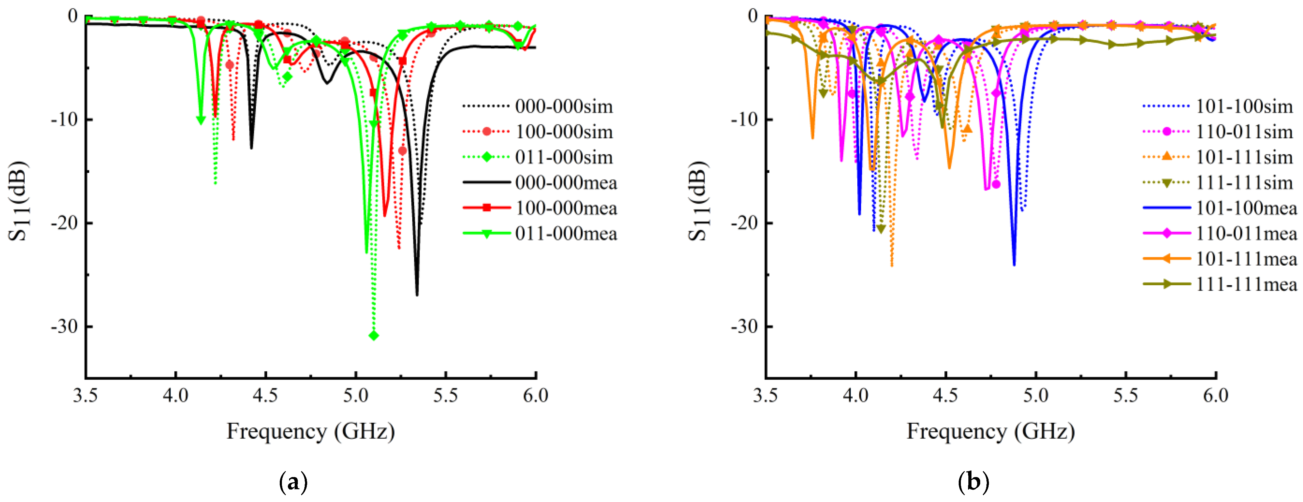
We select seven different states that are the same as the field-circuit co-simulation to measure the S-parameters and compare the measured results with the field-circuit co-simulated results, as shown in Figure 16. The ZOR frequency range of the co-simulation is 4.52–5.36 GHz, and the measured ZOR frequency range is 4.48–5.34 GHz. The simulation and measurement bandwidth of a single ZOR is 0.05–0.09 GHz. The antenna has good narrowband characteristics at the ZOR frequency. The measured S-parameters align well with the simulated results.
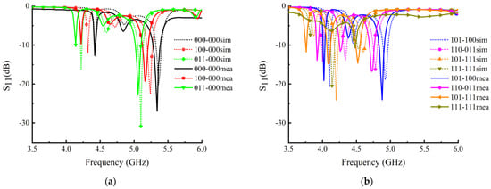
Figure 16.
Comparison of S-parameters between field-circuit co-simulation and measurement of the antenna in different coding states: (a) 000-000, 100-000, 011-000; (b) 101-100, 110-011, 101-111, 111-111.
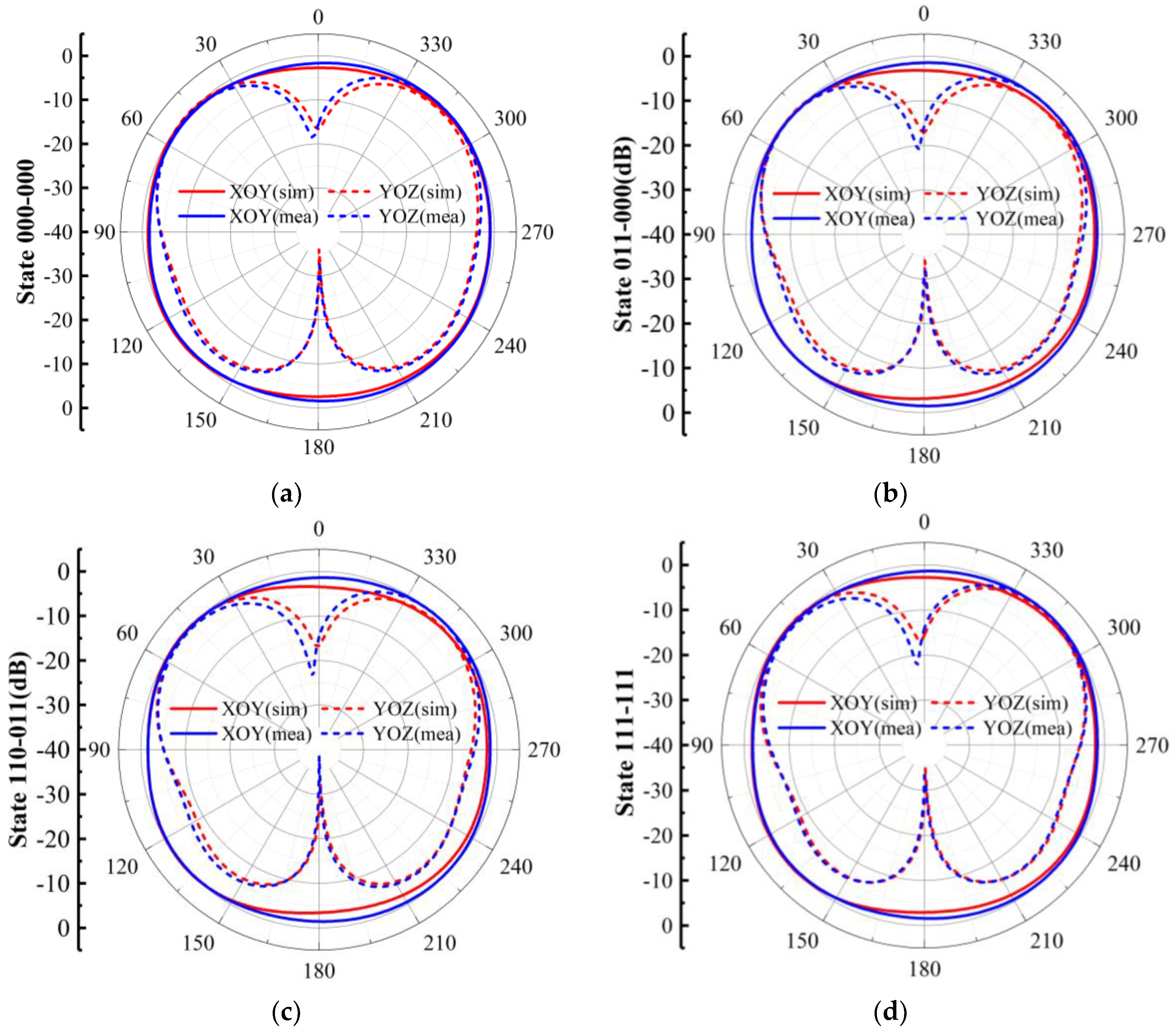
As shown in Figure 17, the multi-states radiation pattern of the designed active MTM antenna is similar and it is close to the simulation results, indicating that the radiation performance of the active MTM antenna is basically not affected by the active device and the bias circuit. The gain range of the antenna in different coding states is 2.45–3.46 dBi.
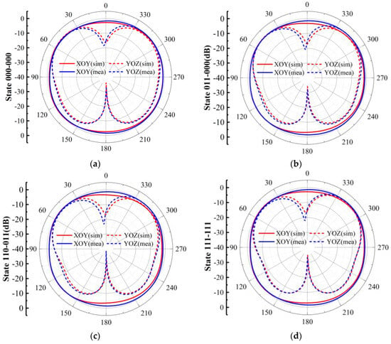
Figure 17.
Pattern measurement of the antenna in different states: (a) 000-000; (b) 011-000; (c) 110-011; (d) 111-111.
Table 3 shows the comparison between the designed antenna and other works. Refs. [16,19,21] all utilize varactors to achieve multiple ZOR frequency tuning. However, the varactor requires high-bias voltages even as high as 20 V, and the power consumption is large. In [23,24], PIN diodes are used to achieve ZOR frequency tuning. The PIN diode requires low-bias voltages around 1.5 V, but these relative works usually obtain a few tunable ZORs, which limits their application scenarios. The work in Ref. [42] has the same application scenario as that in our work. However, this paper has many improvements compared with [42]. First, concerning the design, the proposed antenna cell in our work is a mushroom-shaped structure, and the antenna cell in [42] is a “J”-shaped structure. Second, with the completely different cell design from the antenna cell structure in [42], the dispersion curve is totally different, which leads to advantages in the performance. The ZOR tunable range of our antenna is 4.4 GHz–5.45 GHz, while that in [42] is 4.7 GHz–5.3 GHz, meaning that the proposed tunable ZOR is 0.45 GHz larger than that of [42]. In other words, the ZOR tunable range of our antenna is 75% larger than that of [42]. Third, comparing with other relative works, the proposed antenna has 36 tunable ZORs, and the bias voltage requires only 0–1.2 V. Moreover, our antenna has good narrowband characteristics, which has good potential to be applied to 5G NB-IoT.
Table 3.
Comparison of other references’ works.
5. Conclusions
In this paper, a ZOR tunable MTM antenna is proposed and experimentally verified. The ZOR frequency of the MTM antenna is tunable by loading PIN diodes, and the dispersion curve of the antenna cell is extracted to verify the ZOR state. The experimental results show that the antenna has 36 tunable ZOR states. The ZOR frequency-tunable range of the antenna is 4.48–5.34 GHz, and the bandwidth of a single ZOR is 0.05–0.09 GHz, which has good narrowband characteristics. The radiation patterns of different ZORs are basically the same without distortion. The proposed tunable and narrowband MTM antenna can be applied to the 5G NB-IoT scenarios.
Author Contributions
Conceptualization, L.Y. and Y.L.; validation, Z.L. and Y.L.; writing—original draft preparation, Z.L.; writing—review and editing, H.L. and Y.L.; project administration, Y.L. All authors have read and agreed to the published version of the manuscript.
Funding
This research received no external funding.
Data Availability Statement
The data presented in this study are openly available.
Conflicts of Interest
The authors declare no conflict of interest.
References
- Veselago, V.G. The electrodynamics of substances with simultaneously negative values of ε and μ. Sov. Phys. Usp. 1968, 10, 509–514. [Google Scholar] [CrossRef]
- Eleftheriades, G.V.; Balmain, K.G. Negative-Refraction Metamaterials: Fundamental Principles and Applications. Mater. Today 2005, 8, 440. [Google Scholar]
- Engheta, N.; Mickelson, A.; Papas, C. On the Near-Zone Inverse Doppler Effect. IEEE Trans. Antennas Propag. 1980, 28, 519–522. [Google Scholar] [CrossRef]
- Lai, A.; Itoh, T.; Caloz, C. Composite right/left-handed transmission line metamaterials. IEEE Microw. Mag. 2004, 5, 34–50. [Google Scholar] [CrossRef]
- Caloz, C.; Itoh, T. Array factor approach of leaky-wave antennas and application to 1-D/2-D composite right/left-handed(CRLH) structures. IEEE Microw. Wirel. Compon. Lett. 2004, 14, 274–276. [Google Scholar] [CrossRef]
- Costa, F.; Monorchio, A.; Manara, G. Analysis and Design of Ultra Thin Electromagnetic Absorbers Comprising Resistively Loaded High Impedance Surfaces. IEEE Trans. Antennas Propag. 2010, 58, 1551–1558. [Google Scholar] [CrossRef]
- Costa, F.; Monorchio, A. A Frequency Selective Radome with Wideband Absorbing Properties. IEEE Trans. Antennas Propag. 2012, 60, 2740–2747. [Google Scholar] [CrossRef]
- Saraband, K.; Behdad, N. A Frequency Selective Surface with Miniaturized Elements. IEEE Trans. Antennas Propag. 2007, 55, 1239–1245. [Google Scholar] [CrossRef]
- Kern, D.J.; Werner, D.H.; Monorchio, A. The Design Synthesis of Multiband Artificial Magnetic Conductors Using High Impedance Frequency Selective Surfaces. IEEE Trans. Antennas Propag. 2005, 53, 8–17. [Google Scholar] [CrossRef]
- Shu, J.; Zhang, Y.; Zheng, Z. A Novel Beam Steerable Antenna Employing Tunable High Impedance Surface with Liquid Crystal. IEEE Access 2020, 8, 118687–118695. [Google Scholar] [CrossRef]
- Yin, J.Y.; Ren, J.; Zhang, Q. Frequency-Controlled Broad-Angle Beam Scanning of Patch Array Fed by Spoof Surface Plasmon Polaritons. IEEE Trans. Antennas Propag. 2016, 64, 5181–5189. [Google Scholar] [CrossRef]
- Guan, D.F.; Peng, Y.; Zhang, Q. Hybrid Spoof Surface Plasmon Polariton and Substrate Integrated Waveguide Transmission Line and Its Application in Filter. IEEE Trans. Microw. Theory Tech. 2017, 65, 4925–4932. [Google Scholar] [CrossRef]
- Kang, H.; Lim, S. Electrically small dual-band reconfigurablecomplementary split-ring resonator (CSRR)-loaded eighth-mode substrate tntegrated waveguide (EMSIW) antenna. IEEE Trans. Antennas Propag. 2014, 62, 2368–2373. [Google Scholar] [CrossRef]
- Somarith, S.; Hyunseong, K.; Sungjoon, L. Frequency reconfigurable and miniaturized substrate integrated waveguide interdigital capacitor (SIW-IDC) antenna. IEEE Trans. Antennas Propag. 2014, 62, 1039–1045. [Google Scholar] [CrossRef]
- Cui, T.J.; Qi, M.Q.; Wan, X.; Zhao, J.; Cheng, Q. Coding metamaterials, digital metamaterials and programmable metamaterials. Light. Sci. Appl. 2014, 3, 27–35. [Google Scholar] [CrossRef]
- Cui, T.J. Microwave metamaterials—From passive to digital and programmable controls of electromagnetic waves. J. Opt. 2017, 19, 4004–4038. [Google Scholar] [CrossRef]
- Jackson, D.R.; Caloz, C.; Itoh, T. Leaky-wave antennas. Proc. IEEE 2012, 100, 2194–2206. [Google Scholar] [CrossRef]
- Chen, S.L.; Karmokar, D.K.; Li, Z.; Qin, P.Y.; Ziolkowski, R.W.; Guo, Y. Continuous Beam Scanning at a Fixed Frequency with a Composite Right-/Left-Handed Leaky-Wave Antenna Operating Over a Wide Frequency Band. IEEE Trans. Antennas Propag. 2019, 67, 7272–7284. [Google Scholar] [CrossRef]
- Fu, J.-H.; Li, A.; Chen, W.; Lv, B.; Wang, Z.; Li, P.; Wu, Q. An Electrically Controlled CRLH-Inspired Circularly Polarized Leaky-Wave Antenna. IEEE Antennas Wirel. Propag. Lett. 2017, 16, 760–763. [Google Scholar] [CrossRef]
- Meng, W.; Hui, F.M.; Hao, C.Z.; Tang, W.; Zhang, X.; Cui, T. Frequency-Fixed Beam-Scanning Leaky-Wave Antenna Using Electronically Controllable Corrugated Microstrip Line. IEEE Trans. Antennas Propag. 2018, 66, 4449–4457. [Google Scholar]
- Chen, K.; Zhang, Y.; He, S.Y.; Chen, H.T.; Zhu, G.Q. An Electronically Controlled Leaky-Wave Antenna Based on Corrugated SIW Structure with Fixed-Frequency Beam Scanning. IEEE Antennas Wirel. Propag. Lett. 2019, 18, 551–555. [Google Scholar] [CrossRef]
- Shaw, R.; Mandal, M.K. Broadside Scanning Fixed Frequency LWA with Simultaneous Electronic Control of Beam angle and Beamwidth. IEEE Trans. Antennas Propag. 2020, 58, 3504–3514. [Google Scholar] [CrossRef]
- Liu, P.; Jiang, W.; Sun, S.; Xi, Y.; Gong, S. Broadband and Low-Profile Penta-Polarization Reconfigurable Metamaterial Antenna. IEEE Access 2020, 8, 21823–21831. [Google Scholar] [CrossRef]
- Feng, B.; Li, L.; Zeng, Q.; Sim, C.-Y. A Low-Profile Metamaterial Loaded Antenna Array with Anti-Interference and Polarization Reconfigurable Characteristics. IEEE Access 2018, 6, 35578–35589. [Google Scholar] [CrossRef]
- Jang, Y.; Choi, J.; Lim, S. Frequency tunable zeroth-order resonant antenna by using RF MEMS on slotted ground plane. In Proceedings of the 2010 Asia-Pacific Microwave Conference, Yokohama, Japan, 7–10 December 2010. [Google Scholar]
- Kim, J.; Kim, G.; Seong, W.; Choi, J. A Tunable Internal Antenna with an Epsilon Negative Zeroth Order Resonator for DVB-H Service. IEEE Trans. Antennas Propag. 2009, 57, 4014–4017. [Google Scholar]
- Mirzaei, H.; Eleftheriades, G.V. A Compact Frequency-Reconfigurable Metamaterial-Inspired Antenna. IEEE Antennas Wirel. Propag. Lett. 2011, 10, 1154–1157. [Google Scholar] [CrossRef]
- Boukarkar, A.; Lin, X.Q.; Jiang, Y. A Dual-Band Frequency-Tunable Magnetic Dipole Antenna for WiMAX/WLAN Applications. IEEE Antennas Wirel. Propag. Lett. 2015, 15, 492–495. [Google Scholar] [CrossRef]
- Yu, Y.; Xiong, J.; Li, H.; He, S. An Electrically Small Frequency Reconfigurable Antenna with a Wide Tuning Range. IEEE Antennas Wirel. Propag. Lett. 2011, 10, 103–106. [Google Scholar]
- Huang, H.-J.; Tsai, C.-H.; Lai, C.-P.; Chen, S.-Y. Frequency-Tunable Miniaturized Strip Loop Antenna Fed by a Coplanar Strip. IEEE Antennas Wirel. Propag. Lett. 2016, 15, 1000–1003. [Google Scholar] [CrossRef]
- Chi, P.-L.; Waterhouse, R.; Itoh, T. Compact and Tunable Slot-Loop Antenna. IEEE Trans. Antennas Propag. 2011, 59, 1394–1397. [Google Scholar] [CrossRef]
- Ko, J.; Kim, D. A Wideband Frequency-Tunable Dipole Antenna Based on Antiresonance Characteristics. IEEE Antenna Wirel. Propag. Lett. 2017, 16, 3067–3070. [Google Scholar] [CrossRef]
- Takemura, N. Tunable Inverted-L Antenna with Split-Ring Resonator Structure for Mobile Phones. IEEE Trans. Antennas Propag. 2012, 61, 1891–1897. [Google Scholar] [CrossRef]
- Choi, J.; Lim, S. Frequency and Radiation Pattern Reconfigurable Small Metamaterial Antenna using its Extraordinary Zeroth-Order Resonance. J. Electromagn. Waves Appl. 2010, 24, 2119–2127. [Google Scholar] [CrossRef]
- Khan, M.S.; Capobianco, A.D.; Iftikhar, A.; Asif, S.; Ijaz, B.; Braaten, B.D. A Frequency-Reconfigurable Series-Fed Microstrip Patch Array with Interconnecting CRLH Transmission Lines. IEEE Antennas Wirel. Propag. Lett. 2016, 15, 242–245. [Google Scholar] [CrossRef]
- Chen, M.; Miao, Y.; Hao, Y.; Hwang, K. Narrow band internet of things. IEEE Access 2017, 5, 20557–20577. [Google Scholar] [CrossRef]
- Ma, H.; Qi, J.; Li, K.; He, C. Plant growth monitoring cloud platform based on internet of things. In Proceedings of the 2021 6th International Conference on Intelligent Computing and Signal Processing (ICSP), Xi’an, China, 9–11 April 2021. [Google Scholar]
- Shi, J.; Jin, L.; Li, J.; Fang, Z. A smart parking system based on NB-IoT and third-party payment platform. In Proceedings of the 2017 17th International Symposium on Communications and Information Technologies (ISCIT), Cairns, Australia, 25–27 September 2021. [Google Scholar]
- Cao, X.; Li, Y. Data collection and network architecture analysis in internet of vehicles based on NB-IoT. In Proceedings of the 2018 International Conference on Intelligent Transportation, Big Data & Smart City (ICITBS), Xiamen, China, 25–26 January 2018. [Google Scholar]
- Lee, S.W.; Lee, J.H. Electrically Small MNG ZOR Antenna with Multilayered Conductor. IEEE Antennas Wirel. Propag. Lett. 2010, 9, 724–727. [Google Scholar] [CrossRef]
- Yan, S.; Vandenbosch, G. Zeroth-order resonant circular patch antenna based on periodic structures. IET Microw. Antennas Propag. 2014, 8, 1432–1439. [Google Scholar] [CrossRef]
- Luo, Y.; Liu, H.; He, Y.; Cui, H.; Yang, G. Continuous Resonance Tuning without Blindness by Applying Nonlinear Properties of PIN Diodes. Sensors 2021, 21, 2816. [Google Scholar] [CrossRef]


Disclaimer/Publisher’s Note: The statements, opinions and data contained in all publications are solely those of the individual author(s) and contributor(s) and not of MDPI and/or the editor(s). MDPI and/or the editor(s) disclaim responsibility for any injury to people or property resulting from any ideas, methods, instructions or products referred to in the content. |
© 2023 by the authors. Licensee MDPI, Basel, Switzerland. This article is an open access article distributed under the terms and conditions of the Creative Commons Attribution (CC BY) license (https://creativecommons.org/licenses/by/4.0/).