1. Introduction
In semiconductor manufacturing, since the early 1990s,
computer-integrated manufacturing (CIM) systems have been helping foundries to gain better production efficiency and wafer quality with various control software systems and sensors [
1]. With CIM, a lot of tasks, such as uploading and changing recipes on semiconductor tools, can be performed automatically instead of manually controlled by engineers. This greatly releases engineers from complex and generous routine work. Additionally, it can avoid wafer quality problems and semiconductor tool failures caused by manually improper operations on semiconductor tools.
CIM was first released in the early 1970s by Dr. Joseph Harrington [
2]. It is a manufacturing philosophy that uses computers to control an entire production process. Then, different operations can be well synchronized such that the cycle time for a process becomes much shorter. Additionally, CIM makes the manufacturing process less error-prone. To the best knowledge of the authors of this work, most of the semiconductor fabs install relevant software systems to support CIM [
3], such as
manufacture execution system (MES) [
4,
5,
6],
material control system (MCS),
automation material handling system (AMHS),
recipe management system (RMS), and EAP.
MES is the core part of CIM and helps engineers manage and control the manufacturing environment and procedures. MES differs from one industry to another, even from one factory to another in the same company, since it should reflect the manufacturing procedure precisely that involves various details. IBM and Applied Material are the two main vendors in the MES market for semiconductor fabs. They can supply MES products in a customized mode.
MCS is responsible for the material transportation inside a semiconductor fab. In practice, MCS is operated based on the delivering tasks from MES. MES sends the delivery information, including the start position, end position, and priority, to MCS. Then, MCS cooperates with a stocker and trailer system to complete the tasks from MES. AMHS is responsible for managing and controlling the transportation tools, such as the stocker and trailer system, in the fab. In practice, AMHS always cooperates with MCS to be responsible for the whole process of material transportation.
The main role of RMS is to manage the recipes in a fab. In a modern semiconductor fab, there are more than one thousand tools for wafer fabrication, such as cluster tools [
7,
8,
9,
10,
11]. Different products may be manufactured with different recipes in a tool. Thus, there may be thousands of recipes to be managed. It is extremely hard to manage such a number of recipes manually since there are so many tools and wafer products for processing. The responsibility of RMS is to collect and manage the recipes such that it can determine when and which recipe should be applied to a tool. In practice, RMS cooperates with EAP to deploy the recipe when needed.
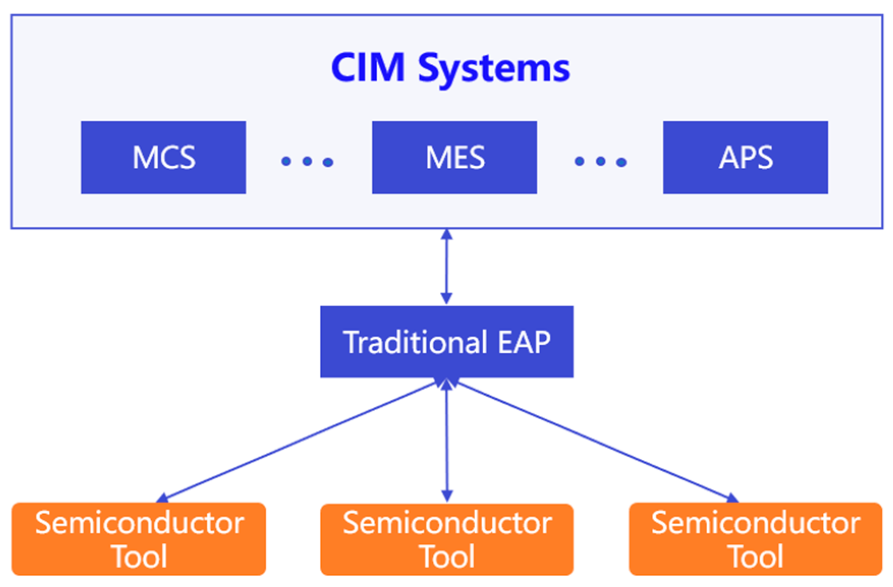
EAP is a basic software system that directly communicates to the manufacturing tools and parses related production information to upper-level applications, such as RMS and MES. EAP always communicates with manufacturing tools under SECS I, SECS II, GEM, and HSMS protocols. The performance of EAP has a significant effect on the efficiency of other systems in CIM for semiconductor manufacturing, such as RMS,
advanced process control (APC) [
12,
13], and MES. As shown in
Figure 1, the traditional EAP acts as a single hub between the manufacturing tools and software systems in CIM. Along with the rising requirements of data analysis for fabs, the traditional EAP cannot meet the current application demand for data collecting and delivery due to the following reasons.
- (1)
The tight coupling between the communication and logic models makes the EAP bloated and unstable. For instance, the occurrence of any exception in EAP may make the EAP power down such that no equipment is reachable;
- (2)
As such, EAP was developed years ago, the deployment of EAP requires plenty of software dependencies, the system runs on an old operating system;
- (3)
With the design of traditional EAP, it takes less consideration for the scalability issue, leading to the fact that it can only handle a couple of manufacturing tools. The extension of manufacturing tools in a fab makes the investment in EAP unbearable.
Due to the continuous advancement in communication and software technologies, such as the
internet of things (IoT) [
14,
15], cloud computing [
16,
17], distributed technology [
18], Big data [
19,
20], container technology [
21,
22,
23], and message queue technology [
24], a new type of EAP can be designed to solve the above-mentioned problems for the traditional EAP.
As far as we know, there are only several studies (see [
25,
26,
27]) that are relative to EAP. However, these studies do not focus on handling the above-mentioned problems for the EAP system. Further, the semiconductor fabs currently adopt the traditional EAP system to communicate to the manufacturing tools with the above-mentioned problems unsolved. It is highly desired to solve these problems, and this motivates us to perform this work.
In this work, a novel implementation framework of a distributed EAP is introduced. The essential difference between the presented EAP in this work and the traditional EAP is that the presented one is loose coupling. To construct such a loose coupling EAP system, the architecture and working mechanism are redesigned. In the new architecture, EAP is composed of two principal platforms, i.e., the management and fundamental platforms. In the meantime, the message queue is adopted for their asynchronous communication. In this way, all models (such as the management model, business logic model, and API model), middleware, and EAP drivers are distributed and deployed on various servers. This ensures that any part of the presented EAP runs independently. Under such a framework, a couple of EAP performance indicators can be enhanced. The first one is the adaptability to disturbances. Under the distributed architecture, the whole EAP system can be stronger and more stable. A tiny exception in the EAP system would not affect the whole system. This greatly improves the robustness of the EAP system by comparing it with the traditional EAP one. Second, with the advantage of container technology, the deployment and maintenance of the EAP system become much easier and fit more operating systems. Third, by integrating distributed architecture and message queue, the whole EAP system is scalable as required.
The rest of the paper is organized as follows. The implementation framework of a distributed EAP system is introduced in
Section 2. Then, based on this framework, detailed operational scenarios of every part of the system are described in
Section 3. Finally, experiments are performed to verify the system performance.
2. Implementation Framework of Distributed EAP System
2.1. Design Philosophy of IF-DEAPS
The new implementation framework of distributed EAP system (IF-DEAPS) is designed under the following three principles so as to ensure the entire system’s stability and meet the performance boundary in actual production conditions:
- (1)
The architecture of IF-DEAPS should be loose coupling;
- (2)
Advanced software technology is required to facilitate its loose coupling and reduce the deployment and management costs;
- (3)
IF-DEAP necessarily has good scalability to meet the requirements of smart manufacturing.
The loose coupling is an essential factor in designing a good distributed EAP system. The loose coupling architecture of IF-DEAPS implies that all the functional platforms in the IF-DEAPS should maximize the independence between them. Further, if functional models or platforms are logically tightly coupled, most of the communications, except the critical synchronous situations, should be performed based on Message Queue so as to achieve decoupling. With the loose coupling architecture of IF-DEAPS, the services or models are allowed to be deployed independently as needed such that the scalability, flexibility, and openness of the system can be enhanced. Meanwhile, IF-DEAPS can avoid a serious influence on the whole system caused by a single node failure such that it is highly fault-tolerant. Consequently, the whole system can benefit from the loose coupling. Additionally, such a design pattern fits the current paradigm of software development.
In order to facilitate the loose coupling and reduce the deployment and management costs, the latest advanced technology, i.e., container technology, is adopted in the IF-DEAPS. Container technology has been a hot topic for the software industry in recent years. As a software platform, Docker is one of the most popular technologies in the container technology list [
28]. Docker provides a standardized unit, called a container, to run the image, in which the developer can pack an application with related dependencies. This mechanism makes the building, shipping, deployment, and maintenance of applications across various scenes, such as development, testing, and production, much easier. Various roles (including developers, testers, operational engineers, etc.) can benefit from it. They can focus on their responsibility with expertise by regarding the container as a black box. For instance, testers can simply build up a container and focus on interface testing and black box testing, and operational engineers can spend more time on IT (Internet Technology) fundamental infrastructures and monitoring system running performance.
Good scalability can make IF-DEAPS more matched with the requirements of smart manufacturing. In smart manufacturing, requirements of a distributed EAP system to connect with manufacturing tools vary from fabs to fabs. Some fabs need only a couple of precise instruments to be equipped to obtain some essential data in some core manufacturing areas, while others stepping deeply into smart manufacturing need all manufacturing tools in the fabs to be connected for data collection as much as possible. The scalability should be mainly considered from the following three aspects: (1) connection scalability; (2) business logic scalability; and (3) management scalability.
The connection scalability refers to the fact that as the number of manufacturing tools grows in a fab, a distributed EAP system can be physically connected to manufacturing tools without restriction of architectural limit. Business logic scalability means that the business logic (i.e., requirements) from user departments can be easily integrated into the system, accurately transformed, and properly executed during the manufacturing process. For instance, recipes 1 and 2 are applied to a type of manufacturing tool in different wafer fabrication scenes. In the actual operations of the tools, they should be correctly deployed according to wafer fabrication scenes, i.e., wafer fabrication processes. Management scalability means that with the increments of connection, the system should have a single place to manage and maintain the connections properly.
2.2. Architecture of IF-DEAP
According to the design principles mentioned above, the system architecture of IF-DEAPS is designed as shown in
Figure 2, which contains a management platform, message queue, and a fundamental platform. In the architecture, semiconductor tools and sensors are omitted.
In the architecture, the management platform acts as a brain to control and monitor the whole system, the message queue is responsible for delivering data through the system, like the nervous system in the brain, and the fundamental platform works as a limbs to execute commands and collect data.
The management platform consists of a management model, a business logic model, a monitor model, a master model, an application interface (API) model, and a database. All these models can be sorted for different purposes. The management model, monitor model, and master model are for management; the business and API models are for implementing business-related tasks; and the database is used to store models’ data across the management platform and intermediate data that may be supplied to other systems. The sortation of components at the management platform is not only based on functionality but also on the system interactions.
The business-related part is a port to interact with users and the outside systems. Therefore, it should be standalone and provide the system functions directly and clearly. The core function of the management part is to monitor and manage the distributed EAP drivers at the fundamental platform. In order to implement these key functions efficiently, master and agent models are introduced in the designed IF-DEAPS. The agent model is deployed prior to each EAP driver and helps to deploy, configure, and monitor the health conditions of the associated EAP driver. The number of agent models equals the number of EAP drivers. The master model is responsible for communicating with agent models to transmit action commands and collect data as the management model requires.
In IF-DEAPS, shown in
Figure 2, the message queue has a variety of choices in the current software development industry. Kafka [
29], ActiveMQ, RabbitMQ, and RocketMQ are the most popular ones in this area. By analyzing the virtues and defects of these message queues, Kafka is selected as the message queue in this architecture. The detailed reasons persuading us to use Kafka are summarized as follows: (1) Kafka is designed as a distributed architecture that naturally fits a high throughput system; (2) it has good document and community support during the implementation; and (3) the fact that supports multiple development languages makes this framework implementable without language restriction.
The fundamental platform of IF-DEAPS is a loose and edge platform that hosts EAP drivers. The drivers at the platform connect directly to manufacturing tools to collect data and control the tools via diverse protocols, such as SECS/GEM, HTTPS, and others. The agent models described above, at the platform, are patterned with the master model to monitor and manage EAP drivers. The detailed operational mechanism of IF-DEAPS is described next.
3. Operational Mechanisms
3.1. The Fundamental Platform
The fundamental platform architecture of IF-DEAPS is shown in
Figure 3. The essential function of EAP is to collect wafer processing data from manufacturing tools, and parses commands to the tools. As
Figure 3 shows, each EAP driver is bidirectionally communicated with the equipment and message queue. The agent model is an associated model to ensure that the corresponding EAP driver works in a good state by configuring the EAP driver and monitoring the EAP driver’s health condition, etc. Typical operational scenarios of the fundamental platform, including the command executing scenario, data collecting scenario, EAP driver configuring scenario, and EAP driver health condition monitoring scenario are discussed as follows.
3.1.1. Command Executing and Data Collecting Scenarios
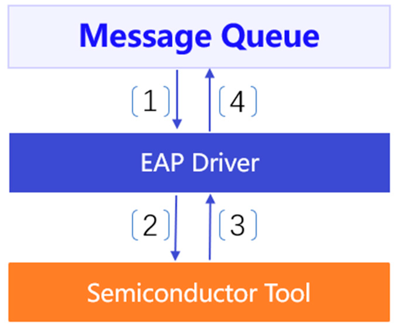
Command executing and data collecting scenarios of the distributed EAP system are shown in
Figure 4, and the operational mechanism includes the following four steps:
- (1)
The message queue pushes a data-collecting command to an EAP driver. Such a command necessarily gives the corresponding data information, such as wafer processing parameters of a manufacturing tool, collecting time, or other specific requirements;
- (2)
According to the equipment protocol, the EAP driver translates the collecting command and executes it on a tool;
- (3)
After the execution, the tool parses the data back to the EAP driver;
- (4)
After data are received by the EAP driver, the EAP driver transforms the data into JSON format and pushes them to the message queue.
Steps (1) and (2) together form the command executing scenario, while Steps (3) and (4) together form the data collecting scenario.
3.1.2. EAP Driver Configuring Scenario
The EAP driver configuring scenario is shown in
Figure 5. Sequentially performing the following five steps forms the operational mechanism of this scenario:
- (1)
The message queue pushes an updated configuration command to an agent model;
- (2)
The agent model sends this updated command to the corresponding EAP driver, and then the EAP driver turns into an updated mode;
- (3)
The agent model pulls the latest configuration information from the message queue;
- (4)
The agent model updates the EAP driver configuration files;
- (5)
When the update succeeds, the agent model turns the EAP driver into a normal mode and sends feedback to the message queue.
3.1.3. EAP Driver Health Condition Monitoring Scenario
The EAP driver, health condition monitoring, is followed by the deployment of a distributed EAP driver and continuously works until the termination of the EAP driver. The EAP driver deployment refers to the initialization of the EAP driver on a server with initial settings, configurations, and default parameters. The EAP driver health condition monitoring scenario is shown in
Figure 6, and the operational mechanism of this scenario contains the following four steps:
- (1)
After the EAP driver deployment is performed, the EAP driver sends a success message to the message queue;
- (2)
The corresponding associated agent model obtains the success message from the message queue;
- (3)
The agent model checks the health condition data, such as the application process ID, disk usage, network speed, etc., from the environment of the EAP driver;
- (4)
The agent model sends the health condition data to the message queue.
According to the required monitoring cycle, the agent model repeats Step (2) to Step (4) periodically.
3.2. Message Queue
The message queue enables an asynchronous data communication mechanism between two systems. The main function of the message queue is data communication, especially applied to the decoupled micro-service architectures. A stack of data is regarded as messages logically, and they are stored in a queue until they are processed. In general, the message queue technology can be used to decouple heavyweight data processing, buffer work, and batch work, as well as to smooth workloads as a balancer.
In this work, Apache Kafka is selected for the message queue in IF-EAP. The reason that lies behind this can be concluded into three main points: (1) distributed structure; (2) data streaming pipeline functionality; and (3) container composed and easy to install.
Kafka is a versatile, distributed, and replicated framework that implements the message queue by using a publish–subscribe process. It is an open-source software maintained by a community. In the operating mechanism, the publisher is named as “producer” while the subscriber is named as “consumer”. Producer commits data, and the consumer receives data. The general infrastructure of Kafka is illustrated in
Figure 7.
As shown in
Figure 7, producers send messages to topics. The messages are known as data. A producer can send data to one topic only at a time. Additionally, producers are able to send messages asynchronously and point-to-point. Consumers read messages from Topics. They maintain the partition offset to consume data from topics. The actual data are stored in a key-value format with a timestamp indexed. Then, the data are immutable. A topic is a stream of data subscribed to by multiple consumers. It is the highest level of abstraction that Kafka provides. Partitions are an ordered, immutable sequence of data that are continuously appended. It cannot be further divided across disks.
The high availability is performed by the distributed architecture since the data are attainable from multiple partitions. Additionally, the fault tolerance in Kafka is realized by copying the partition data to other brokers, which are known as data replicas. Each broker holds one or more partitions, and each of them can either be the replica or the leader for the topic. In the Kafka mechanism, the read and write operations go through to a leader of a topic, and the leader coordinates with replicas for the data updating.
It follows from
Figure 2 that Kafka serves as the main data pipeline between the EAP management platform and the fundamental platform in this work. The fundamental platform serves as a data producer, while the EAP management platform serves as a data consumer. Internally, the transmitted data obtains stored in one topic where the logical grouping of partitions performs. Partitions are the actual storage of the data, while the data are spread over multiple partitions across the cluster within different machines. Externally, the message queue serves as a bridge connecting two separate systems (i.e., the EAP management and fundamental platforms) so as to form an entire distributed EAP system.
3.3. Management Platform
The management platform architecture is shown in
Figure 8. As the management platform is a port for users or other systems to use, these outside parts are added into IF-DEAPS. Web UI and APP are graphic user interfaces that help users manage the distributed EAP system and manipulate wafer fabrication tools through the system. As the EAP system is fundamental to collecting data and manipulating wafer fabrication tools, other systems, such as APC, RMS, and
fault detection and classification (FDC) systems, in fabs need to obtain data from IF-DEAPS via APIs.
In the management platform, the management model, business logic model, and API model are fully or partially exported to web UI or other systems to supply services. Master model, monitor model, and database are mainly focused on supporting the implementation of services. For instance, the data collecting service is performed by the management model. When a user triggers this service in web UI, web UI then parses related parameters to the management model. After analyzing and transforming to the management model, a command is sent to the master model that is responsible for performing this command. Some typical operational scenarios are discussed next, including the data checking scenario, updating configuration scenario, and checking EAP driver status scenario.
3.3.1. Data Checking Scenario
In the data checking scenario, when a user wants to check equipment data (including real-time and historical data), if the user is querying the real-time data, then the data sources should be the EAP drivers; while if the user is querying the historical data, the data source should be the database. The detailed scenario is shown in
Figure 9, and the operational mechanism contains the following steps:
- (1)
A user makes a command to check a series of data. This command can be made through APP, Web UI, or other systems invoking API service. Further, if the command is sent by other systems, it passes to the API model; while if the command is sent by APP and Web UI, it passes to the business logic model;
- (2)
If the command is passed to the API model, this command is then transferred to the business logic model;
- (3)
The business model analyzes the command, i.e., determining whether the required data are real-time or historical data. If the data are real-time ones, the business model sends this command to the master model so as to obtain the data from the EAP drivers in real-time, while if the data are historical ones, the business model sends this query command to the database;
- (4)
If the database receives this command, it resolves the query and sends the proper data to the business logic model;
- (5)
If the master model receives this command, it analyzes the command, specifics the proper EAP driver, repackages the command with EAP parameters, and sends the command to topics in the message queue;
- (6)
After the required data are collected from the EAP driver and sent back, the message queue pushes the data to the master model;
- (7)
The master model sends the data to the business logic model;
- (8)
After receiving the data, the business logic model manipulates the data according to the proper business logic and sends them back to the APP, Web UI, or the API model accordingly;
- (9)
If the API model receives the required data, it sends a feedback message from the business logic model to other systems.
3.3.2. Configuration Updating Scenario
Configuration updating refers to the scenario that a user wants to change a specific EAP driver configuration or a group of EAP drivers related to a type of wafer fabrication tool. This scenario is shown in
Figure 10, and the operational mechanism in this scenario contains the following steps:
- (1)
A user makes a configuration updating command through the APP or Web UI and then passes the command to the business logic model. In this stage, based on the authorization consideration, this command cannot be executed by the API model;
- (2)
The business logic model queries the latest configuration data in the database;
- (3)
The database sends back the latest configuration data to the business logic model;
- (4)
If the updating configuration is different from the latest stored one, the business logic model packages the command with new configuration parameters and an EAP driver list required to be updated to the master model and the database;
- (5)
The master model specifies an EAP driver or EAP drivers and sends the updating configuration data to the message queue;
- (6)
After the EAP driver configuration is updated, the massage queue pushes the successfully updated information to the master model;
- (7)
The master model sends the successful information to the business logic model;
- (8)
The business logic model sends the successful information to the APP and Web UI.
3.3.3. EAP Driver Status Checking Scenario
The EAP driver status-checking scenario is a continuously monitoring scenario. In an actual production environment, all EAP drivers are involved. Note that in the following descriptions, the checking status scenario for only one EAP driver is introduced. This scenario is shown in
Figure 11, and the operational mechanism in this scenario contains the following steps:
- (1)
The master model obtains the successfully deployed message of an EAP driver from the message queue. Then, it records the EAP driver information and adds the information to a monitor list;
- (2)
The master model asks the message queue to add a new EAP driver monitoring topic with parameters;
- (3)
The message queue pushes a successful topic creation message back to the master model;
- (4)
At the time when the message queue receives the EAP driver status, it pushes the EAP driver health condition information to the master model;
- (5)
After the required health conditions of an EAP driver are collected by the master model, the model pushes them to the database.
Steps (1)–(3) are performed once an EAP driver is deployed, while Steps (4)–(5) are repeatedly performed to monitor the health conditions of an EAP driver.
3.4. Advantages of the Proposed Distributed EAP System
Compared with the traditional EAP, the common services, including the communication with and manipulation of manufacturing tools under the proper business logic, are fully implemented in IF-DEAPS at the fundamental and management platforms. Moreover, due to the distributed architecture of IF-DEAPS, the adaptability and scalability are enhanced greatly.
The enhancement of adaptability means a better fault tolerance of the system with a lower cost. For the traditional EAP, any exception, such as the environmental problem and bugs in the traditional EAP, may bring a corresponding manufacturing tool offline. If another traditional EAP is prepared in advance, this can solve the single node (i.e., a traditional EAP) failure problem. However, a redundant EAP containing both business logic and communication parts is expensive and wastes a lot of resources. For IF-DEAPS, all models, middleware, and EAP drivers are distributed and deployed on various servers. This ensures that any part of IF-DEAPS works independently at a lower cost. Furthermore, when a bug occurs in some part of IF-DEAPS, another equivalent part can make up for that so as to ensure that manufacturing tools can still operate without being affected.
The improvement in scalability is shown as follows. If more manufacturing tools with the same type are required to be connected to IF-DEAPS, IF-DEAPS can be cheaply scaled. For example, suppose that a fab has twenty manufacturing tools with IF-EAPS being already installed. When the fab purchases another twenty manufacturing tools, the IT team only needs to deploy twenty more EAP drivers. However, a traditional EAP has a limit on the number of manufacturing tools to be connected. Assume that a traditional EAP can connect twenty manufacturing tools. Thus, in this example, if the fab adopts the traditional EAPs to connect manufacturing tools, then another traditional EAP is needed to connect the newly purchased manufacturing tools. This also causes a heavy investment in the EAP system.
As discussed above, IF-DEAPS can provide users with a more stable, cheap, and easy way to communicate with and manipulate manufacturing tools.
4. Performance Evaluation
The purpose of the distributed EAP system performance test is to evaluate the entire system’s stability and the performance boundary under an actual production condition. In this work, the Jmeter tool is applied to perform such a performance test.
Table 1 lists two testing scenarios corresponding to a short-term test and a relative long-term test.
Table 2 shows the test environment. Additionally, nine indicators are used to evaluate the performance of the EAP system, including:
- (1)
Request success ratio (RSR): The ratio of successful interface requests response to the total requests;
- (2)
CPU consumption (CPUC): The CPU resource consumption during the EAP system performance test;
- (3)
Memory consumption (MC): The memory resource consumption during the EAP system performance test;
- (4)
Time boundary of 90% data (TB-90%): The time boundary that is no less than the request–response time of 90% data;
- (5)
Time boundary of 95% data (TB-95%): The time boundary that is no less than the request–response time of 95% data;
- (6)
Time boundary of 99% data (TB-99%): The time boundary that is no less than the request–response time of 99% data;
- (7)
Minimum time consumption (MinTC): The minimum time consumed by the interface response;
- (8)
Maximum time consumption (MaxTC): The maximum time consumed by the interface response;
- (9)
Average time consumption (ATC): The average time taken by the interface response.
For Scenarios A and B, the performance tests of the EAP system are carried out by observing the request–response data of nine key interfaces for 24 h and 3 × 24 h, respectively. The detailed testing results for scenarios A and B are summarized in
Table 3 and
Table 4.
As shown in
Table 3 and
Table 4, the interface request success rate reaches 100% for all interfaces. In the meantime, the CPU and memory resource consumption is controlled within 70%, which is in a safe and controllable range for applications. More specifically, it follows from
Table 3 and
Table 4 that the TB-90%, TB-95%, and TB-99% for all interfaces are controlled under a millisecond level for both Scenarios A and B. Nevertheless, values of TB-90%, TB-95%, and TB-99% of parameter and parameter ratio setup under Scenario A are much larger than that under Scenario B. This indicates that under Scenario A (a relatively short-term scenario), the time boundaries that are no less than the request–response time of 90%, 95%, and 99% of data are larger than that under Scenario B (a relative long-term scenario). It implies that during a much longer time period, the proposed distributed EAP achieves a more stable performance since the ratio of the long request–response time to all response time decreases.
Further, the values of MinTC for most of the interfaces under Scenario A are correspondingly larger than that under Scenario B, while the value of MaxTC for each interface under Scenario B is larger than that under Scenario A. The reason for this phenomenon is that during a much longer time period, it would have a higher probability to collect unusual data under extreme situations. Note that the value of MaxTC in
Table 3 or
Table 4 represents an abnormal event caused by the network dithering that is commonly seen in practice. However, it follows from
Table 3 and
Table 4 that the values of ATC under Scenarios A and B have no significant differences except for parameter and parameter ratio setup interfaces. For parameter and parameter ratio setup interfaces, the values of ATC under Scenario B are much smaller than those under Scenario A. It implies that the distributed EAP can achieve a more stable performance during a much longer time period.
All in all, based on the testing results of RSR, CPUC, MC, TB-99%, and ATC summarized in
Table 3 and
Table 4, we conclude that the proposed distributed EPA system achieves good performance under both Scenarios A and B.
Further, the parameter interface is important for the components in the management platform of the distributed EAP system to obtain the parameter data from manufacturing tools. It is one of the most frequently invoked interfaces used in the production environment. It follows from
Figure 12 and
Figure 13 that the changing of the light green line representing the parameter interface is usually smooth. It implies that the distributed EAP system works properly and achieves a good performance in response. There are also some needle jumps of the light green line occurring accidentally. Those are usually caused by network problems and computing resource competition problems occasionally. Notice that they are extraneous to the distributed system itself. Meanwhile, even if the occasional problems occur, the system can respond to them properly as required.
Table 3 and
Table 4 and
Figure 12 and
Figure 13 show the stability of the proposed distributed EAP system. Further, some quantitive results by comparing with the currently adopted EAP system from the other three semiconductor manufacturing software companies are also obtained. During the confidential and commercial regulations, we cannot disclose the names of other software companies, and they are named Companies A, B, and C. The comparisons are performed in the same manufacturing line of a semiconductor fab in China. The comparison results are shown in
Table 5, in which TPS presents the number of Transactions per Second. Additionally, due to non-disclosure agreements with the semiconductor fab, we cannot show the detailed quantitative comparison results. Nevertheless, the order of magnitude of TPS that can be reached using each method is presented in
Table 5. It follows from
Table 5 that IF-DEAP is significantly better than the others in terms of the efficiency of TPS.
5. Conclusions
EAP systems are widely used to interconnect manufacturing tools so as to parse related production information to the upper applications in semiconductor fabs. They are the fundamental components in MES as well and play an important role in the efficiency of other systems, such as RMS and APC. The traditional EAP acts as a single node to interconnect a specified number of manufacturing tools without scalability. It couples the communication model with the logic model tightly, making the EAP bloated and unstable. Further, it has been developed for dozens of years and fails to be compatible with new technologies that can make the EAP system perform better. To solve such problems, this work designs a new framework of a distributed EAP system such that the management platform acts as a brain to control and monitor the whole system, the message queue is responsible for delivering data through the system, like the nervous system in the brain, and the fundamental platform works as limbs to execute commands and collect data. Under such a distributed architecture, a tiny exception in the EAP system would not affect the whole system. This greatly improves the robustness of the EAP system by comparing it with the traditional EAP system. Additionally, by combining the distributed architecture and message queue, the scalability of the EAP system is greatly improved. Experiments show that the designed distributed EAP system has good performance in terms of stability.
Our future work aims to improve the designed distributed EAP system to support more PLC protocols and provide a more convenient way for users to program the business logic.


