A Hierarchical Control Strategy Based on Dual-Vector Model Predictive Current Control for Railway Energy Router
Abstract
:1. Introduction
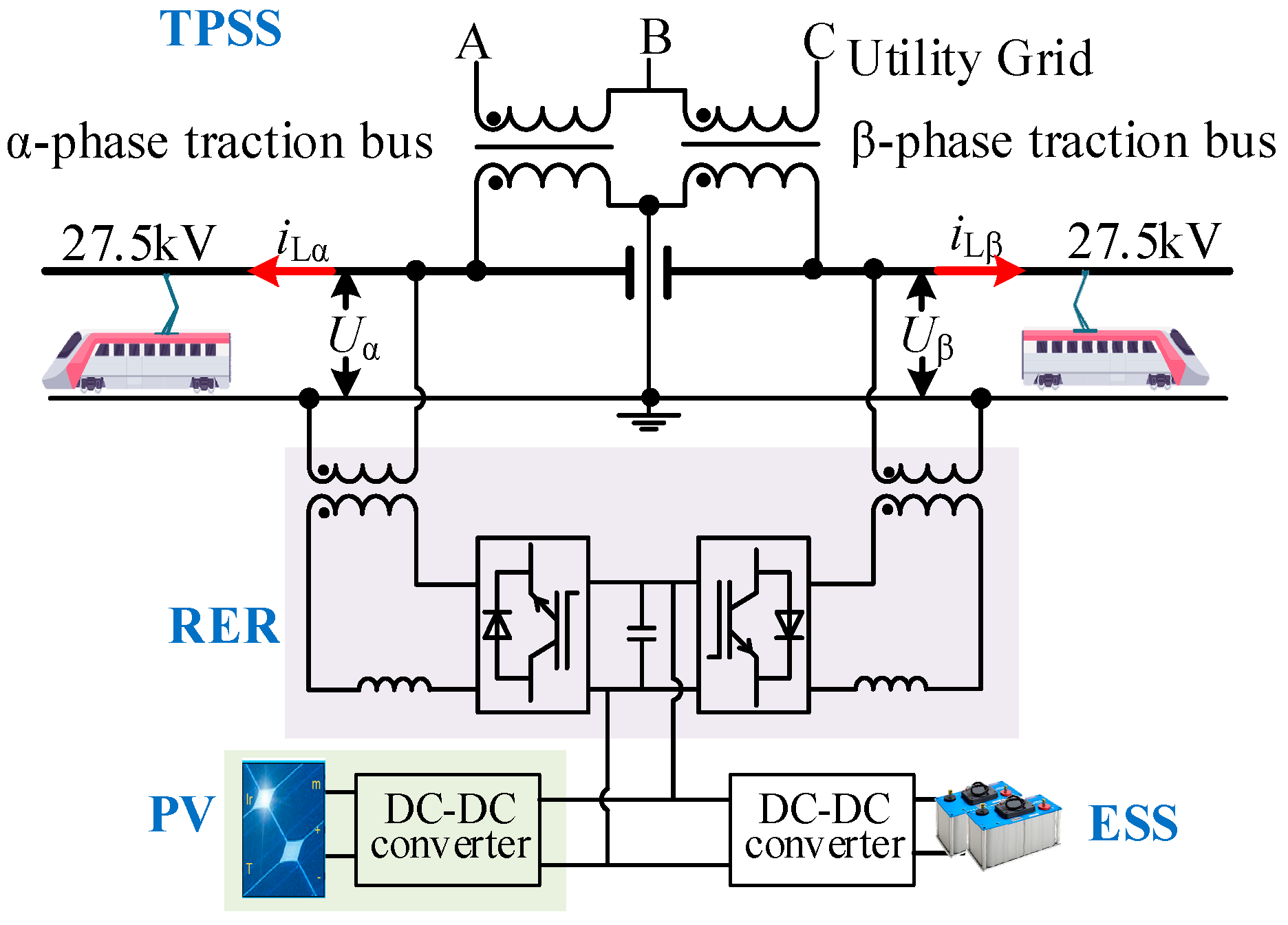
2. System Structure of RERs
3. Results of Operating Modes and Time-Segmentation Energy Allocation Strategy for RERs
3.1. Four Operating Modes of RERs
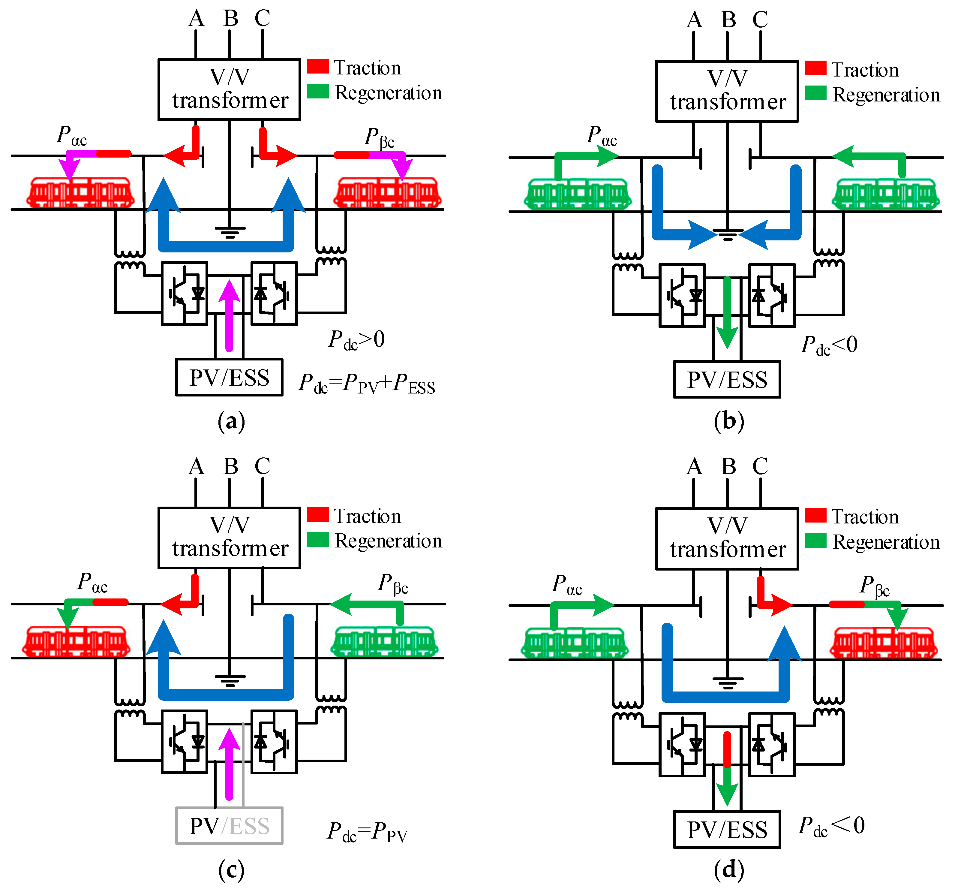
- Mode 1: peak-clipping discharge state. In this situation, the loads satisfy (PLα + PLβ − PPV) ≥ PH, and the ESS satisfies SOC > SOCmin. Then, the ESS is in discharge state. The power generated by the PV system or ESS is distributed to both traction buses through the RER. Then, a certain amount of active power is transferred from one traction bus to the other to achieve power balance. Meanwhile, the reactive power of each bus is independently compensated.
- Mode 2: recovery regenerative braking state. As shown in Figure 2, the loads meet (PLα + PLβ − PPV) < 0, and the ESS satisfies SOC < SOCmax. The ESS enters the charging state. RBE is first absorbed by the load on the same traction bus, and the remaining part is transferred to the other traction bus to be absorbed by the RER. Then, the unconsumed RBE is absorbed by the ESS, and the part that cannot be absorbed is fed back to the upstream utility grid. The energy generated by the PV system is first absorbed by the load, and the excess energy is absorbed by the ESS (if the ESS is still capable), otherwise it is discarded.
- Mode 3: power transmission state. In this scenario, the ESS does not work. The SOC of the ESS exceeds the effective threshold, or the loads meet Plow ≤ (PLα + PLβ − PPV) < PH, whether in traction state or in regenerative braking state.
- Mode 4: valley-filling adjustment state. In this mode, the loads meet 0 ≤ (PLα + PLβ − PPV) < Plow. Specifically, if the instantaneous SOC(t) is less than the initial SOCSOC (SOCSOC0), the ESS enters the charging state, otherwise it enters the standby state. The SOC values should be the same during the alternation of the daily cycle to keep the ESS continuously working.
3.2. Time-Segmentation Energy Allocation Strategy
- Data processing: This step involves initializing variables, detecting data, and calculating the traction load. The initialized variables include the threshold values of the SOC (SOCmin, SOCmax), the initial value of the SOC (SOC0), the rated capacity of the inverter (Smax), and the maximum discharge power of the ESS (PBM).
- Judge mode: First, based on the historical measured data, the time period, t ∈ (t1, t2), in which the maximum demand is probable to appear is estimated and set as the maximum demand mode. Then, different peak-valley values are set for the maximum demand mode, and the peak-shaving-valley-filling mode, respectively.
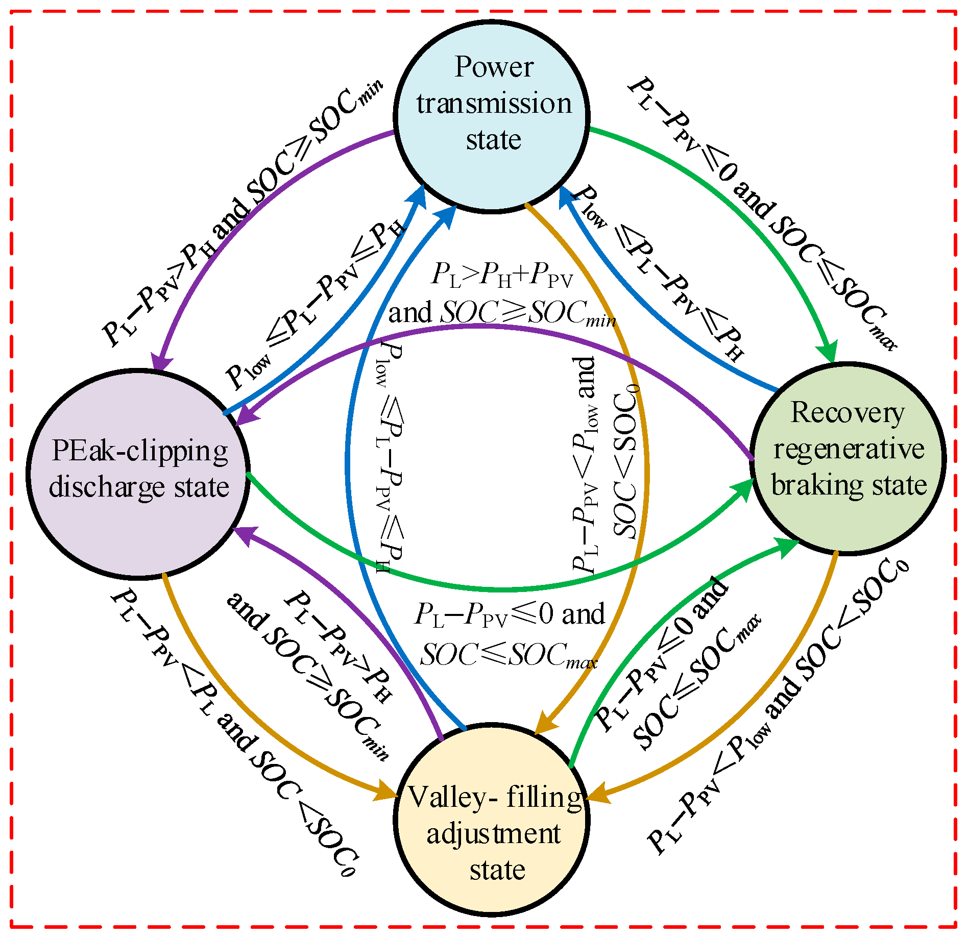
- Judge state: Based on the instantaneous power of the traction load and PV system, and the instantaneous SOC(t) of the ESS, as well as the peak and valley values obtained in the previous step, the system operation status is judged in real time. Specifically, it is divided into peak-clipping discharge state, recovery regenerative braking state, power transmission state, and valley-filling adjustment state. The specific judgment process is shown in Figure 3, and the transition relationships among different operation states are shown in Figure 4.
4. Hierarchical Control Strategy
4.1. Reference Signal Generation
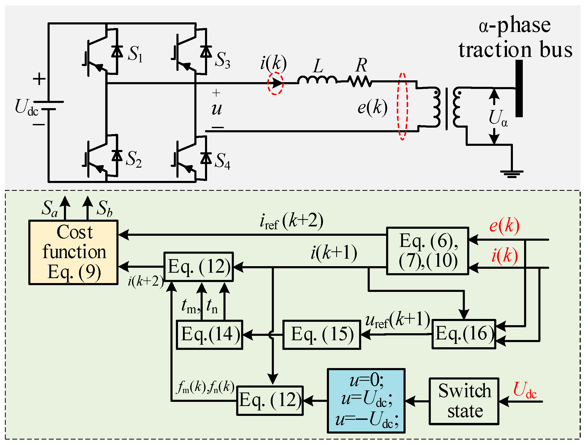
4.2. Modeling and Control of Back-to-Back Inverter
4.3. Control of DC/DC Converter
5. Analysis of Simulations and Experiments
5.1. HIL Experimental Verification
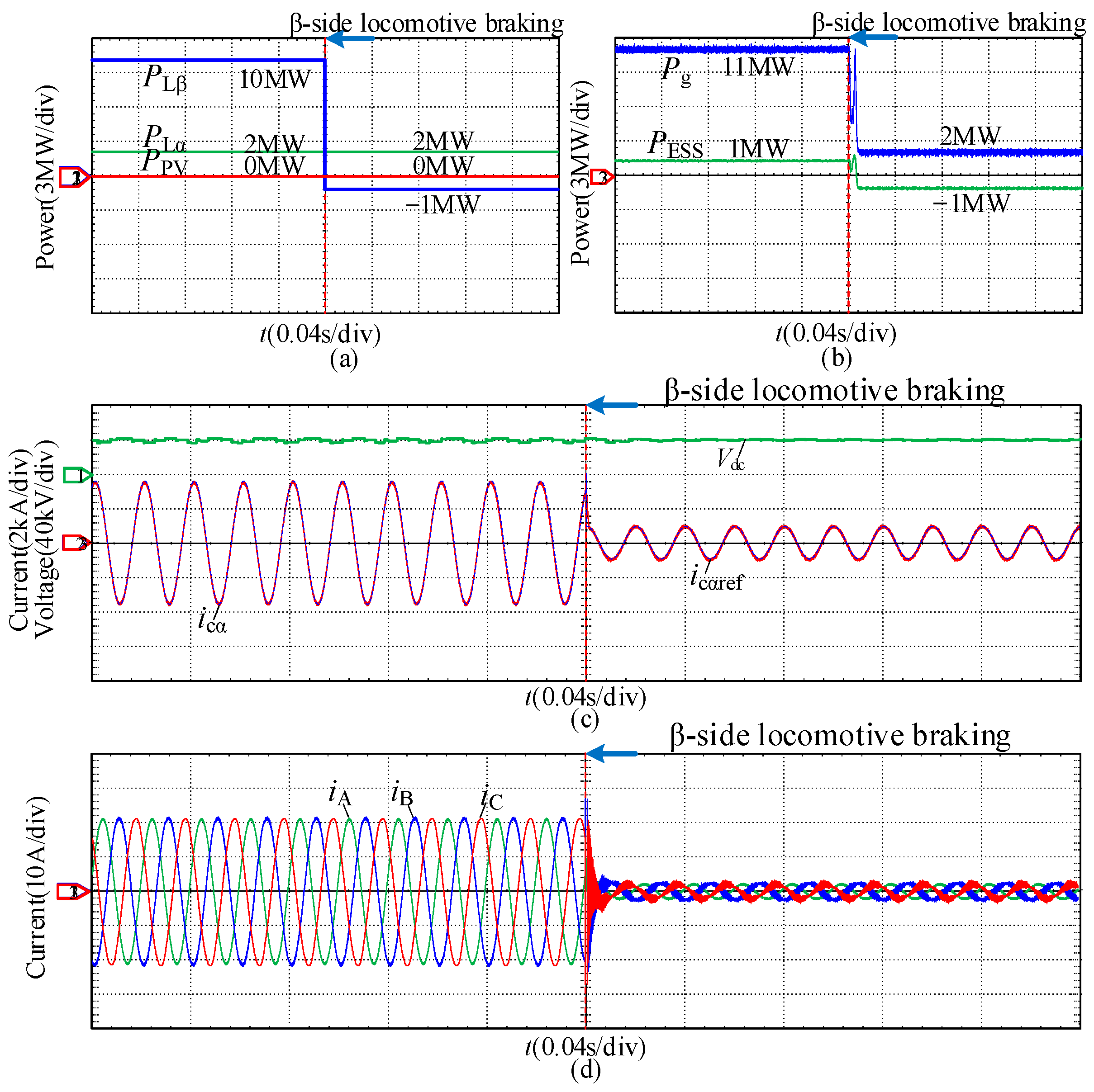
- Power transmission state and recovery regenerative braking state: The experimental waveforms are described in Figure 9.
- 2.
- Peak-clipping discharge state and valley-filling adjustment state: The experimental waveforms are described in Figure 10.
5.2. Typical Daily Measured Load Data Verification
5.3. Comparison with Previous Works
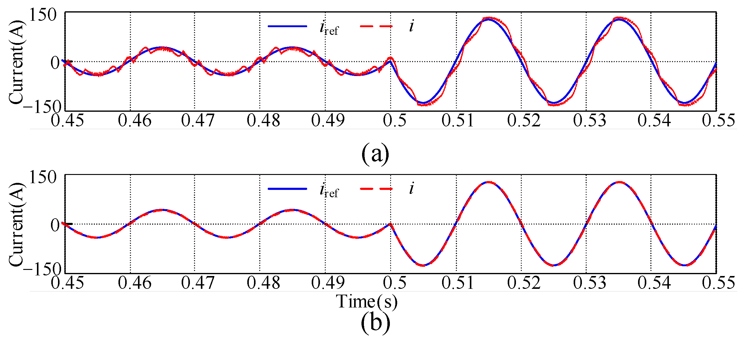
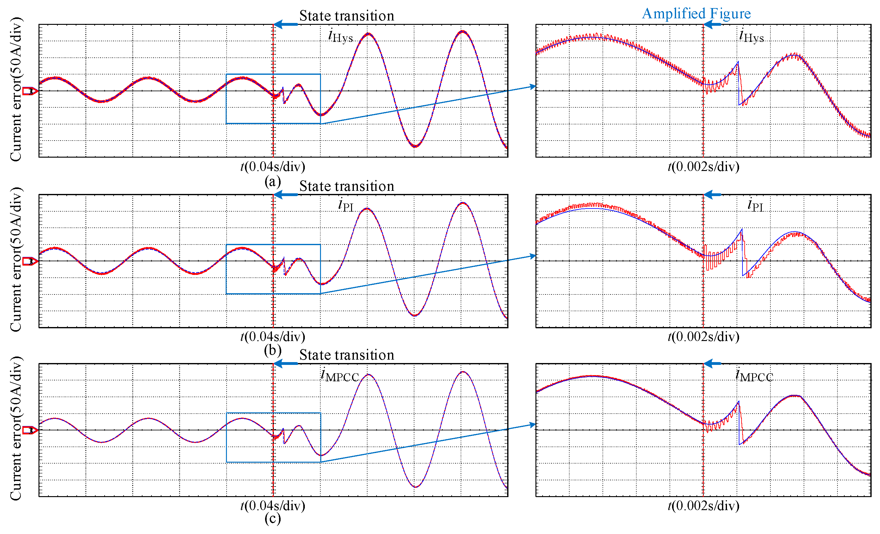
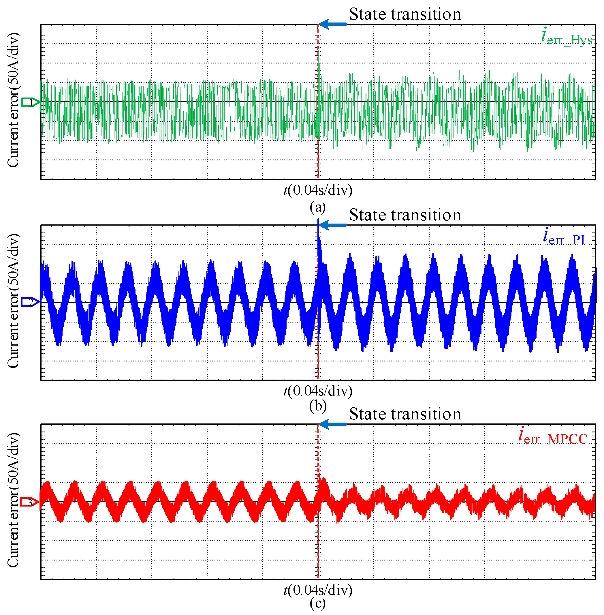
- Comparison of different control strategies: hysteresis control [16,17,18,19], PI control [20], and the proposed dual-vector MPCC strategy. The specific operating conditions involve transitioning from recovery regenerative braking state to peak-clipping discharge state. Figure 15 illustrates the current of inverter α following the application of three different control strategies. It can be observed that during transient processes, when employing the proposed dual-vector MPCC strategy, there is high precision in tracking the reference current with minimal current deviation. Figure 16 shows the current-tracking error when three different control strategies are adopted for converter α. It can be observed that the current error is minimized when employing the dual-vector MPCC strategy. Therefore, the current-tracking error can be employed effectively, and current-tracking accuracy can be improved by using the proposed dual-vector MPCC strategy.
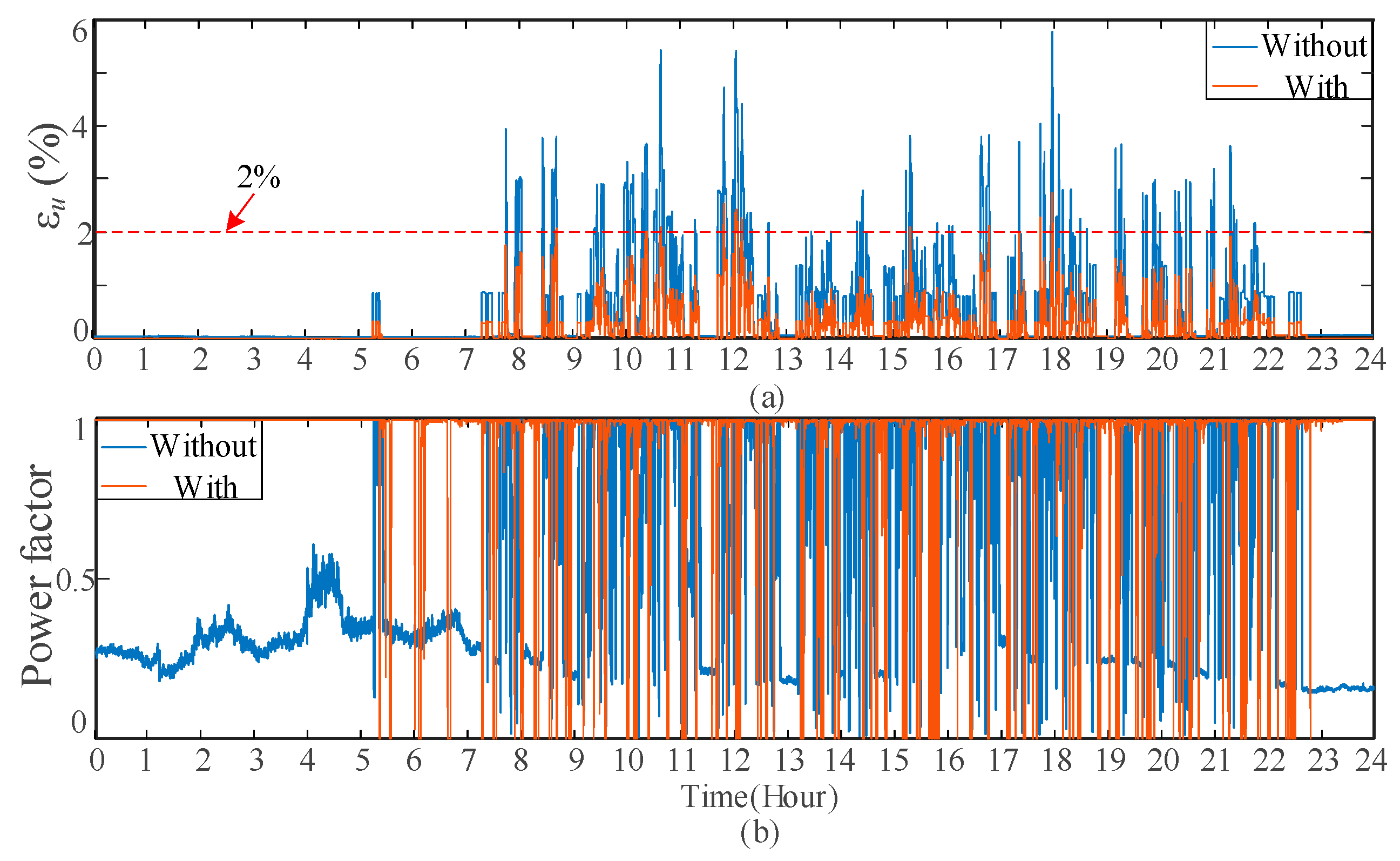
- Comparison of the proposed time-segmentation energy allocation strategy with the previous strategy: Table 2 shows the simulation results with different energy allocation strategies. With the time-segmentation energy management strategy, the power demand reduction rate increases from 5.51% to 10.36% with the same RBE recovery rate, PV consumption rate, and power quality improvement effect. The results suggest that the time-segmentation energy allocation strategy proposed in this paper can simultaneously reduce the maximum demand and PV consumption, and recover regenerative braking energy, as well as improve power quality.
6. Conclusions
Author Contributions
Funding
Data Availability Statement
Conflicts of Interest
Nomenclature
| RER | Railway energy router |
| PV | Photovoltaic |
| ESS | Energy storage system |
| MPCC | Model predictive current control |
| RBE | Regenerative braking energy |
| PI | Proportional–integral |
| PR | Proportion resonance |
| SOC | State of charge of the ESS |
| SOGI | Second-order generalized integrator |
| MPPT | Maximum power point tracking |
| Variables and Symbols | |
| VSCα, VSCβ | Single-phase voltage source inverters of railway energy router |
| Tα, Tβ | Step-down transformers |
| Pg | Active power of the upstream utility grid (MW) |
| PPV | Power generated by a PV system (MW) |
| PLα, PLβ | Active power of α/β traction loads (MW) |
| Pcα, Pcβ | Active power compensated by VSCα and VSCβ (MW) |
| PH | Peak-clipping power value (MW) |
| Plow | Valley-filling adjustment power value (MW) |
| PBM | Maximum discharge power of the ESS (MW) |
| PL | Total active power of load (MW) |
| PESS | Power generated by the ESS (MW) |
| Qcα, Qcβ | Reactive power compensated by VSCα and VSCβ (MVar) |
| SOCmin, SOCmax | The upper and lower SOC limits of the ESS (%) |
| SOC0 | Initial SOC of the ESS (%) |
| Uα(t), Uβ(t) | Voltages of α- and β-phase traction feeders (kV) |
| Iα(t), Iβ(t) | Currents of α- and β-phase traction feeders (kA) |
| L, R | Inductor and resistor of the circuit (mF/Ω) |
| u, i | Output voltage and current of VSCα (kV/kA) |
| e | Output voltage of grid (kV) |
| iref(k) | Present reference current (kA) |
| iref(k + 1) | One-step future reference current (kA) |
| i(k + 2) | Two-step future current (kA) |
| iref(k − 1) | One-step past reference current (kA) |
| iref(k − 2) | Two-step past reference current (kA) |
| u(k + 1) | One-step future voltage (kV) |
| uoutm, uoun | First voltage and second voltage (kV) |
| tm, tn | Working time of uoutm and uoun (s) |
| Ts | Sampling period (s) |
| fm(k), fn(k) | Derivatives of the output current produced by uoutm and uoun |
| Gm, Gn | Voltage cost function of uoutm and uoutn |
References
- Hu, H.; Ge, Y.; Huang, Y.; Ai, L.; Zhou, Y.; He, Z.; Gao, S. A novel “Source-Network-Train-Storage” integrated power supply system for electric railways. Proc. CSEE 2022, 42, 4374–4391. [Google Scholar]
- Khayyam, S.; Ponci, F.; Goikoetxea, J.; Recagno, V.; Baglinano, V.; Monti, A. Railway energy management system: Centralized-decentralized automation architecture. IEEE Trans. Smart Grid 2016, 7, 1164–1175. [Google Scholar] [CrossRef]
- Ceraolo, M.; Lutzemberger, G.; Meli, E.; Pugi, L.; Rindi, A.; Pancari, G. Energy storage systems to exploit regenerative braking in DC railway systems: Different approaches to improve efficiency of modern high-speed trains. J. Energy Storage 2018, 16, 269–279. [Google Scholar] [CrossRef]
- Song, Y.; Song, W. A novel dual speed-curve optimization based approach for energy-saving operation of high-speed trains. IEEE Trans. Intell. Transp. Syst. 2016, 17, 1564–1575. [Google Scholar] [CrossRef]
- Wu, M.; Dai, C.; Deng, W.; Gao, Y.; Chen, H.; Chen, W. Back-to-back PV generation system and its control strategy for electrified railway. Power Syst. Technol. 2018, 42, 541–547. [Google Scholar]
- Deng, W.; Deng, C.; Han, C.; Chen, W. Back-to-back hybrid energy storage system of electric railway and its control method considering regenerative braking energy recovery and power quality improvement. Proc. CSEE 2019, 39, 2914–2924. [Google Scholar]
- Deng, W.; Dai, C. A multifunctional energy storage system with fault-tolerance and its hierarchical optimization control in AC-fed railways. IEEE Trans. Power Del. 2022, 37, 2440–2452. [Google Scholar] [CrossRef]
- Guo, P.; Xu, Q.; Yue, X.; Ma, F.; He, Z.; Luo, A.; Guerrero, J.M. Analysis and control of modular multilevel inverter with split energy storage for railway traction power conditioner. IEEE Trans. Power Electron. 2020, 35, 1239–1255. [Google Scholar] [CrossRef]
- Ma, F.; Wang, X.; Deng, L.; Zhu, Z.; Xu, Q.; Xie, N. Multiport railway power conditioner and its management control strategy with renewable energy access. IEEE J. Emerg. Sel. Top. Power 2020, 8, 1405–1418. [Google Scholar] [CrossRef]
- Cui, G.; Luo, L.; Liang, C.; Hu, S.; Wang, T. Supercapacitor integrated railway static power conditioner for regenerative braking energy recycling and power quality improvement of high-speed railway system. IEEE Trans. Transp. Electrif. 2019, 5, 702–714. [Google Scholar] [CrossRef]
- Chen, J.; Hu, H.; Ge, Y.; Wang, K.; He, Z. An energy storage system for recycling regenerative braking energy in high-speed railway. IEEE Trans. Power Del. 2021, 36, 320–330. [Google Scholar] [CrossRef]
- Chen, H.; Che, Y.; Fu, R.; Wang, X.; Zhu, H. Study on regenerative braking energy utilization and power quality control in electrified railways. In Proceedings of the 2018 IEEE International Power Electronics and Application Conference and Exposition (PEAC), Shenzhen, China, 4–7 November 2018. [Google Scholar]
- Deng, W.; Dai, C.; Zhang, H.; Zhang, L.; Li, M.; Wu, Z. Research on comprehensive optimization control method for traction photovoltaic generation system of complex electrified railway. Proc. CSEE 2020, 40, 5849–5865. [Google Scholar]
- Luo, P.; Li, Q.; Zhou, Y.; Ma, Q.; Sun, J. Multi-application strategy based on railway static power conditioner with energy storage system. IEEE Trans. Intell. Transp. Syst. 2021, 22, 2140–2152. [Google Scholar] [CrossRef]
- Zhang, Y.; Hu, H.; Geng, A.; Cheng, J.; Ge, Y.; Wang, K. Capacity optimization configuration of hybrid energy storage system for electrified railway considering peak shaving and valley filling. Electr. Power Autom. Equip. 2023, 43, 44–50. [Google Scholar]
- Luo, A.; Wu, C.; Shen, J.; Shuai, Z.; Ma, F.J. Railway static power conditioners for high-speed train traction power supply systems using three-phase V/V transformers. IEEE Trans. Power Electron. 2011, 26, 2844–2856. [Google Scholar] [CrossRef]
- Ma, F.; Luo, A.; Xu, X.; Xiao, H.; Wu, C.; Wang, W. A simplified power conditioner based on half-bridge inverter for high-speed railway system. IEEE Trans. Ind. Electron. 2013, 60, 728–738. [Google Scholar] [CrossRef]
- Wu, C.; Luo, A.; Shen, J.; Ma, F.J.; Peng, S. A negative sequence compensation method based on a two-phase three-wire inverter for a high-speed railway traction power supply system. IEEE Trans. Power Electron. 2012, 27, 706–717. [Google Scholar] [CrossRef]
- Joseph, V.P.; Thomas, J. Power quality improvement of AC railway traction using railway static power conditioner a comparative study. In Proceedings of the 2014 International Conference on Power Signals Control and Computations (EPSCICON), Thrissur, India, 6–11 January 2014; pp. 1–6. [Google Scholar]
- Tian, M.; Zhang, J.; Dong, X.; Yang, X.; Hui, L. Simulation research on control method based on parallel railway static power conditioner of electrified railway. High Volt. Eng. 2016, 42, 3533–3538. [Google Scholar]
- Jiang, Y.; Liu, X.; Zhao, L.; Wang, Z.; Cao, Y. Research on stability and control strategy of railway power conditioner. Power Syst. Technol. 2018, 42, 1620–1627. [Google Scholar]
- Yang, P.; Kang, Y.; Miao, S.; Zhen, T.; Wang, J.; Han, J. Improved sliding mode control strategy for railway static power conditioner in V/v traction power supply system. High Volt. Eng. 2020, 46, 2218–2229. [Google Scholar]
- Kwak, S.; Kim, S.-E. Model predictive control methods to reduce common-mode voltage for three-phase voltage source inverters. IEEE Trans. Power Electron. 2015, 30, 5019–5035. [Google Scholar] [CrossRef]
- Li, X.; Zhang, H.; Shadmand, M.B.; Balog, R.S. Model predictive control of a voltage-source inverter with seamless transition between islanded and grid-connected operations. IEEE Trans. Ind. Electron. 2017, 64, 7906–7918. [Google Scholar] [CrossRef]
- Kwak, S.; Kim, S.-E.; Park, J.-C. Predictive current control methods with reduced current errors and ripples for single-phase voltage source inverters. IEEE Trans. Ind. Inform. 2015, 11, 1006–1016. [Google Scholar] [CrossRef]





| Item | Parameter | Value |
|---|---|---|
| Three-phase power grid | Phase-to-phase voltage (kV) | 220 |
| Short-circuit capacity (MVA) | 2000 | |
| V/V transformer | Transformer ratio (kV/kV) | 220/27.5 |
| Back-to-back inverter | Transformer ratio (kV/kV) | 27.5/2 |
| Nominal capacity (MVA) | 12 | |
| DC bus voltage (V) | 4000 | |
| ESS | Energy storage medium type | Lithium–iron–phosphate battery |
| Nominal capacity (kWh) | 1000 | |
| Nominal power (MVA) | 10 | |
| PV system | Nominal power (MVA) | 5 |
| Scheme | Device Capacity | Threshold | RBE Utilization Rate (%) | PV Absorption Rate (%) | Power Quality | Maximum Demand with/without Access (MW) | |||
|---|---|---|---|---|---|---|---|---|---|
| BTB-RER (MVA) | ESS (kWh) | Peak PH (MW) | Valley Plow (MW) | 95% εu * | Power Factor | ||||
| Without any devices | --- | --- | --- | --- | --- | --- | 2.83 | 0.61 | 21.23 |
| traditional peak-shaving energy allocation strategy [7,10] | 11 × 2 | 1000 | 4.74 | 1.42 | 87.46 | 68.69 | 1.21 | 0.908 | 20.06 (↓5.51%) |
| The proposed time-segmentation energy allocation strategy | 11 × 2 | 1000 | 4.74 29.4 (11–13 h) | 1.42 2.37 (11–13 h) | 86.81 | 68.76 | 1.24 | 0.91 | 19.03 (↓10.36%) |
Disclaimer/Publisher’s Note: The statements, opinions and data contained in all publications are solely those of the individual author(s) and contributor(s) and not of MDPI and/or the editor(s). MDPI and/or the editor(s) disclaim responsibility for any injury to people or property resulting from any ideas, methods, instructions or products referred to in the content. |
© 2023 by the authors. Licensee MDPI, Basel, Switzerland. This article is an open access article distributed under the terms and conditions of the Creative Commons Attribution (CC BY) license (https://creativecommons.org/licenses/by/4.0/).
Share and Cite
Lian, J.; Dai, C.; Zhou, F.; Chen, W. A Hierarchical Control Strategy Based on Dual-Vector Model Predictive Current Control for Railway Energy Router. Electronics 2023, 12, 3919. https://doi.org/10.3390/electronics12183919
Lian J, Dai C, Zhou F, Chen W. A Hierarchical Control Strategy Based on Dual-Vector Model Predictive Current Control for Railway Energy Router. Electronics. 2023; 12(18):3919. https://doi.org/10.3390/electronics12183919
Chicago/Turabian StyleLian, Jingru, Chaohua Dai, Fulin Zhou, and Weirong Chen. 2023. "A Hierarchical Control Strategy Based on Dual-Vector Model Predictive Current Control for Railway Energy Router" Electronics 12, no. 18: 3919. https://doi.org/10.3390/electronics12183919
APA StyleLian, J., Dai, C., Zhou, F., & Chen, W. (2023). A Hierarchical Control Strategy Based on Dual-Vector Model Predictive Current Control for Railway Energy Router. Electronics, 12(18), 3919. https://doi.org/10.3390/electronics12183919


