1. Introduction
The proliferation of electric vehicles and autonomous driving in the vehicle industry generated an increased interest in vehicle-to-everything (V2X) services. With the advancement of fifth generation (5G) cellular communication technology, powerful technical support is provided for V2X, leading to cellular V2X communications (C-V2X) [
1,
2,
3]. V2X includes four types of communication: vehicle-to-vehicle (V2V), vehicle-to-infrastructure (V2I or I2V), vehicle-to-pedestrian (V2P), and vehicle-to-network (V2N) [
4]. V2X communication technology connects pedestrians, vehicles, infrastructure, and networks to build an integrated multi-sensing intelligent transportation system (ITS), which holds great potential for enhancing road safety and improving traffic efficiency.
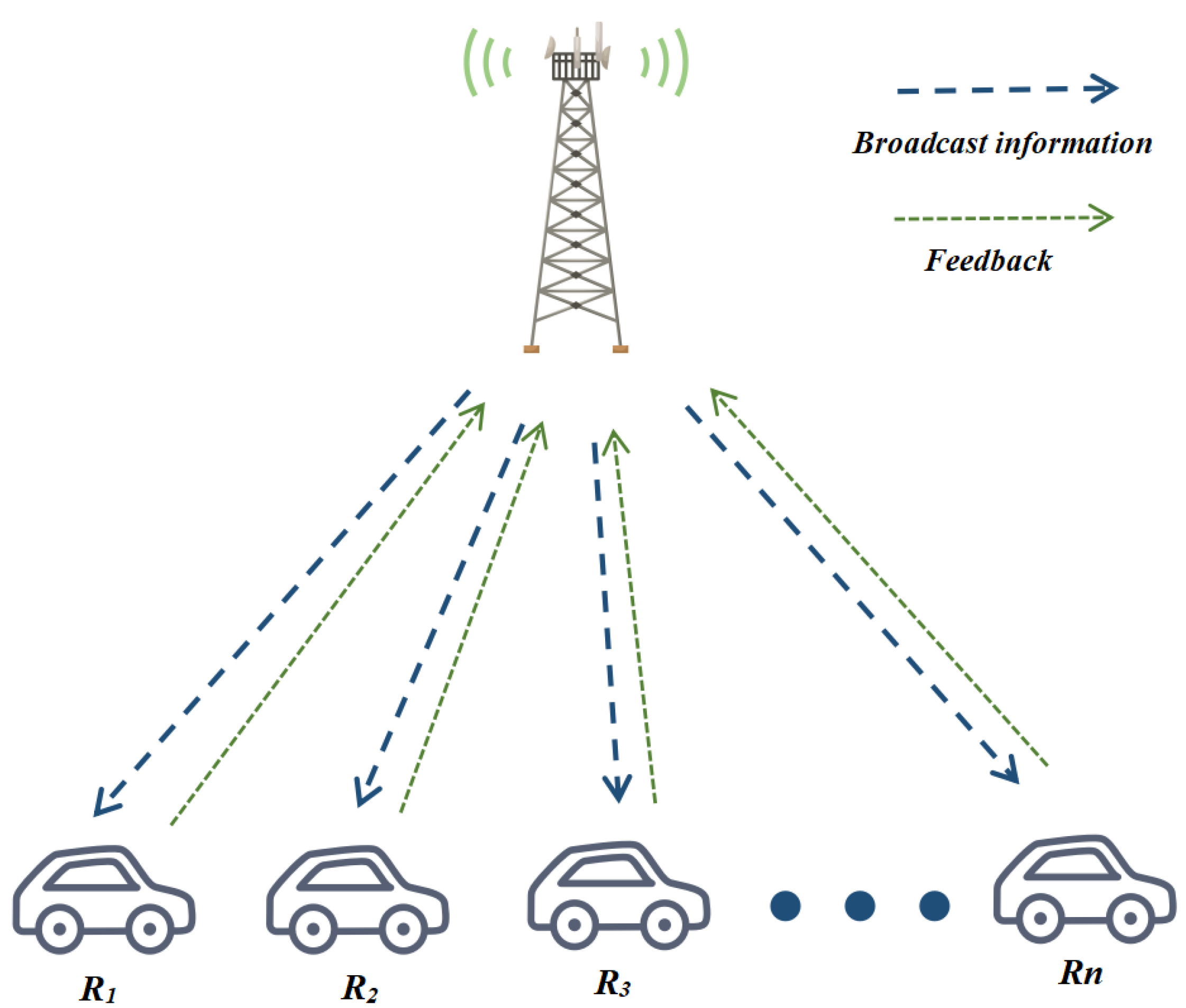
In the realm of V2X (Vehicle-to-Everything) communication, there is a compelling demand for highly reliable, short, and time-critical message broadcasting, originating from infrastructure or the vehicle, directed towards multiple nearby communication units. This need is especially pronounced within the contexts of V2V and I2V communication scenarios. In I2V communication, essential infrastructure components such as roadside units (RSUs), traffic lights, and sensors employ beacon broadcasting to disseminate safety-related information to nearby vehicles [
5]. In V2V communications, while multipoint-to-multipoint scenarios are more prevalent, point-to-multipoint communication instances are also prevalent. For instance, vehicles in distress transmit emergency safety information to alert nearby vehicles to potential hazards, thereby facilitating swift collision avoidance strategies [
6]. V2X broadcast communication encompasses the concurrent transmission of data packets, ensuring the efficient distribution of critical messages [
7]. Nevertheless, achieving efficient broadcast communication in V2X scenarios characterized by a short code length, low latency requirements, and high reliability remains a formidable challenge.
To address these challenges and improve the communication quality, various technical features have been introduced into V2X. The Automatic repeat request (ARQ) and Hybrid automatic repeat request (HARQ) are two widely known error control technologies employed to ensure reliable transmission [
8]. In ARQ, the receiver first performs error checking on the received packet. If it detects an error in the packet, it directly discards the packet and requests retransmission. The HARQ protocol, on the other hand, combines the advantages of both ARQ and the forward error correction (FEC) by incorporating information from previous transmission attempts of the same packet, enhancing the efficient utilization of communication resources [
9]. In [
10], a blind retransmission scheme based on HARQ is proposed to enhance the channel efficiency of the sidelink channel in the V2X environments. However, HARQ encounters challenges in broadcast scenarios where packets are transmitted from one source to multiple destinations with different channel conditions. Due to the need for ensuring correct reception for every packet, HARQ requires a large number of retransmissions, leading to a high latency and low transmission efficiency [
11].
Random linear network coding (RLNC) is a potent mechanism to achieve critical objectives in V2X broadcast communication with a low latency, elevated reliability, and efficient message distribution. RLNC accomplishes this by combining all original packets at the sender linearly, employing coefficients randomly selected from a finite field, thereby engendering encoded packets for transmission without necessitating feedback [
12]. In [
13], a novel medium access control (MAC) protocol, which integrates physical-layer network coding (PNC) with RLNC, is proposed to effectively improve the transmission efficiency and reliability of beacon broadcasting. The work in [
14] proposes a distributed network coding-based medium access control protocol (NC-MAC) to support the V2V beacon broadcast, and improves the broadcast reliability by combining HARQ and network coding. In [
15], RLNC is found to be able to effectively reduce latency in the multi-source single-sink V2V network with wireless broadcasting channels. However, it is essential to point out that the operations in RLNC are performed on the finite field of GF(q), which poses challenges in terms of computational complexity. Additionally, it is worth noting that RLNC does not require intricate coordination between nodes, which makes RLNC well-suited for networks with complex topologies. But, within the domain of I2V, an alternate landscape prevails, characterized by a preponderance of point-to-multipoint scenarios, in which RLNC may not perform well.
Fountain codes have emerged as an effective solution for achieving reliable transmission in broadcast scenarios [
16]. The concept of digital fountain codes, initially proposed in 1998, revolutionizes information transmission by allowing the encoder to continuously generate coded symbols and the receivers can successfully decode once the number of received coded symbols slightly exceeds the number of source symbols [
17]. The Luby Transform (LT) codes [
18] are the first full realization of the digital fountain concept, followed by raptor codes [
19]. R10 and RaptorQ codes are the two most successful and standardized raptor codes which can efficiently propagate data through a well-designed code structure combining a low-density parity-check (LDPC) and LT codes under broadcast networks [
20,
21]. However, in V2X scenarios, the short code length poses challenges as encoded symbols generated through random selection based on the degree distribution may not accurately meet the requirements of receivers, leading to a low transmission efficiency. An effective method to overcome these shortcomings is to combine fountain codes with feedback. By utilizing feedback to obtain receiver decoding status, the encoding strategy can be further improved. The Shift LT code in [
22] dynamically adjusts the degree distribution of the encoder to adapt to its decoding state according to the number of recovered symbols, which significantly reduces the overhead. In [
23], the online fountain code (OFC) that dynamically adjusts the encoding strategy based on feedback is constructed, which effectively reduces the number of encoded symbols at a lower decoding complexity. However, it is worth noting that the online fountain code scheme requires multiple feedback iterations and may have a low transmission efficiency in scenarios with limited feedback.
This paper proposes a raptor-like coded broadcasting (RLCB) scheme to facilitate effective reliable transmission with low complexity for short time-critical message broadcasting in V2X communication. In the RLCB scheme, we first propose a raptor-like encoding–decoding structure with a feedback retransmission mechanism, which can well adapt to the retransmission in broadcasting. On the basis of the raptor-like structure, we design a precoding matrix with a sufficient constraint relationship and reduced cycles, which can enhance the spectral efficiency. Then, we propose a phase-based encoding algorithm comprising systematic encoding, mutual exclusion-based network coding (MENC), and LT encoding with DRSD to effectively improve the transmission efficiency and reliability. Specifically, systematic encoding ensures our proposed RLCB is systematic. The well-designed MENC algorithm makes the encoded symbols instantly decodable, effectively spectral efficiency. The LT encoding with DRSD guarantees the reliability of the overall scheme by generating redundant symbols. Moreover, we perform the complexity analysis of the encoding and decoding process of our scheme. To validate our scheme, we conduct comprehensive numerical simulations in terms of the spectral efficiency, packet error rate (PER), and complexity, and analyze the performance gain brought by each component in the RLCB scheme. Numerical results show that the RLCB scheme outperforms R10 and HARQ in the broadcast scenario, achieving a maximum gain of 17% compared with R10 and 44% compared to HARQ in spectral efficiency. Additionally, the RLCB scheme boasts a lower PER than RaptorQ, while maintaining a comparatively lower complexity.
This paper is structured as follows. Firstly,
Section 2 presents the system model of V2X broadcast communication scenarios. Next, in
Section 3, we introduce the raptor-like coding structure, followed by the design of the precoding matrix and the MENC algorithm. The complexity analysis comparison of the proposed scheme and RaptorQ is provided in
Section 4. In
Section 5, we present the numerical results of HARQ, R10, RaptorQ, and the proposed schemes. Finally, the paper concludes with
Section 6.
3. Raptor-like Coded Broadcasting Scheme
3.1. Raptor-like Encoding and Decoding Structure
Figure 2 illustrates the encoding and decoding structure of the proposed scheme. The encoding process comprises padding, precoding, and phase-based encoding. During padding, the source symbols
of size
K are padded to
of size
with
symbols set to zero, where
and
H denote the number of rows of LDPC1 and LDPC2 submatrices in the precoding matrix, respectively. Note that the padded zeros represent the check result of the constraint relationships of LDPC1 and LDPC2. In the precoding operation, the padded symbols
go through the precoding matrix
to produce the intermediate symbols
of size
. The relationship between
and
can be expressed as
Then, the phase-based encoding is performed on intermediate symbols to generate the encoded symbols .
The transmission process includes one initial transmission and
r retransmissions. Considering the latency limitation, the maximum number of retransmissions is
. The phased-base encoding employs three main phases to generate the encoded symbols. The encoding phase is determined based on the transmission process: the initial transmission, retransmission, and last retransmission. In the initial transmission,
of the phased-base encoding performs systematic encoding by sending the source symbols directly. If there is no channel erasure happening in the initial transmission, the receiver will successfully receive the source symbols. Otherwise, the receiver provides feedback to request retransmissions. In the retransmissions,
of the phased-base encoding carries out MENC based on the feedback information. The MENC in
considers the mutually exclusive relationship between symbols and receivers; thus, the generated encoded symbols are instantly decodable and will certainly promote the decoding progress of each receiver. Furthermore, if the maximum number of retransmissions is reached and the decoding process is still unsuccessful, LT encoding with DRSD is used to generate additional redundant symbols in
[
24]. The redundant symbols generated in
can effectively cope with channel erasure and improve the reliability of the RLCB scheme.
In decoding, the received symbols
of size
N undergo a padding operation to extend them to
of size
, similar to the padding operation in the encoding process. Subsequently, the joint belief propagation-Gaussian elimination (BP-GE) decoding is performed on
based on the decoding matrix
to obtain the decoded intermediate symbols
. After decoding, the decoding matrix is reconstructed into an upper triangular matrix (of size
). The rows in the decoding matrix represent the symbols being decoded, and the columns represent the connection of the padded source symbol in the decoding. The symbols are viewed as not decoded when the corresponding row in the decoding matrix has one on the diagonal. As shown in
Figure 3, the receiver feeds back the column indices of zeros on the diagonal in the decoding matrix, which refer to the source symbols that are needed for the current decoding. Due to the improved design of the precoding matrix structure, the first
K symbols of the intermediate symbols are the source symbols, so we only need to decode the intermediate symbols and extract the first
K symbols as the result of the decoding.
The structure of the joint BP-GE decoding comprises three main steps: BP decoding, matrix deletion, and GE decoding. Firstly, we construct the decoding matrix combining the received symbols, and perform BP decoding on the decoding matrix. If the BP decoding is successful, the decoding process is completed. Otherwise, find the row with the degree of one in the decoding matrix. These rows representing symbols that have already undergone BP decoding. The ones in these rows can be arranged on the diagonal, so the corresponding column degree value is also one. To reduce the complexity of the subsequent GE decoding, the identified rows and columns are removed, effectively reducing the matrix size. Finally, GE decoding is performed on the reduced matrix.
3.2. Design of Precoding Matrix
Figure 4 illustrates the structure of the precoding matrix
. As shown in
Figure 4, the precoding matrix is composed of the constraint matrix
and systematic matrix
. The systematic matrix
consists of a identity matrix
and a zero matrix. According to (
1), the relationship between
and
is
Thus, the structure of the systematic matrix makes the higher K intermediate symbols equal to the source symbols. The constraint matrix mainly contains two regular low density parity check matrices: and . The design of mainly considers two perspectives: reducing the precoding code rate and introducing more precoding constraints by modifying the degree distribution.
Before the specific design of
and
, we determine the optimal dimension of the precoding matrix. The code rate of the precoding is
. To counter the channel erasure, the code rate of the precoding must satisfy
. Therefore, the dimension of the precoding matrix should meet
To expand the constraint relationship of the precoding matrix, the size of the zero matrix at the top right of
should be minimized. Additionally, a larger precoding matrix dimension results in a higher decoding complexity. Hence, it is crucial to determine the optimal dimension of the precoding matrix, which is given by:
Having determined the optimal dimension of the precoding matrix, we can then obtain the optimal degree distribution of
by solving the linear programming problem as described in [
24]. According to (
1), we define the intermediate symbols
as bit nodes, and the padded source symbols
as check nodes. By defining the check and bit nodes and specifying their degree distributions, we can construct a Tanner graph representation that efficiently captures the dependencies between the symbols [
25]. Specifically, we set the degree distribution of check nodes as
and the degree distribution of bit nodes as
, where
and
represent the possible maximum degree value of the bit nodes and check nodes, respectively. Then, the coding rate during transmission is calculated as [
26]
As shown in (
5), in order to improve the transmission efficiency, we need to minimize
. Hence, the optimization problem for the check node degree distribution can be formulated as
where
denotes the limit on the number of connecting edges, and
represents the restriction on successful decoding under the BEC, as introduced in [
27].
For the bit nodes, it is necessary to make each bit node be constrained by the check node, which implies that the degree distribution of bit nodes should be uniform. However, given the specific structure of the precoding matrix, we can only achieve uniformity for the first
bit nodes. The uniform degree value of the bit nodes in
can be obtained by
Due to the limitation of the number of connecting edges, it may not be possible to achieve the exact uniform degree distribution for the bit nodes. Thus, we define an acceptable range for the degree value. The optimization problem for the degree distribution of bit nodes can be expressed as follows:
where
is the constraint on the number of connecting edges, and
is the constraint for the identity matrix and zero matrix on degree-one bit nodes in
. Note that both the optimization target and the constraints of the optimization problem in (6) and (8) present linear relationships. Therefore, the optimization problem in (6) and (8) are linear programming problems, and can be solved iteratively using the CVX Matlab package.
Next, we can further improve
by reducing the number of cycles with a girth of four in the tanner graph. This can be achieved by using the progressive edge-growth algorithm [
25], which adds edges to the tanner graph while maintaining the girth constraint. The algorithm selects the check node farthest from the current bit node when adding edges to the tanner graph corresponding to the precoding matrix. If there is more than one check node farthest from the current bit node, the algorithm selects the check node with the lowest degree to add edges to.
3.3. Mutual Exclusion-Based Network Coding
The design of MENC takes into account two crucial components: the state feedback matrix and the mutually exclusive set. Let us discuss these components in detail.
Firstly, we define the state feedback matrix
as follows:
Note that the state feedback matrix shows the symbol requirements of the receivers based on the feedback information. Notably, each row and column of the state feedback matrix corresponds to a receiver and a symbol, respectively. Based on the state feedback matrix , the sender can obtain the decoding condition of the receivers.
In MENC, the sender selects symbols based on the state feedback matrix. The selected symbols are encoded through the XOR operation. For receivers, the received symbols may have three states for decoding: redundant, instantly decodable, and non-instantly decodable [
28]. The received symbols are redundant when the source symbols involved in it are not required by the receiver. If a encoded symbol contains only one required symbol for a receiver, the receiver can decode the required symbol through the XOR operation for certain, and this encoded symbol is called immediately decodable. On the other hand, if a encoded symbol contains two or more required symbols for a receiver, the required symbols cannot be decoded directly by the receiver. Thus, the encoded symbol is called non-immediately decodable.
To avoid the appearance of non-instantly decodable symbols, the proposed scheme constructs the mutually exclusive set (MES) by investigating the mutually exclusive relationships between symbols and performs network coding based on the MES. According to the definition of non-immediately decodable symbols, there should not be two or more selected symbols in the symbol selection during encoding that are both required by a particular receiver. Therefore, for the receiver, the symbols they need are mutually exclusive. We define the receiver-perspective MES as the union of the symbols corresponding to zero in
i-th row of the state feedback matrix
, denoted by
. Further, for the required symbol, the union of the receiver-perspective MES of all receivers who require the symbol is the symbol-perspective MES, denoted by
The symbols in the symbol-perspective MES are exclusion symbols of each other. Based on the symbol-perspective MES, we can avoid potentially mutually exclusive symbol combinations during the symbol selection, making the resulting encoded symbols immediately decodable for all receivers.
The overall coding process of MENC is divided into four steps: initialization, MES construction, symbol selection, and symbol check.
- (1)
Initialization
In this step, the sender obtains the decoding status of each receiver according to the feedback provided by the receivers, and constructs a state feedback matrix . Then, the sender constructs several symbol sets for subsequent MES construction and symbol selection. The total unrecovered symbol set of size is constructed as the union of the column indices of zero in each row (corresponding to each receiver) of the state feedback matrix . This set represents the symbols that have not been successfully decoded by all receivers. Additionally, the worst receiver’s unrecovered symbol set of size is constructed as the union of the column index of zero in the row that contains the maximum number of zeros in the state feedback matrix . The worst receiver refers to the receiver with the highest number of unrecovered symbols. Thus, represents the largest receiver-perspective MES and should be encoded first. Based on and , the candidate symbol set as is derived as of size .
- (2)
MES construction
In this step, the sender first builds the receiver-perspective MES
based on the state feedback matrix
. Then, the symbol-perspective MES
of each candidate symbol is constructed according to (
10). Next, sort the symbol-perspective MES
in reverse order by size. Note that the symbol with a larger MES is more likely to be mutually exclusive with other symbols, so it needs to be preferentially involved in encoding.
- (3)
Symbol selection
After MES construction, the mutually exclusive relationship between symbols has been clarified, and we proceed to select symbols for encoding according to symbol-perspective MES. Firstly, the sender traverses each symbol in to initialize the encoded symbol set , where denotes the set of the symbol index involved in the i-th encoded symbol. Then, the sender compares with the symbols in the symbol-perspective MES of each candidate symbol in turn, and adds this candidate symbol to if is not in the symbol-perspective MES of the candidate symbol. Once the symbol selection process is complete, the sender performs an XOR operation on the symbols in to obtain the encoded symbols.
- (4)
Symbol check
After the symbol selection based on the symbol-perspective MES, there may still be some candidate symbols, which are heavily mutually exclusive with other symbols and do not participate in the encoding. So in this step, we check if there are any candidate symbols that are not encoded, and if so, send them directly.
The specific process of the MENC algorithm is presented in Algorithm 1.
| Algorithm 1 Mutual Exclusion-based Network Coding |
Step1: Initialization 1.1. Initialize the state feedback matrix . 1.2. Initialize and according to the state feedback matrix . 1.3. Initialize the candidate symbol set . Step2: MES Construction 2.1. Construct the receiver-perspective MES for each receiver . 2.2. Construct the symbol-perspective MES for each candidate symbol . 2.3. Sort the symbol-perspective MES in reverse order by their size. Step3: Symbol Selection 3.1. for 3.2. Set ; 3.3. for 3.4. if 3.5. Set ; 3.6. end if 3.7. end for 3.8. end for Step4: Symbol Check 4.1. Check if there are any candidate symbols that do not participate in encoding. If so, send them directly. |
5. Numerical Results
To ensure the effectiveness and reliability of our proposed scheme, we conducted numerical simulations and present the results in this section. In the simulations, we varied the number of source symbols K to be 16, 32, and 64, and the channel erasure probability to be 0.1, 0.2, and 0.3. We also set the maximum number of retransmissions to be three to account for the low latency broadcast scenario. In the proposed scheme, we set the number of LT redundant symbols, denoted as , to be four.
It is important to note that complete recovery during transmission cannot be guaranteed due to the limitation imposed by the maximum number of retransmissions. Hence, we define the total number of unrecovered symbols of all receivers and transmitted symbols as
and
, respectively. To evaluate the proposed scheme, we measure its performance in terms of PER and spectral efficiency
, which are expressed as:
We compare the performance of the proposed scheme with that of other schemes in terms of PER and spectral efficiency. The results of the numerical simulations are presented in the following subsections.
5.1. Performance Comparison among R10, RaptorQ, RLCB and HARQ
In this subsection, the spectral efficiency and PER performance of the proposed RLCB scheme are simulated. For performance comparison, we also present the spectral efficiency and PER of R10 and RaptorQ. Note that RaptorQ is abbreviated as RQ in the legend of the figures. To fairly compare the performance of RLCB, HARQ is set for comparison as a traditional transmission scheme in broadcast scenarios.
Figure 5 shows the spectral efficiency versus the number of receivers
n where
(
Figure 5a),
(
Figure 5b), and
(
Figure 5c). From
Figure 5, we can see that the spectral efficiency of our proposed RLCB is between R10 and RaptorQ at different
K and
n values. Particularly, when
, the spectral efficiency of our RLCB scheme is comparable to that of RaptorQ and achieves a maximum gain of
compared to R10. This demonstrates the efficiency of our scheme in unicast scenarios. As a traditional transmission scheme, HARQ achieves good spectral efficiency in unicast scenarios
. However, as the number of receivers
n increases, the spectral efficiency of HARQ significantly deteriorates due to the need for a large number of retransmissions to ensure correct symbol reception by multiple receivers. In contrast, our proposed RLCB scheme, leveraging the advantages of a raptor-like structure and feedback mechanisms, achieves better spectral efficiency in broadcast scenarios. The combined analysis of
Figure 5a–c provides insights into how the spectral efficiency of RLCB, R10, RaptorQ, and HARQ varies with different values of
K. Interestingly, the gap in spectral efficiency between fountain codes (RLCB, R10, and RaptorQ) and HARQ gradually widens with an increasing
K. With longer code lengths, fountain codes can generate a larger number of unique encoded symbols and offer a larger symbol space. This increases the symbol diversity and reduces the probability that symbols are mutually exclusive, leading to better performance.
Figure 6 shows the PER comparison of RLCB, R10, RaptorQ, and HARQ versus the number of receivers
n where
(
Figure 6a),
(
Figure 6b), and
(
Figure 6c). HARQ achieves a PER close to zero, but this comes at the cost of a poor spectral efficiency. In contrast, our proposed RLCB scheme significantly improves spectral efficiency while maintaining a low PER below
under different conditions. Focusing on the comparison among fountain codes, we observe that RLCB outperforms R10 and RaptorQ in terms of PER for different values of
K and
n. As the value of
K decreases, the gap in PER between RLCB and R10/RaptorQ gradually widens. For instance, when
and
, the PER of RLCB is one order of magnitude lower than that of R10 and RaptorQ. This demonstrates the superior PER performance of RLCB, particularly for shorter code lengths.
Figure 7 shows the spectral efficiency comparison versus the number of receivers
n when
and
, respectively. It is evident from
Figure 7 that the proposed RLCB scheme outperforms both R10 and HARQ in terms of the spectral efficiency across different values of
. With increasing
, the gap in spectral efficiency between fountain codes and HARQ diminishes. This can be attributed to the fact that HARQ combines and decodes packets through chase combining to obtain a time diversity gain [
31]. As a result, HARQ exhibits a decreased sensitivity to the channel erasure probability. Notably, in
Figure 7a, the RLCB scheme achieves a maximum gain of
compared to HARQ when
.
Figure 8 shows a corresponding PER performance under the same setting as
Figure 7. It can be observed that at low channel erasure probabilities, the PER performance of the RLCB scheme is better than that of R10 and RaptorQ. Particularly in
Figure 8a, the PER of RLCB is one order of magnitude lower than that of R10 and RaptorQ.
Overall, the RLCB scheme demonstrates a notable balance between spectral efficiency and PER performance. It consistently outperforms R10 in terms of both metrics. When compared to HARQ, the RLCB scheme achieves a superior spectral efficiency while maintaining a comparable PER performance in broadcast scenarios. Specially, it is worth noting that RaptorQ operates on GF(256), which brings excellent performance at the cost of complexity. Thus, RaptorQ can almost be regarded as an upper bound on the performance of fountain codes, while our proposed RLCB scheme can achieve even lower PER than RaptorQ, which is actually a very significant performance gain.
5.2. Performance Comparison of Components in RLCB
In this subsection, we further analyze the internal components of RLCB. The performance comparison of R10, RLNC, RLCB, and RLCB variant schemes at
,
are presented in
Table 2. First, we consider RLCB
, which refers to RLCB without the precoding. The absence of the precoding matrix significantly decreases the spectral efficiency of RLCB. The precoding matrix in RLCB provides crucial constraint relationships that concentrate the required symbol indexes in the higher part. This concentration increases overlap among the required symbols and reduces mutual exclusion in MENC, leading to an improved performance. Next, we analyze RLCB
, where we replace the improved precoding matrix with the original precoding matrix used in the R10 code [
21]. Comparing RLCB with RLCB
, we observe that the proposed precoding matrix enhances the spectral efficiency of RLCB. We further evaluate RLCB
, where no redundancy processing is performed during the last retransmission to resist channel erasure. As a result, the PER performance deteriorates significantly. In contrast, RLCB
involves sending the MENC encoded symbols again directly during the last retransmission. However, this scheme is heavily affected by channel erasure, resulting in a PER of only
. Furthermore, we introduce RLCB
, where we replace MENC with ONCMB (Opportunistic Network Coding based Multiple combination packets broadcast) [
32]. Comparing RLCB with RLCB
, we observe that RLCB outperforms RLCB
in both spectral efficiency and PER. This indicates that the RLCB scheme effectively addresses the mutual exclusion problem in multi-receiver encoding in broadcast scenarios. It is important to note that the RLCB scheme consistently outperforms R10 in all scenarios while the performance of variant schemes may be lower than that of R10 in certain cases. In summary, the RLCB scheme achieves a superior performance compared to R10 by leveraging LT redundant coding to enhance PER and incorporating an improved precoding matrix, cascade structure design, and mutually exclusive network coding to enhance spectral efficiency.
Furthermore, we present the simulation result of RLNC on GF(2). It can be seen that the RLNC scheme does not perform well in spectral efficiency. Specifically, the spectrum efficiency achieved by RLNC in unicast scenarios is limited to 0.579, whereas in comparison, R10 attains 0.627, and RLCB achieves 0.672. Although RLNC’s performance is relatively improved in the broadcast scenario, it still lags behind R10 and RLCB. This unsatisfactory performance of RLNC is, in fact, foreseeable, primarily due to its inherent characteristic of not relying on feedback and the simplistic nature of random encoding within the GF(2) domain, which fails to effectively meet the receivers’ requirements. In contrast, the RLCB enhances performance by incorporating feedback and implementing a well-designed encoding algorithm.
5.3. Quantitative Complexity Analysis
Table 3 presents the encoding complexity of the RLCB and RaptorQ scheme at different values of
K,
, and
n. It is evident from the table that the quantitative encoding complexity of RLCB and RaptorQ increases as
K,
, and
n increase. Note that a higher value of
leads to more erased symbols during transmission, necessitating the generation of additional encoded symbols. When it comes to
n, an increase in the number of receivers results in a larger worst receiver’s unrecovered symbol set
. Additionally, an increase in the number of receivers also increases the possibility of mutual exclusion between receivers, which significantly impacts the complexity of RLCB encoding. By comparing the encoding complexity of the RLCB and RaptorQ, we can see that the encoding complexity of RLCB is one order of magnitude lower than that of the RaptorQ scheme, primarily due to the introduction of GF(256) operations in RaptorQ. Moving on to decoding complexity,
Table 4 compares the quantitative decoding complexity of Joint BP-GE, GE, and ID at different values of
K. It is important to note that the decoding complexity has minimal dependence on the channel erasure probability
and the number of receivers
n. Similar to the encoding analysis, the ID decoding in RaptorQ is much more complex than the Joint BP-GE and GE decoding in the RLCB scheme. Moreover, it can be seen that the complexity of joint BP-GE is significantly reduced compared to GE. The complexity of the Joint BE-GE algorithm is one order of magnitude lower than GE and two orders of magnitude lower than ID decoding in RaptorQ. This is attributed to the fact that the joint BP-GE algorithm performs a large number of BP decoding, leaving only a small matrix that requires GE decoding. In summary, the RLCB scheme exhibits significantly lower encoding and decoding complexity compared to the RaptorQ scheme. Additionally, the proposed Joint BP-GE algorithm effectively reduces the decoding complexity compared to the GE algorithm.
6. Conclusions
In this paper, we proposed a coded broadcast scheme to achieve an efficient and reliable transmission in broadcast scenarios with limited feedback. In the proposed scheme, a Raptor-like encoding-decoding structure was first constructed to introduce feedback on the traditional fountain code structure. In order to further make full use of the feedback message, we designed a phase-based encoding scheme according to the transmission progress, including three phases: systematic encoding, MENC, and LT encoding. Additionally, we optimized the constraint relationship of the precoding matrix to improve its performance. Furthermore, we conducted a complexity analysis of the encoding and decoding process of our proposed scheme. Simulation results show that our proposed scheme outperforms the R10 code in terms of both PER and spectral efficiency in unicast or broadcast scenarios. For spectral efficiency, RLCB achieves a maximum gain of 17% compared with R10, and 44% compared with HARQ. In addition, the proposed scheme achieves a better PER performance than the RaptorQ code with a lower complexity.
The current solution we are researching is mainly for single-hop propagation networks in I2V scenarios. We have also found that multi-hop networks have broad applications in V2X, especially I2V and V2V. How to apply our solution to multi-hop networks will be a future focus of our research. In addition to addressing the technical intricacies of multi-hop communication, we also plan to explore collaborations with other advanced physical layer channel coding techniques, such as polar codes and LDPC codes. These synergistic efforts may help us to extend our scheme to a wider range of channels like AWGN.


 ,
, 


