Article

A 121 dB SNDR Zoom ADC Using Dynamic Amplifier and Asynchronous SAR Quantizer

1
Institute of Microelectronics of the Chinese Academy of Sciences, Beijing 100029, China
2
University of Chinese Academy of Sciences, Beijing 100049, China
*
Author to whom correspondence should be addressed.
Electronics 2023, 12(2), 313; https://doi.org/10.3390/electronics12020313
Submission received: 15 November 2022 / Revised: 28 December 2022 / Accepted: 5 January 2023 / Published: 7 January 2023
(This article belongs to the Section Circuit and Signal Processing)

Abstract

:
This paper presents a discrete-time zoom analog-to-digital converter (ADC) for low-bandwidth high-precision applications. It uses a coarse-conversion 5-bit asynchronous self-timed SAR ADC combined with a fine-conversion second-order delta-sigma modulator to efficiently obtain a high signal-to-noise distortion ratio (SNDR). An integrator circuit using a high-gain dynamic amplifier is proposed to achieve higher SNDR. The dynamic amplifier uses a switched tail current source to operate periodically, simplifying the common-mode feedback circuit, reducing unnecessary static current, and improving the PVT robustness. Dynamic error correction techniques, such as redundancy, chopping, and dynamic element matching (DEM) are used to achieve low offset and high linearity. And a 2-bit asynchronous SAR quantizer with an embedded feed-forward adder is used in the second-order delta-sigma modulator to reduce the quantization noise caused by redundancy, and further achieve higher energy efficiency. Simulation results show that the ADC achieves a peak SNDR of 121.1 dB in a 390 Hz bandwidth at a 200 kHz sampling clock while consuming only 170 μ W from a 2.5 V supply and the core area is 0.55 mm 2 . This results in a Schreier figure of merit (FoM) of 184.7 dB.

1. Introduction

High precision applications, such as industrial measurements, medical diagnostics, and IoT devices, which are often slowly changing signals, are placing increasingly stringent requirements on the energy efficiency and performance of high-precision analog-to-digital converter designs. Δ Σ ADCs, which achieve high signal-to-noise ratios through oversampling and noise shaping [1,2], are often preferred for high-precision applications. However, conventional architectures of Δ Σ ADCs meeting all these requirements often result in low energy efficiency or high power consumption of the ADC, making them unsuitable for battery-driven autonomous systems. MASH or multi-bit architectures can achieve high resolution, but still only moderate energy efficiency [1,3,4]. SAR ADCs can be very energy efficient [5,6,7,8], but they are limited to medium bandwidth and medium resolution, and it is difficult to achieve high-resolution without calibration.
In recent years, many hybrid ADCs [8,9,10,11,12] have been proposed to combine the advantages of different architectures to achieve an outstanding performance that cannot be achieved by a single architecture. Zoom ADC [11,12] is a hybrid ADC that combines SAR ADC and Δ Σ ADC to achieve high resolution and high energy efficiency. The zoom ADC uses a two-step structure to zoom the reference range of the Δ Σ ADC to a small range near the input signal through SAR ADC coarse conversion, and unlike conventional two-step ADCs [13,14], the fine converter of the zoom ADC does not digitize the residuals of the coarse converter, so the accuracy of the conversion depends entirely on the accuracy of the fine Δ Σ ADC. In addition, zooming relaxes the resolution requirement of the fine converter, which leads to shorter conversion times and smaller internal signal fluctuations, thus relaxing the requirement for amplifier swing rate in the integrator and reducing the power consumption of the fine Δ Σ modulator.
However, in order to make the whole system architecture efficient, the op-amps in the loop filter integrator must have high gain to avoid quantization noise leakage. Traditionally, they are implemented by high-gain OTAs with a cascaded structure [1,3]. However, they use static bias currents, and their common-mode feedback (CMFB) wastes a large amount of unnecessary static current in integrator circuits with time-varying operating conditions due to the long build-up time and the constant operation of the circuit. Inverter-based amplifiers [15] does not require bias circuits and have high energy efficiency, which makes them an attractive choice for integrators. However, the proposed topology does not provide the required DC gain and is susceptible to PVT variations. Moreover, zoom ADCs are usually designed to provide at least ±1 LSB redundancy [11,12,16,17] in coarse conversion results to relax the error requirements of coarse conversion SAR ADCs. In the case of 1-bit quantization Δ Σ , this means that the modulator DAC must span at least three SAR LSBS, which leads to a significant loss of signal-to-quantization noise ratio (SQNR).
In this paper, we propose a discrete-time (DT) zoom ADC architecture that mitigates the SQNR loss due to redundancy and achieves ultra-high SNDR with high energy efficiency, and propose a new integrator based on a dynamic amplifier. A folded input pair is used in the dynamic amplifier to improve input/output swing and linearity, and a cascaded output stage is used to increase the amplifier’s gain even further. The impact of the gain error on the high-precision ADC is mitigated.The modulator can now operate dynamically, saving a significant amount of power by eliminating unnecessary static current. By combining this technology with a low-swing zoom ADC architecture, it is possible to achieve both low power and high accuracy. We also use a 2-bit asynchronous SAR quantizer with an embedded feedforward adder in the fine conversion modulator, which can fully utilize the DAC voltage level of the modulator, reduce the quantization noise due to redundancy, improve the SQNR by 9.5dB, and reduce the oversampling rate (OSR). Compared with the traditional flash multi-bit quantizer, asynchronous SAR saves more area and power. The first stage integrator in the zoom ADC is chopped to reduce its offset and 1/f noise, and in addition we employ a dynamic element matching (DEM) algorithm to mitigate the mismatch between the sampling capacitor cells, thus further improving the zoom ADC performance. The proposed ADC achieves a peak SNDR of 121.1 dB in a 390 Hz bandwidth at a 200 kHz sampling clock while consuming only 170 μ W. This results in a Schreier figure of merit (FoM) of 184.7 dB.
The rest of the paper is organized as follows: Section 2 briefly describes the zoom ADC architecture and describes the selection of SAR ADCs and the effect of amplifier finite gain errors on the system. Section 3 discusses the implementation of the specific circuit. Simulation results are presented in Section 4. Finally, conclusions are given in Section 5.

2. Zoom ADC System Design

2.1. Zoom ADC Architecture

Figure 1 depicts the proposed system architecture. A coarse conversion asynchronous SAR ADC and a fine conversion two-order feedforward Δ Σ modulator are used in the proposed zoom ADC. The input signal is first quickly coarsely converted, and then the “zoom” operation allows the reference of the fine ADC to span exactly across the input signal, thus relaxing the requirement for fine ADC resolution and reducing the number of conversion cycles required. Zooming also reduces the swing of the loop filter input and relaxes the linearity and drive requirements of the Δ Σ integrator, resulting in increased energy efficiency.
Moreover, by this “zoom” operation, we can also enlarge the coefficients of the first stage integrator of the fine Δ Σ . For conventional Δ Σ ADC, the first stage coefficient is usually less than 1 to ensure the loop stability and avoid overloading the integrator [18]. In the ADC of this paper, we take the first stage coefficient to 1.55 by simulation. Due to the limitation of thermal noise, the sampling capacitance of the first stage is usually taken very large for high precision ADC, and by amplifying the coefficient of the first stage, the size of the integrator capacitance can be greatly reduced, thus reducing the load of the integrator op-amp and the area of the circuit.
The digital code K generated after coarse conversion of the input signal in Figure 1 will be combined with the fine-converted code stream through digital logic and then converted to an analog signal through a DAC capacitor array as the high and low references for the fine Δ Σ modulator, as:
V R E F P = ( K + 1 ) · V L S B S A R
V R E F N = K · V L S B S A R
where V R E F P and V R E F N are the Δ Σ modulator’s high and low references, respectively, and V L S B S A R = 2 · V R E F 2 N is the quantization step of the N-bit coarse conversion SAR.
It can be seen that since the reference voltage of the modulator is reduced by the SAR ADC from the full swing voltage 2 · V R E F to 1 2 N of the previous one, reducing the resolution requirement of the modulator. Moreover, the amplitude of the input signal of the modulator becomes very small after the difference, so a simple and energy-efficient amplifier structure can be used in the integrator.
However, due to noise, linearity, and offset, we cannot guarantee that the coarse conversion SAR is error-free during conversion, as shown in Figure 2a, where the reference of the Δ Σ modulator cannot span the input signal due to coarse quantization conversion error, resulting in integrator overload.
To correct errors in coarse conversions, we introduce redundancy factors in the digital logic part where coarse and fine conversions are combined. As shown in Figure 2b, the input reference range of the Δ Σ can be extended by using redundancy. Even with possible errors, the input signal is accurately within that reference range. After incorporating the redundancy factor, the reference is denoted as:
V R E F P = ( K + 1 + M ) · V L S B S A R
V R E F N = ( K M ) · V L S B S A R
where M is the redundancy factor needed to accommodate the non-ideal characteristics of the SAR ADC and ensure that the modulator remains in its stable operating range.
With the use of redundancy factors, even if the coarse conversion ADC is not perfectly linear or there is a mismatch between coarse and fine conversion levels, as long as the error in the SAR conversion is below M LSBs, we can ensure that the input signal is always within the stable input range of the modulator, reducing the requirement for coarse conversion ADC performance metrics. As shown in Figure 2c, with redundant operation, we can ensure that the reference can span the entire signal despite the error in K. Therefore, SAR ADC does not limit the overall accuracy of zoom ADC.The combination of redundancy factor and quantizer output stream is completed by digital code.
However, Δ Σ DAC will span 3 V L S B S A R , and this “redundancy” triples the quantization error of the modulator, reducing the SQNR by 9.5 dB compared to the case without redundancy. although this can be recovered by increasing the OSR, it is at the expense of power consumption.
To reduce the increase in quantization noise due to redundancy, we use a 2-bit SAR quantizer in the modulator quantizer section to take full advantage of the DAC level. This operation does not cause any change in the feedback DAC, and the dynamic element matching (DEM) scheme required to obtain high linearity remains unchanged. The resulting increase in SQNR results in a corresponding decrease in OSR, which in turn reduces both analog and digital power consumption, while the 2-bit asynchronous SAR quantizer uses only one comparator compared to the multi-bit flash quantizer, and can be combined with a feed-forward structured adder.

2.2. Maximum Input Frequency and Coarse Conversion Resolution

For the zoom ADC, the coarse conversion ADC works on a successive approximation principle that causes an N clock cycle delay in the update of the conversion result, which will result in a corresponding N clock cycle delay in the refresh of the resulting modulator reference voltage range. If the frequency of the input signal V i n is too high, the coarse ADC will not be able to update the reference range of the fine ADC fast enough, leading to an increase in distortion. In the following we analyze the maximum input frequency ( F i n m a x ) that the zoom ADC can handle for a full-scale input signal.
For a sinusoidal signal, the fastest change in waveform occurs at the intersection of the signal and the x-axis, where the slope of the sinusoidal signal is greatest. For a full swing sinusoidal signal V i n with frequency f i n within the supply voltage V R E F , the maximum change in voltage within the conversion time T of the N-bit SAR ADC is expressed as:
Δ V i n = V R E F · T · 2 π · f i n
According to Equations (3) and (4), the range of the zoom ADC stabilization input V z o o m can be expressed as:
Δ V z o o m = V R E F P V R E F N = ( 2 M + 1 ) · V R E F 2 N 1
Need to ensure that the input signal variation Δ V i n is less than the stable reference range Δ V z o o m , brought into the two Equations (5) and (6), the maximum input signal frequency F i n m a x is obtained as follows:
F i n m a x < ( 2 M + 1 ) · 1 2 π · 2 N 1 · T
From Equation (7), it can be seen that the input frequency of the signal is inversely proportional to the conversion time T and resolution N of the SAR ADC and proportional to the redundancy factor M which ensures that the integrator is not overloaded.
In [11], the coarse SAR adc and fine Δ Σ ADC are executed sequentially, and the N-bit SAR ADC takes N cycles to calculate and update the coarse code K. A DR of 119.8 dB is achieved for the pseudo-DC input signal. however, due to its sequential operation, its bandwidth is limited to only 12.5 Hz.
As a result, instead of the traditional N-cycle SAR ADC, we use an asynchronous SAR ADC for the coarse conversion. The asynchronous SAR ADC computes the N-bit output code in a fraction of a clock cycle and ensures that it is transferred to the feedback DAC capacitor and updates the fine ADC reference range within half a sampling clock cycle. This cycle-by-cycle update of the fine reference means that the input only needs to remain within the fine reference for the duration of one cycle, which increases the maximum tolerable input frequency in (7), as well as allowing the use of a smaller redundancy factor.
The resolution of the coarse conversion ADC also determines the output swing of the fine integrator. The output range of the fine Δ Σ modulator integrator can be reduced by increasing the resolution of the coarse conversion ADC. Since the amplifier implementing the integrator function in the loop filter must provide accurate settling accuracy for the integrated charge, this can be achieved with less current and thus consume less power if the loop filter output has a smaller swing. Therefore, it is necessary to keep the integrator output swing as low as possible to improve energy efficiency.
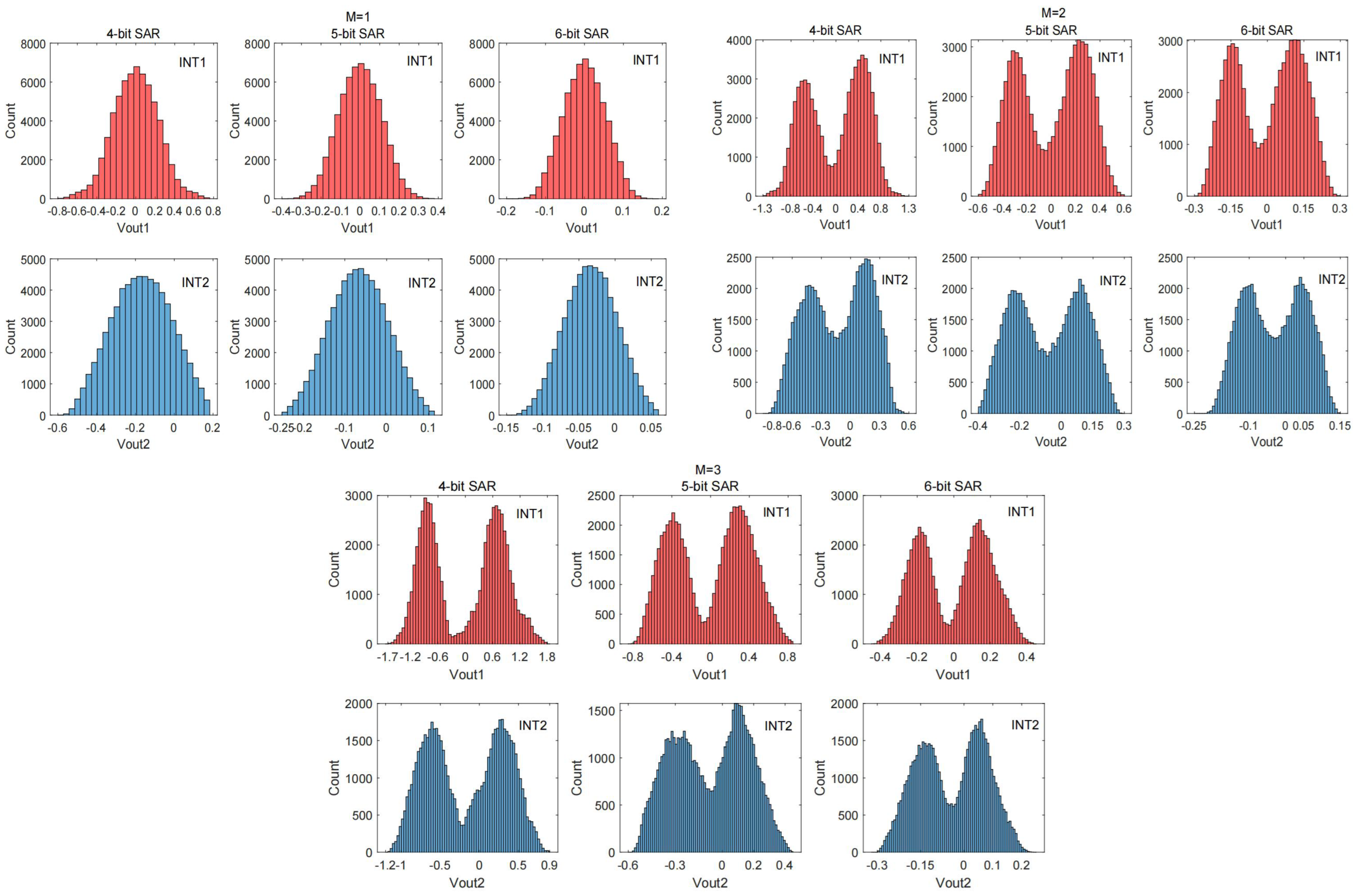
With the signal-to-quantization noise ratio (SQNR) required to satisfy the design, we simulated the effect of coarse conversion ADC on fine conversion ADC integrator swing for different bits of N = 4, 5, 6 and redundancy factors M = 1, 2, 3. As shown in Figure 3, it can be seen that when M = 1, the loop filter input swing for N = 4 is approximately twice that of N = 5, resulting in a proportional increase in loop filter power consumption to maintain linearity. While a loop filter with N = 6 achieves a lower swing, the maximum tolerable input frequency of the zoom ADC is reduced and the accuracy requirements of the SAR ADC increase, requiring an additional redundancy factor. It also leads to an increase in quantization noise in the zoom ADC and an increase in integrator output swing. Moreover, as the resolution of the coarse quantized ADC increases, the complexity of its feedback DAC capacitance increases exponentially. For these reasons, a coarse resolution of N = 5 and redundancy of M = 1 is used in this design to provide the best trade-off among power consumption, signal tracking capability, and complexity.

2.3. Amplifier Gain Error

The amplifier’s finite DC gain and gain variation is a significant source of error in high-precision zoom ADCs. Figure 4 depicts a typical implementation structure of an integrator in a modulator, and analysis of the structure yields the expression as:
C I [ V o u t ( n T + T ) + V o u t ( n T + T ) A ] = C I [ V o u t ( n T ) + V o u t ( n T ) A ] + C S [ V i n ( n T ) V o u t ( n T ) A ]
As a result, the z-domain transfer function expression is obtained as:
H ( z ) = V o u t ( z ) V i n ( z ) = C S C I [ A 1 + A + C S C I ] z 1 1 ( 1 + A ) ( 1 + A + C S C I ) z 1
According to the above equation, the gain error is A 1 + A + C S C I , and the pole position shifts from z = 1 to z p = ( 1 + A ) ( 1 + A + C S C I ) in the unit circle.
The gain error has only a small effect on the signal transfer function (STF), but a change in the pole position causes the same shift in the zero position of the noise transfer function (NTF). For a second order modulator, due to gain error can result in:
N T F = ( 1 z p 1 · z 1 ) ( 1 z p 2 · z 1 )
where z p 1 and z p 2 denote the change in the pole position of the second stage integrator of the first stage integrator, respectively. At DC ( z = 1 ), the NTF is not zero but equals to ( 1 z p 1 ) ( 1 z p 2 ) . Similarly, at low frequencies, changes in the noise transfer function due to finite gain can have a large impact on low-frequency noise shaping.
However, the gain of the op-amp is constant in this assumption. In practice, the gain of the op-amp varies with its input voltage, and this variation can also lead to distortion. The variation for the DC gain can be approximated by a third-order polynomial [19] as follows:
A ( V o u t ) = A d c · [ 1 δ ( V o u t V m a x ) ]
where A d c is the DC gain of fixed output, δ is the gain variation coefficient, usually taken as 0.9, which represents a significant third-order coefficient of variation, V o u t is the output swing, and V m a x is the maximum output swing.
Figure 5 depicts the modeling simulation of only the change in SQNR due to limited DC gain and amplifier gain variation in the zoom ADC integrator. It can be seen that a DC gain of 40 db causes a significant change in the noise transfer function (NTF) of the loop filter at low frequencies, which affects noise shaping and leads to a decrease in SQNR. To achieve the target SQNR of 130 dB (to allow a thermal noise-limited resolution of 20 bits) the DC gain of the amplifier must be at least 80 db or more for the effect of SQNR to be ignored. Although zoom type ADC can significantly reduce the integrator swing, considering the impact of op-amp gain on low-frequency high precision applications, we need to design a high gain and high linearity op-amp.

3. Circuit Implementation

The circuit schematic and timing diagram of the system is shown in Figure 6, which is composed of a 5-bit asynchronous SAR adc, a 2-bit SAR quantized two-order feed-forward Δ Σ modulator, and digital logic, where the redundancy factor is implemented by digital logic, and the specific details of the asynchronous SAR ADC circuit are shown in Section 3.2. Due to the better robustness of the switched capacitor (SC) circuit to voltage and process variations and clock jitter [20], a discrete-time (DT) modulator is used, where the switched-capacitor adder that implements the feedforward path is embedded in the SAR quantizer. We use bootstrap switches [21] in both coarse SAR ADC and Δ Σ modulator sampling switches to ensure the linearity of the circuit. The input sampling capacitor C S is also used as a feedback DAC capacitor array and consists of 31 unit capacitors C S j , which, along with the OSR, determines the zoom ADC’s thermal noise level.
During the circuit operation, the input is sampled using a fully differential sampling structure, and the sampling time of SAR ADC and Δ Σ is kept at half-clock cycle intervals to minimize the coupling between them. At φ 1 phase, the asynchronous SAR ADC tracks the input signal and at the end of the φ 1 phase, the SAR ADC completes signal sampling. The comparison of SAR ADC is triggered on the rising edge of φ 2 , because using an asynchronous clock, SAR ADC can complete the comparison and output the digital code K in a very short time. After that, the digital logic combines the digital code K and the integrator output code b s and converts them to 31 thermometer codes. After processing by the DWA algorithm, it passes to the 31 cell components of the feedback capacitor DAC to generate the appropriate feedback reference voltage.
The Δ Σ ADC tracks the input signal during the φ 2 phase while the first-stage integrator is chopped to suppress the first-stage amplifier’s offset and 1 f noise. At the end of φ 2 , the input is sampled to C S . And at the φ 1 phase, the first stage integrator performs integration while completing the subtraction of the feedback result from the input signal.
Since there is no residual calculation in the zoom ADC, its thermal noise level is determined by the noise of the fine ADC only. Considering the SNDR requirement and the limitation of thermal noise kt/c, the total sampling capacitance C S in this design is set to 8.9 pF, which is then subdivided into 31 unit capacitors and also used as the unit capacitance of the feedback DAC with a capacitance of 288 fF. The size of the first stage integrating capacitor C I 1 is 5.7 pF. With the help of noise shaping and the high gain of the first stage, the sampling capacitance C S 2 is relaxed to 188 fF and the integrating capacitor C I 2 is 564 fF. In addition, the offset and kt/c noise of OTA2 and SAR comparator are similarly relaxed.

3.1. Dynamic Amplifier

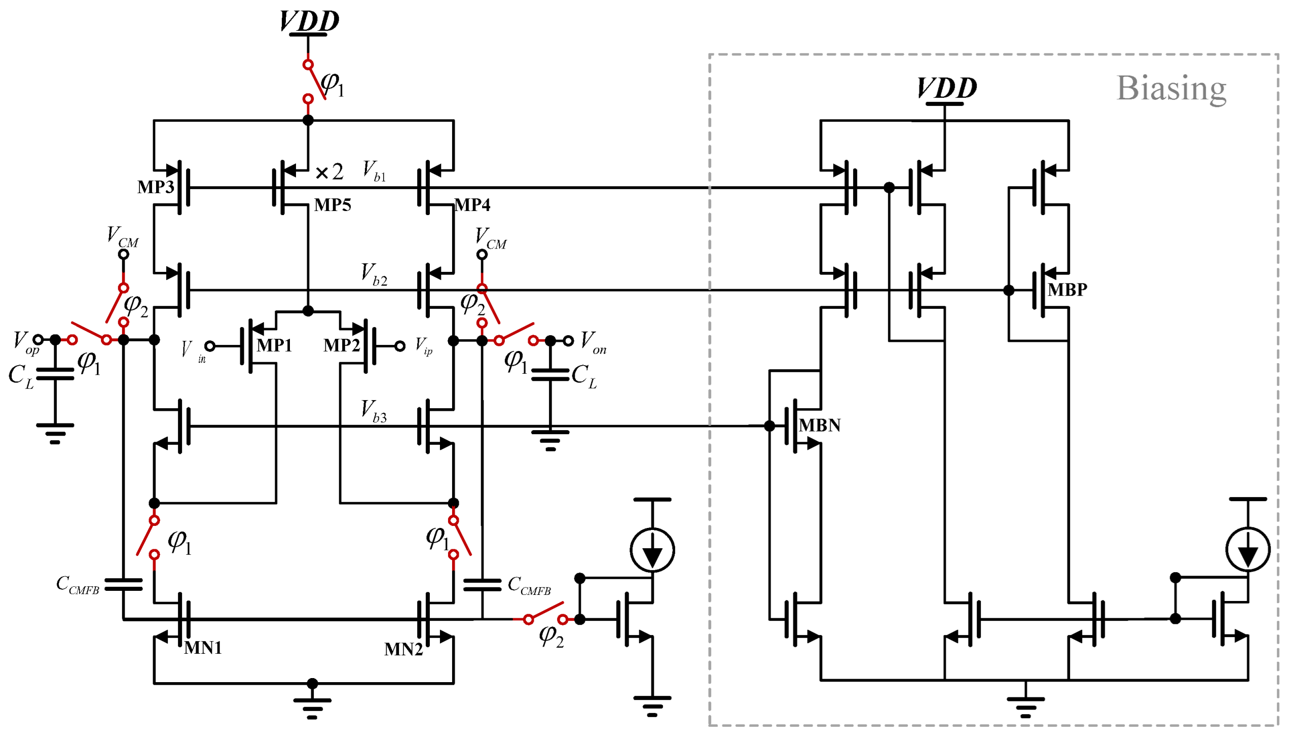
Figure 7 shows the schematic diagram of the proposed dynamic amplifier circuit. The dynamic amplifier employs a folded PMOS input pair transistor to improve the input/output swing and linearity. Compared with NMOS, PMOS has lower flicker noise and is suitable as an input stage, and a cascaded output stage is used to further improve the gain of the amplifier.
In contrast to previous dynamic amplifiers [18,22,23], we use a switched tail current source instead of directly using switches or capacitors. By providing a fixed tail current source when the amplifier is operating, firstly it helps to define the output CM voltage precisely, and secondly, this avoids the sensitivity of the transconductance to the input CM level. When the amplifier does not operate, the tail current source is turned off by a switch to reduce power consumption.
The circuits V b 1 and V b 2 and V b 3 are set by static bias circuits. The amplifiers described in [11,12] are dynamically biased, but require additional switches and bias voltage storage capacitors, resulting in a complex circuit structure and not very energy efficient. In this design, the folded structure of the dynamic amplifier relaxes the input-output swing requirements, and the coarse conversion ADC reduces the output swing of the amplifier, so we use a simple static bias circuit where the head and tail current sources MP3-4 and MN1-2 bias the 40 μ A current from a constant gm reference mirror when the switch is closed, thus suppressing the effects of supply voltage and temperature variations. Diode-connected transistors, MBP, are used to track threshold voltage changes and bias the amplifier cascade transistors to ensure that the entire circuit remains stable between PVT changes.
The second stage amplifier uses the same structure as the first stage, and because the high gain of the first stage amplifier relaxes the noise and linearity requirements, the second stage draws five times less current than the first stage, consuming only 8 μ A during operation. Both dynamic amplifiers use the same static bias circuit, which consumes only 4 μ A of current.
According to Figure 7, we can derive the small signal voltage gain of the dynamic amplifier. For simplicity, think of it as a single-pole system, the average values g m 1 , 2 and R o u t are used to model the transconductance and output resistances at different MOS drain voltages. The gain can be derived as:
G a i n = g m 1 , 2 R o u t ( 1 e t τ )
where τ = R o u t C L is the time constant of this single-pole system and R o u t ( g m N r O N 2 ) ( g m P r O P 2 ) is the output resistance of the entire circuit. For different amplification times, the gain of Equation (12) can be approximated in two different forms:
When t τ :
G a i n g m 1 , 2 C L t
And when t τ :
G a i n g m 1 , 2 R o u t
Equations (12)–(14) reveal the dynamic characteristics of the amplifier. Initially, the voltage gain varies linearly with (13), in accordance with the exponential law in (12), and eventually reaches the final value in (14). According to the condition in (14), it can be seen that when used for low-speed applications, the dynamic amplifier will show a voltage gain commensurate with that of a conventional amplifier. The difference is that the CM output voltage of the dynamic amplifier will vary instead of the constant value of the conventional amplifier. In fact, a dynamic amplifier can produce normal amplification as long as the value of the CM output voltage is not so low as to bring the transistor into the linear region.
As shown in Figure 8a, dynamic amplifier operation can be divided into two processes, the reset phase, and the amplification phase. In the reset phase ( φ 1 low, φ 2 high) the amplifier stops operating and the amplifier output is reset to the common-mode voltage V C M . And in the amplification phase ( φ 1 high, φ 2 low) the amplifier starts operating and charges the load capacitor C L at the output, after which the output voltage V o p / V o n will remain constant until the next reset phase starts.
Compared to the previous dynamic amplifier [18,22], as shown in Figure 8b. In the reset phase, the outputs are all pulled to V D D . In the amplification phase, the output voltage will start to drop from V D D towards V C M , and the amplifier is not working properly when it is not dropped to the V C M range, which severely limits the amplification time in the integration phase. In the proposed dynamic amplifier, the output voltage no longer drops rapidly from V D D to V C M , but operates directly from the common-mode voltage V C M , and the whole amplifier can enter the amplification state quickly, which allows the proposed amplifier to stabilize faster and the amplification time can be longer to achieve the amplified state shown in Equation (14).
As shown in Figure 9, the integrator switching logic using dynamic amplifiers differs from that of conventional integrators in that firstly. As shown in Figure 9a, in the first stage reset/sampling phase, the amplifier is reset off, one pole plate of C C M 1 and C C M 2 is connected to V C M and the other pole plate is connected to the gate of bias circuit transistor M B , and each capacitor voltage is charged to V C M V B by bias current; at the same time the output V o p , V o n are pulled to V C M . Although this reset operation clears the output voltage of the integrator, the charge information remains on the gates of amplifiers M P 1 and M P 2 and on the top plate of the integrator capacitor C I 1 due to charge conservation. Therefore, the periodic reset operation never destroys the integrated charge in C I 1 and C I 2 , ensuring proper integrator operation.
And in the first stage amplification/integration phase, as shown in Figure 9b, the dynamic amplifier starts amplification, and the φ 2 switch is opened. The output common-mode level generated at the output of the amplifier is equal to V C M V B + V G S N 1 , 2 , and we make the output common-mode level equal to V C M by ensuring that V B = V G S N 1 , 2 , which is very easy to achieve with the fixed tail current source provided in the dynamic amplifier. Also, during the amplification phase, the sampling capacitor of the second stage integrator is connected to the output of the first stage to sample the integration result of the first stage, while the second stage dynamic amplifier is in the reset phase. By operating the two amplifiers periodically, unnecessary quiescent currents are eliminated, resulting in a significant increase in integrator energy efficiency.
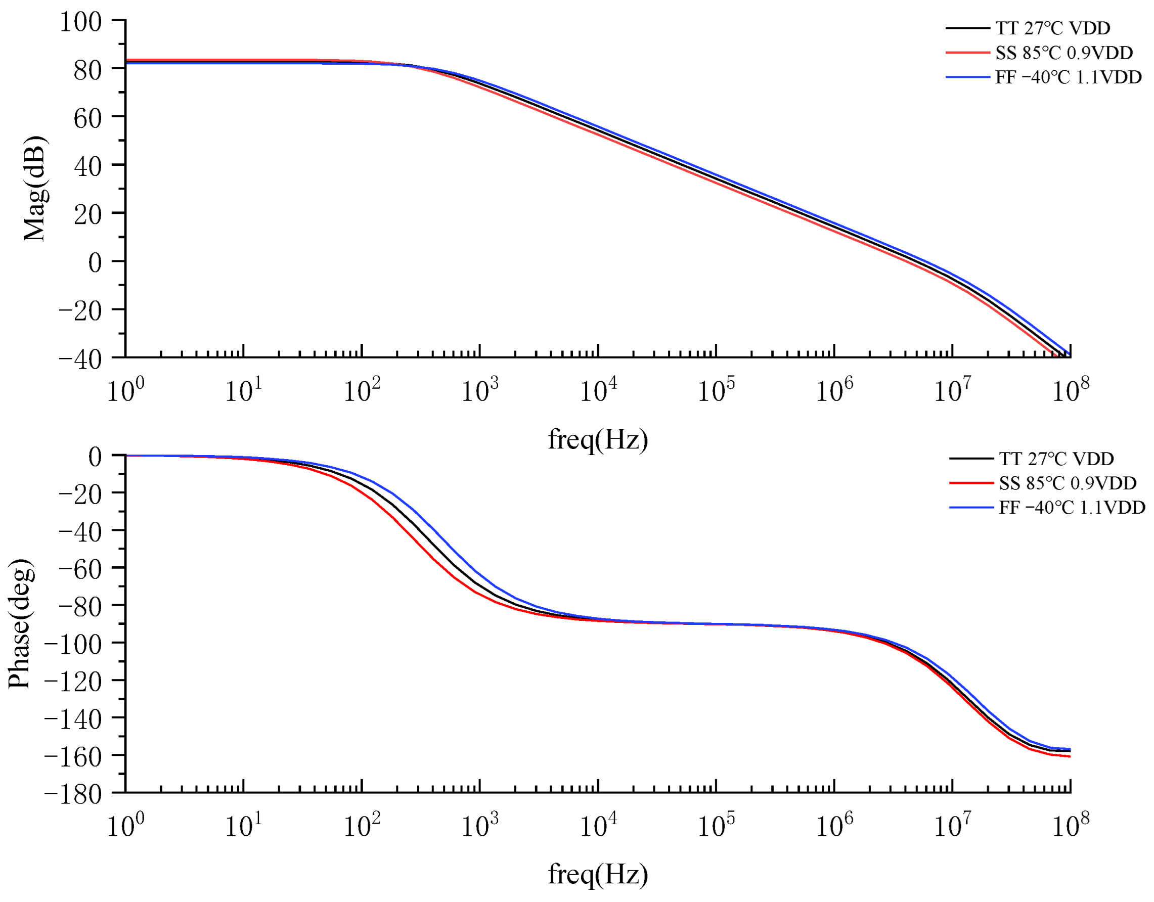
As shown in Equation (12)–(14), in a dynamic amplifier, the characteristics change with time. For this purpose, we simulated the variation of the DC gain and phase margin of the proposed amplifier for different PVT variations when the amplifier is operating stably during the integration process, as shown in Figure 10, where VDD = 2.5 V and the equivalent load capacitance size is 4 pF, the simulation results show that the DC gain of the amplifier can reach more than 80 dB under different PVT variations, and the unit gain bandwidth and phase margin can also remain stable.

3.2. Coarse Conversion Asynchronous SAR ADC

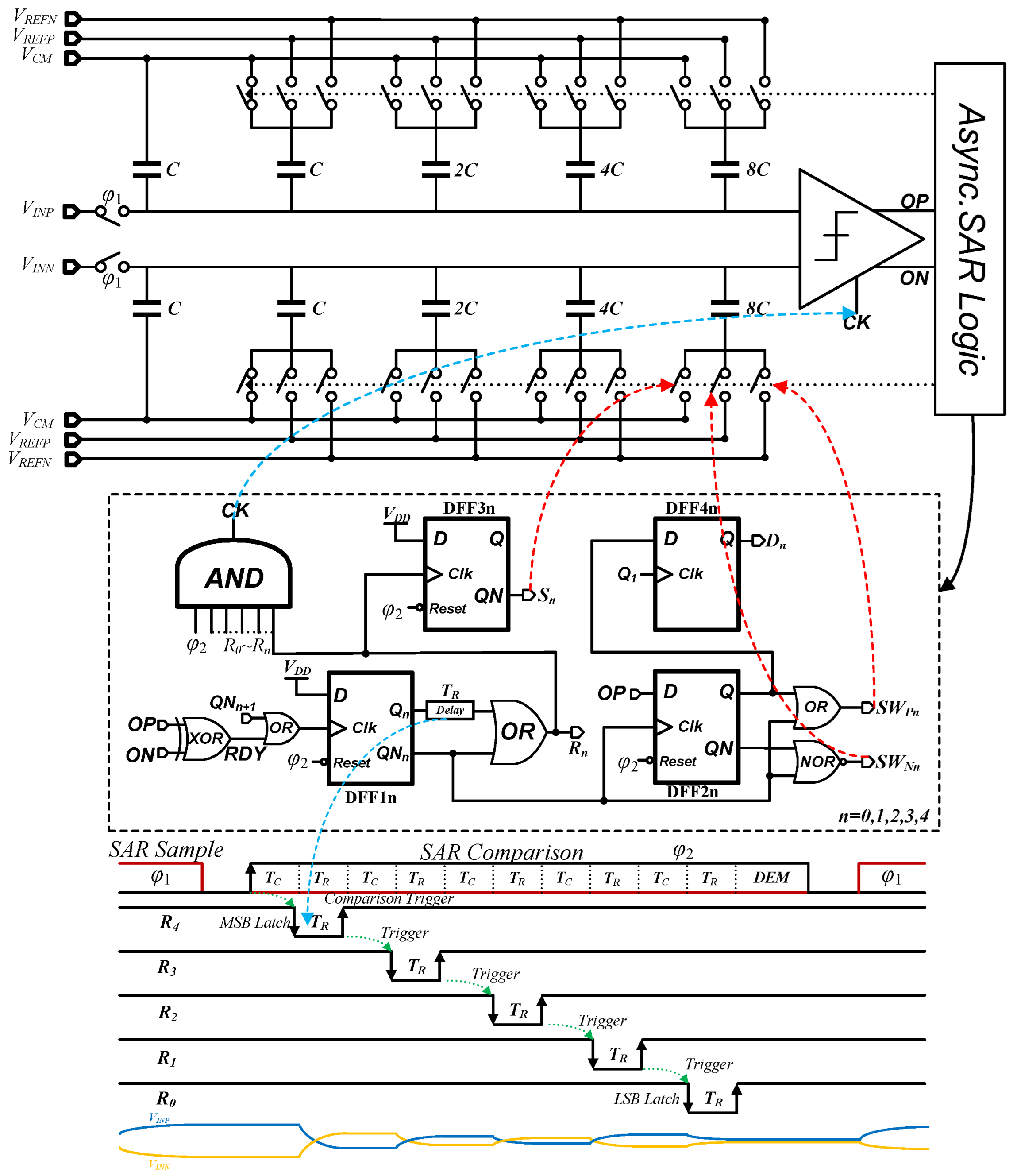
The method of updating the Δ Σ modulator reference for each clock cycle using asynchronous SAR improves the tracking capability of the signal and also relaxes the input swing of the integrator in the loop filter. In this paper, a modified asynchronous SAR ADC based on the VCM scheme, also known as the merged capacitor switch (MCS) scheme [24] is used with the circuit structure shown in Figure 11.
The switching scheme uses top plate sampling, so the signal is sampled in φ 1 cycle with the input connected to the top plate of the capacitor array and the bottom plate connected to the V C M voltage. The MSB is determined by comparison immediately after sampling without consuming any energy in the capacitor array. Further, ‘UP’ and ‘DOWN’ transitions are symmetrical and consume equal energy. Accordingly, we don’t need energy from V C M in each bit-cycling. Although the generation of the common mode voltage requires additional circuitry compared to the traditional switching scheme, in the zoom ADC we can share a V C M with the fine Δ Σ modulator, and the MCS scheme requires only half the capacitor array of the conventional switching scheme for the same accuracy.
The asynchronous logic uses self-timed control logic. The operation is triggered by the rising edge of φ 2 . These five comparisons of the asynchronous SAR ADC occupy only a small portion of the φ 2 cycle; the DEM and thermometer decoding will occupy the rest of φ 2 .
As mentioned in Section 2.1, the redundancy relaxes all the constraints of the SAR ADC such as noise, offset, and linearity. Since 1 V L S B S A R redundancy is used, the total SAR error should be limited to 1 V L S B S A R . the cell capacitor of the SAR DAC in the design is chosen to be 85 fF with more than 10 bits of accuracy. Because this design is mainly for low frequency and high precision applications, the circuit frequency is not high. The use of large capacitors in the coarse SAR ADC, compared to the resulting increase in power consumption, we think that smaller noise and higher linearity are more important. The asynchronous SAR ADC completes the conversion in less than 20 % of the zoom ADC sampling period (across PVT variations). To mitigate kickback noise due to fast asynchronous operation, a dynamic comparator with a constant current bias preamplifier is used [25]. The power consumption of the preamplifier is minimized by keeping it off during the signal sampling phase.

3.3. Feedforward Adder Embedded 2-Bit SAR Quantizer

Figure 12 shows the two operating modes of the 2-bit asynchronous SAR quantizer half equivalent circuit with embedded adder. In the sampling mode, the bottom plate of the sampling capacitor is connected to the input signals of V I N 1 and V I N 2 , respectively, and the top plate is connected to the V C M 1 signal, as shown in Figure 12a, then the total power stored on the capacitor q 1 can be expressed as:
q 1 = 2 C ( V I N 1 V C M 1 ) + 2 C ( V I N 2 V C M 1 )
In the summation mode shown in Figure 12b, the total capacitance between the input node V X P and V C M 1 of the comparator is 4 C when the bottom plate of the sampling capacitor is connected to V C M . The total charge on the capacitor q 2 is expressed as:
q 2 = 4 C ( V X P V C M 1 )
By the law of charge conservation, we have:
q 1 = q 2
Thus, it can be obtained that:
V X P = V I N 1 + V I N 2 2
Equation (18) indicates that the summation of two input signals can be achieved by the proposed capacitor array sampling technique. After the analog input summation is completed, the SAR conversion from MSB to LSB is the same as the asynchronous logic in Section 3.2. As mentioned above, the proposed SAR ADC implements not only a 2-bit quantizer but also a feed-forward adder, which saves power and area compared to the conventional multi-bit flash quantizer.

3.4. Dynamic Element Matching and Digital Logic

The DAC capacitor array of the zoom ADC is one of its most critical modules because it directly affects the total input reference noise and total harmonic distortion (THD) of the zoom ADC, and the mismatch between the cell capacitors is one of the main factors limiting the high SNDR of the zoom adc due to the fact that it generates data-dependent nonlinear errors and is not shaped by the loop filter in the same way as quantization errors. The target linearity of the feedback DAC capacitor array of the zoom ADC is achieved by using data-weighted averaging (DWA) [26], a well-known form of DEM that suppresses the ADC in-band noise power due to mismatch by first-order noise shaping. We can achieve an initial mismatch of 0.029% by Monte Carlo simulation using a 288 fF unit capacitor made from a MIM capacitor. However, we further improve the linearity of the DAC by using a data-weighted averaging (DWA) scheme. The worst-case residual error after DWA can be estimated as:
E < 1 O S R · 2 N 1 · δ m a x
where δ m a x is the worst-case mismatch value [11,12], OSR = 256, N = 5, and the worst-case mismatch according to Monte Carlo simulation is 0.029%. Therefore, a theoretical error level of 6 ppm is possible for the zoom ADC. This result meets our design requirements.
The digital logic adds redundancy to the digital code K of the asynchronous SAR and combines it with the code stream b s of the quantizer output to pre-compute the 5-bit output of the zoom ADC and convert it to a 31-bit thermometer code that is presented to the DAC switch after the DWA to generate the appropriate feedback voltage. Together, these two data blocks, the digital logic, and the DWA logic constitute the main source of energy consumption in the digital back end.

4. Simulation Results

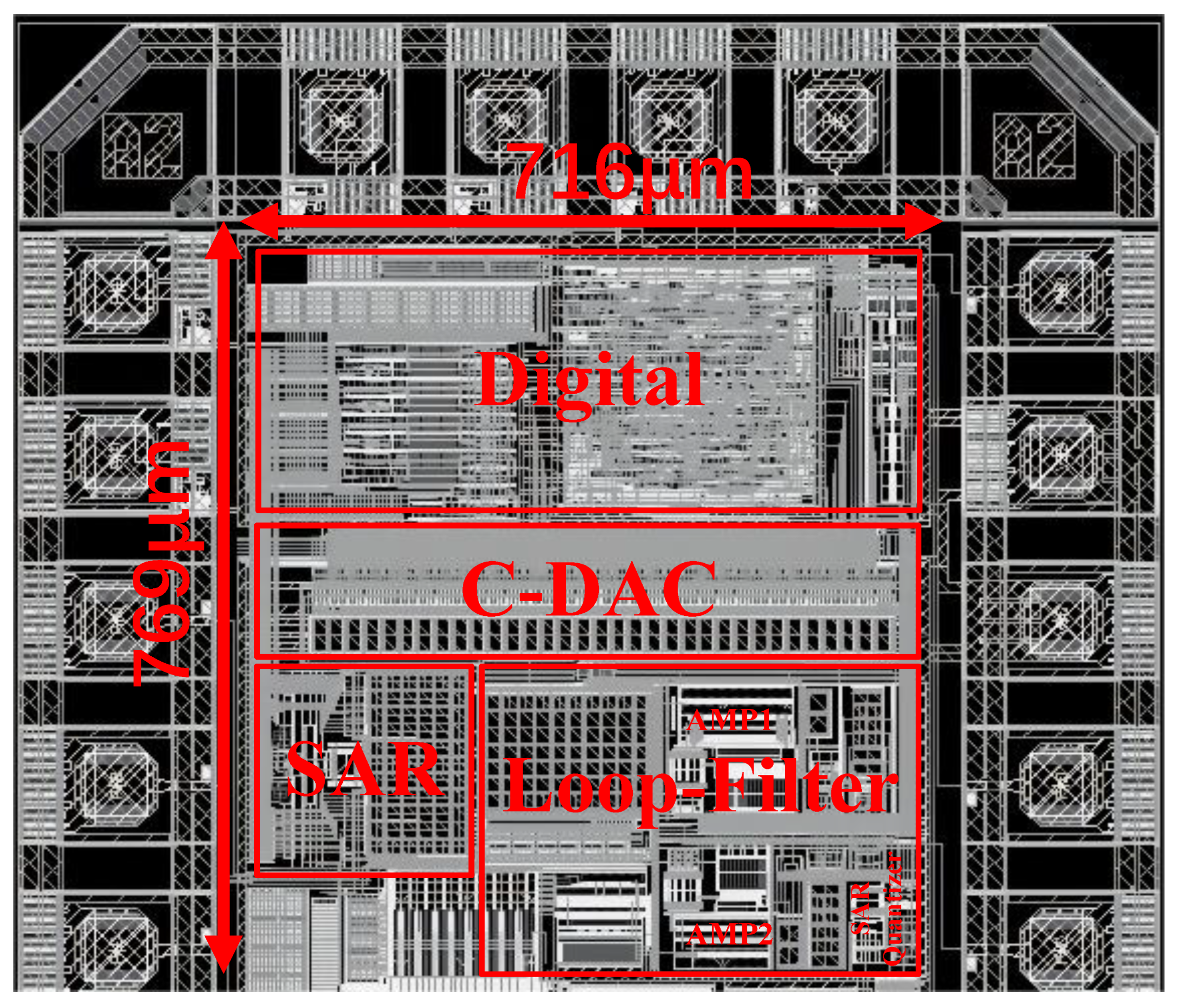
The proposed zoom ADC uses 0.35 μ m standard CMOS technology approach to complete the overall circuit layout design. The supply voltage is 2.5 V. Figure 13 shows the complete layout of zoom ADC, the active area of the zoom ADC is 769 μ m × 716 μ m. The implementation of different size capacitors in the layout uses multiple unit capacitor cells to achieve accurate coefficient matching. The unit capacitor is a high-density capacitor on a small chip area achieved using MIM capacitors. The layout was carefully designed to keep the analog portion of the zoom ADC symmetrically aligned, while also taking care to keep sensitive analog signals away from noisy digital signal paths.
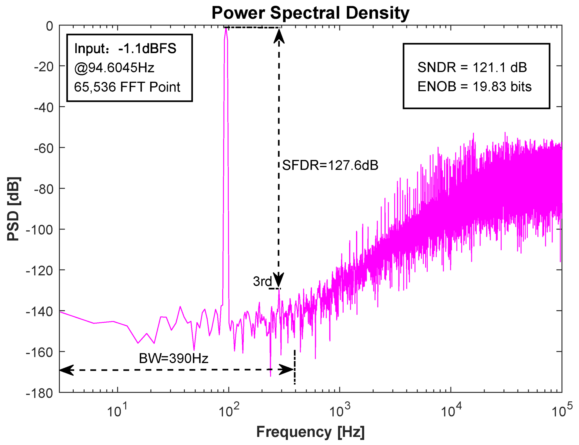
In all transient simulations, the transient noise option is enabled, and the effect of circuit noise is also considered. The simulations are performed in a typical process corner with a room temperature of 27 °C. Figure 14 shows the output power spectral density of the proposed ADC at a sampling rate of 200 kHZ. A sine wave input signal of 94.6045 Hz with an amplitude of −1.1 dBFS and an oversampling rate of 256 is used. The results show that the proposed zoom ADC architecture achieves 19.83 bits of ENOB and 121.1 dB of SNDR at an input frequency of 94.6045 Hz.
Figure 15 shows the SNDR versus input frequency for the simulation at a 200 kHz sampling rate. It can be seen that flat results are obtained in the bandwidth range of less than 390 Hz and the maximum SNDR variation is less than 3 dB. This frequency range basically covers the needs of most low-frequency and high-precision applications.
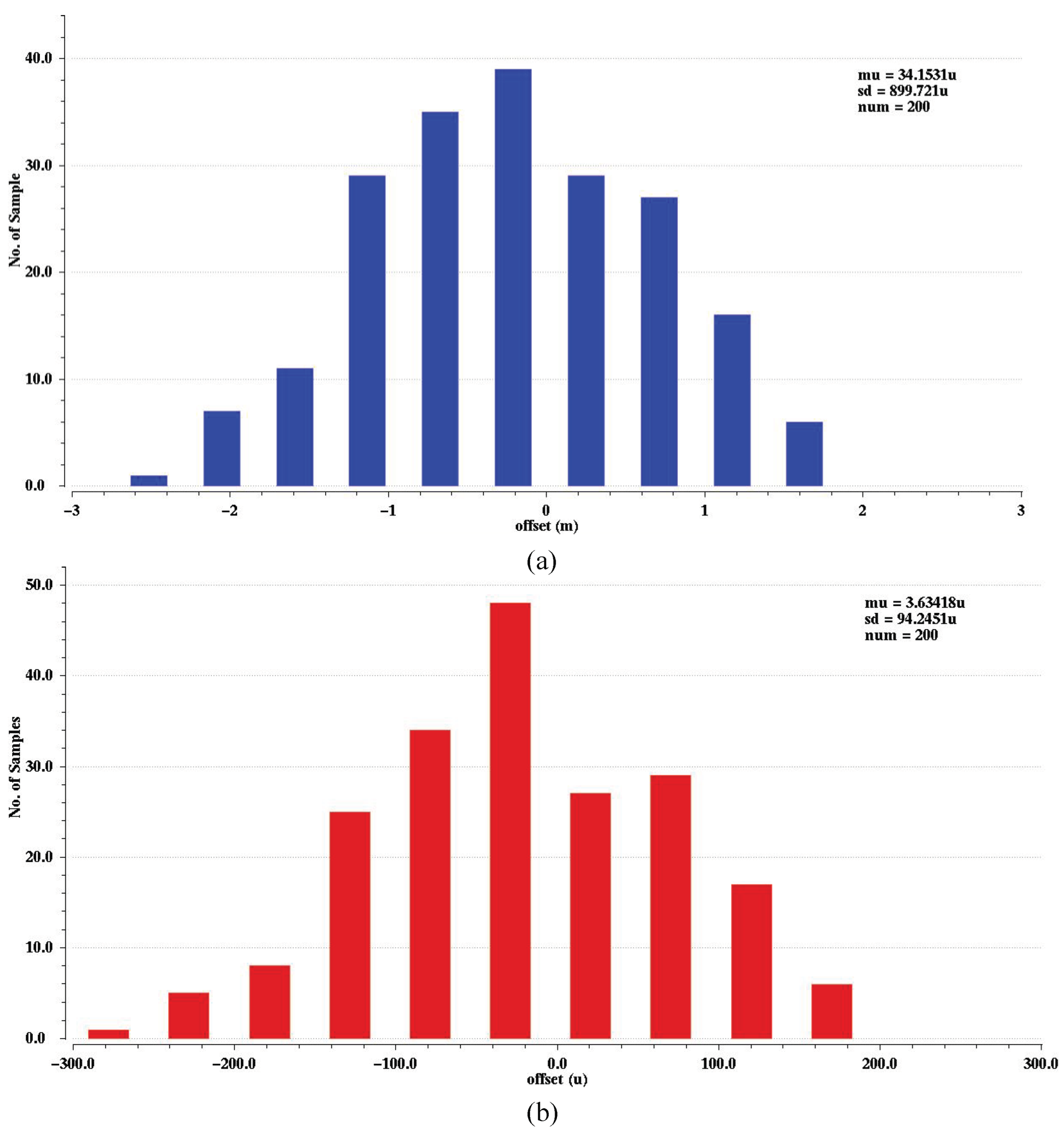
We also compared the offset of the first stage amplifier before and after chopping. As shown in Figure 16, after chopping, the offset mean value estimated over 200 Monte Carlo runs is 3.6 μ V, and the standard deviation σ is 94.2 μ V, demonstrating the effectiveness of chopper technology.
Table 1 summarizes the simulation results of different process corners, and variations of supply voltage and temperature (PVT) to verify the robustness of the proposed structure. It can be seen that zoom ADC obtains almost the same SNDR with different PVT characteristics.
The total power consumption is 170 μ W with a 2.5 V supply. Based on simulations, the ADC power breakdown is shown in Figure 17. Among them, the dynamic amplifier consumes 70 μ W of power, which can save more than 45% of power compared to the traditional static amplifier with the same structure, and the digital part (including asynchronous logic, DWA, and non-overlapping clock) consumes 62.5 μ W of power, and the CDAC consumes 25 μ W as a result of the noise-limited total capacitance.
Based on these results, the Schreier Figure of Merit (FoM) can be calculated as:
F o M S N D R = S N D R + 10 l o g 10 ( B W P o w e r ) = 184.7 dB
Table 2 summarizes the performance of the proposed ADC and compares it to other state-of-the-art hybrid architecture ADCs with similar resolution (SNDR > 96 dB). Compared to previous zoom ADCs [11,12], the ADC proposed in this paper achieves higher energy efficiency ( F o M S N D R ) at a lower oversampling rate, demonstrating the effectiveness of the technique used in this design. The ADC in [1] uses a lower oversampling rate to achieve a similar SNDR as the proposed ADC, but this comes at the cost of a higher order sigma-delta modulator and higher power consumption. The ADCs in [27,28] have lower power consumption, but they also have relatively low SNDR, and they are implemented with more advanced technology as well as lower supply voltages, resulting in significantly lower power consumption and area in the digital section.

5. Conclusions

This paper presents a zoom ADC that achieves ultra-high resolution and low power consumption. The combination of a fast 5-bit asynchronous SAR coarse conversion and a two-order sigma-delta modulator fine conversion achieves good energy efficiency and high resolution. In addition, a 1-bit redundancy factor is added to correct the errors caused in the SAR ADC during coarse conversion. To reduce the quantization noise increase caused by redundancy, we use a 2-bit SAR quantizer with an embedded passive feedforward adder in the modulator quantizer section instead of an active adder and quantizer to fully utilize the DAC level and reduce the quantization noise. An integrator circuit using a high-gain dynamic amplifier is proposed to extend the dynamic range of the modulator to achieve higher SNDR, and the periodic working of the dynamic amplifier further improves the energy efficiency of the ADC. Simulation results show that the proposed architecture is feasible to convert low bandwidth signals with high energy efficiency and high resolution.

Author Contributions

Conceptualization, Y.J., J.G., and G.G.; methodology, Y.J.; validation, J.G. and G.G.; formal analysis, Y.J.; investigation, Y.J.; data curation, Y.J.; writing—original draft preparation, Y.J.; writing—review and editing, Y.J., J.G., and G.G.; project administration, G.G. All authors have read and agreed to the published version of the manuscript.

Funding

This research received no external funding.

Data Availability Statement

No new data were created or analyzed in this study. Data sharing is not applicable to this paper.

Conflicts of Interest

The authors declare no conflict of interest.

References

  1. Ye, Y.; Liu, L.; Li, J.; Li, D.; Wang, Z. A 120 dB SNDR audio sigma-delta modulator with an asynchronous SAR quantizer. In Proceedings of the 2012 IEEE International Symposium on Circuits and Systems (ISCAS), Seoul, Republic of Korea, 20–23 May 2012; pp. 2357–2360. [Google Scholar] [CrossRef]
  2. Dorrer, L.; Kuttner, F.; Santner, A.; Kropf, C.; Hartig, T.; Torta, P.; Greco, P. A 2.2 mW, Continuous-Time Sigma-Delta ADC for Voice Coding with 95dB Dynamic Range in a 65 nm CMOS Process. In Proceedings of the 32nd European Solid-State Circuits Conference, Montreux, Switzerland, 19–21 September 2006; pp. 195–198. [Google Scholar] [CrossRef]
  3. Brewer, R.; Gorbold, J.; Hurrell, P.; Lyden, C.; Maurino, R.; Vickery, M. A 100 dB SNR 2.5 MS/s output data rate /spl Delta//spl Sigma/ ADC. In Proceedings of the ISSCC—2005 IEEE International Digest of Technical Papers. Solid-State Circuits Conference, San Francisco, CA, USA, 10 February 2005; Volume 1, pp. 172–591. [Google Scholar] [CrossRef]
  4. Gharbiya, A.; Johns, D.A. A 12-bit 3.125-MHz bandwidth 0–3 MASH delta-sigma modulator. In Proceedings of the ESSCIRC 2008—34th European Solid-State Circuits Conference, Edinburgh, UK, 15–19 September 2008; pp. 206–209. [Google Scholar] [CrossRef] [Green Version]
  5. Liu, J.; Li, D.; Zhong, Y.; Tang, X.; Sun, N. 27.1 A 250 kHz-BW 93 dB-SNDR 4th-Order Noise-Shaping SAR Using Capacitor Stacking and Dynamic Buffering. In Proceedings of the 2021 IEEE International Solid-State Circuits Conference (ISSCC), San Francisco, CA, USA, 13–22 February 2021; Volume 64, pp. 369–371. [Google Scholar] [CrossRef]
  6. Cao, Y.; Chen, Y.; Ni, Z.; Ye, F.; Ren, J. An 11b 80 MS/s SAR ADC with Speed-Enhanced SAR Logic and High-Linearity CDAC. In Proceedings of the 2018 IEEE Asia Pacific Conference on Circuits and Systems (APCCAS), Chengdu, China, 26–30 October 2018; pp. 18–21. [Google Scholar] [CrossRef]
  7. Liu, J.; Tang, X.; Zhao, W.; Shen, L.; Sun, N. A 13-bit 0.005-mm2 40-MS/s SAR ADC With kT/C Noise Cancellation. IEEE J. Solid-State Circuits 2020, 55, 3260–3270. [Google Scholar] [CrossRef]
  8. Xie, T.; Wang, T.H.; Liu, Z.; Li, S. An 84-dB-SNDR Low-OSR Fourth-Order Noise-Shaping SAR with an FIA-Assisted EF-CRFF Structure and Noise-Mitigated Push-Pull Buffer-in-Loop Technique. IEEE J. Solid-State Circuits 2022, 57, 3804–3815. [Google Scholar] [CrossRef]
  9. Zhang, Y.; Chen, C.H.; He, T.; Sobue, K.; Hamashita, K.; Temes, G.C. A two-capacitor SAR-assisted multi-step incremental ADC with a single amplifier achieving 96.6 dB SNDR over 1.2 kHz BW. In Proceedings of the 2017 IEEE Custom Integrated Circuits Conference (CICC), Austin, TX, USA, 30 April–3 May 2017; pp. 1–4. [Google Scholar] [CrossRef]
  10. Kim, K.; Oh, S.; Chae, H. Conception and Simulation of a 2-Then-1-Bit/Cycle Noise-Shaping SAR ADC. Electronics 2021, 10, 2545. [Google Scholar] [CrossRef]
  11. Chae, Y.; Souri, K.; Makinwa, K.A.A. A 6.3 µW 20 bit Incremental Zoom-ADC with 6 ppm INL and 1 µV Offset. IEEE J. Solid-State Circuits 2013, 48, 3019–3027. [Google Scholar] [CrossRef] [Green Version]
  12. Gönen, B.; Sebastiano, F.; Quan, R.; van Veldhoven, R.; Makinwa, K.A.A. A Dynamic Zoom ADC With 109-dB DR for Audio Applications. IEEE J. Solid-State Circuits 2017, 52, 1542–1550. [Google Scholar] [CrossRef] [Green Version]
  13. Agah, A.; Vleugels, K.; Griffin, P.B.; Ronaghi, M.; Plummer, J.D.; Wooley, B.A. A High-Resolution Low-Power Incremental ΣΔ ADC with Extended Range for Biosensor Arrays. IEEE J. Solid-State Circuits 2010, 45, 1099–1110. [Google Scholar] [CrossRef]
  14. Agah, A.; Vleugels, K.; Griffin, P.B.; Ronaghi, M.; Plummer, J.D.; Wooley, B.A. A High-Resolution Low-Power Oversampling ADC with Extended-Range for Bio-Sensor Arrays. In Proceedings of the 2007 IEEE Symposium on VLSI Circuits, Kyoto, Japan, 14–16 June 2007; pp. 244–245. [Google Scholar] [CrossRef]
  15. Chae, Y.; Han, G. Low Voltage, Low Power, Inverter-Based Switched-Capacitor Delta-Sigma Modulator. IEEE J. Solid-State Circuits 2009, 44, 458–472. [Google Scholar] [CrossRef]
  16. Karmakar, S.; Gönen, B.; Sebastiano, F.; van Veldhoven, R.; Makinwa, K.A.A. A 280 μ W Dynamic Zoom ADC with 120 dB DR and 118 dB SNDR in 1 kHz BW. IEEE J. Solid-State Circuits 2018, 53, 3497–3507. [Google Scholar] [CrossRef]
  17. Gönen, B.; Karmakar, S.; van Veldhoven, R.; Makinwa, K.A.A. A Continuous-Time Zoom ADC for Low-Power Audio Applications. IEEE J. Solid-State Circuits 2020, 55, 1023–1031. [Google Scholar] [CrossRef]
  18. Zhang, B.; Dou, R.; Liu, L.; Wu, N. A 91.2 dB SNDR 66.2 fJ/conv. dynamic amplifier based 24 kHz ΔΣ modulator. In Proceedings of the 2016 IEEE Asian Solid-State Circuits Conference (A-SSCC), Toyama, Japan, 7–9 November 2016; pp. 317–320. [Google Scholar] [CrossRef]
  19. Park, H.; Nam, K.; Su, D.K.; Vleugels, K.; Wooley, B.A. A 0.7-V 870-μ W Digital-Audio CMOS Sigma-Delta Modulator. IEEE J. Solid-State Circuits 2009, 44, 1078–1088. [Google Scholar] [CrossRef]
  20. Steiner, M.; Greer, N. 15.8 A 22.3 b 1 kHz 12.7 mW switched-capacitor ΔΣ modulator with stacked split-steering amplifiers. In Proceedings of the 2016 IEEE International Solid-State Circuits Conference (ISSCC), San Francisco, CA, USA, 31 January–4 February 2016; pp. 284–286. [Google Scholar] [CrossRef]
  21. Dessouky, M.; Kaiser, A. Very low-voltage digital-audio /spl Delta//spl Sigma/ modulator with 88-dB dynamic range using local switch bootstrapping. IEEE J. Solid-State Circuits 2001, 36, 349–355. [Google Scholar] [CrossRef]
  22. Chiang, S.h.W.; Sun, H.; Razavi, B. A 10-Bit 800-MHz 19-mW CMOS ADC. In Proceedings of the 2013 Symposium on VLSI Circuits, Kyoto, Japan, 12–14 June 2013; pp. C100–C101. [Google Scholar]
  23. van der Goes, F.; Ward, C.M.; Astgimath, S.; Yan, H.; Riley, J.; Zeng, Z.; Mulder, J.; Wang, S.; Bult, K. A 1.5 mW 68 dB SNDR 80 Ms/s 2 × Interleaved Pipelined SAR ADC in 28 nm CMOS. IEEE J. Solid-State Circuits 2014, 49, 2835–2845. [Google Scholar] [CrossRef]
  24. Hariprasath, V.; Guerber, J.; Lee, S.H.; Moon, U.K. Merged capacitor switching based SAR ADC with highest switching energy-efficiency. Electron. Lett. 2010, 46, 620–621. [Google Scholar] [CrossRef] [Green Version]
  25. Schinkel, D.; Mensink, E.; Klumperink, E.; van Tuijl, E.; Nauta, B. A Double-Tail Latch-Type Voltage Sense Amplifier with 18 ps Setup + Hold Time. In Proceedings of the 2007 IEEE International Solid-State Circuits Conference. Digest of Technical Papers, San Francisco, CA, USA, 11–15 February 2007; pp. 314–605. [Google Scholar] [CrossRef] [Green Version]
  26. Baird, R.; Fiez, T. Linearity enhancement of multibit /spl Delta//spl Sigma/ A/D and D/A converters using data weighted averaging. IEEE Trans. Circuits Syst. II Analog Digit. Signal Process. 1995, 42, 753–762. [Google Scholar] [CrossRef]
  27. Zhang, Y.; Chen, C.H.; He, T.; Temes, G.C. A 16 b Multi-Step Incremental Analog-to-Digital Converter with Single-Opamp Multi-Slope Extended Counting. IEEE J. Solid-State Circuits 2017, 52, 1066–1076. [Google Scholar] [CrossRef]
  28. Kuo, S.C.; Huang, J.S.; Huang, Y.C.; Kao, C.W.; Hsu, C.W.; Chen, C.H. A Multi-Step Incremental Analog-to-Digital Converter with a Single Opamp and Two-Capacitor SAR Extended Counting. IEEE Trans. Circuits Syst. I Regul. Pap. 2021, 68, 2890–2899. [Google Scholar] [CrossRef]
  29. Wang, B.; Sin, S.W.; U, S.P.; Maloberti, F.; Martins, R.P. A 550-μW 20-kHz BW 100.8-dB SNDR Linear-Exponential Multi-Bit Incremental ΣΔ ADC With 256 Clock Cycles in 65-nm CMOS. IEEE J. Solid-State Circuits 2019, 54, 1161–1172. [Google Scholar] [CrossRef]
Figure 1. Block diagram of the zoom ADC with 2-bit second-order loop filtering and a coarse asynchronous SAR.
Electronics 12 00313 g001
Figure 2. (a) Time domain waveform with coarse conversion error causing the input signal to be outside the reference range; (b) The coarse conversion result of the SAR ADC corresponds to the reference voltage range of the Δ Σ ADC; (c) Time domain waveform with input signal included in the reference range after redundancy.
Electronics 12 00313 g002
Figure 3. Output histogram of integrators INT1 and INT2 versus bits of coarse conversion ADC.
Electronics 12 00313 g003
Figure 4. Switched-capacitor integrator with finite-gain amplifier.
Electronics 12 00313 g004
Figure 5. Effect of amplifier’s DC gain and its nonlinearity on zoom ADC SQNR.
Electronics 12 00313 g005
Figure 6. Simplified circuit diagram of the proposed zoom ADC and the corresponding timing diagram.
Electronics 12 00313 g006
Figure 7. Schematic of a dynamic amplifier with bias circuit.
Electronics 12 00313 g007
Figure 8. (a) Proposed dynamic amplifier timing and output voltage variation. (b) The associated CM voltage drop effects proposed in [18,22].
Electronics 12 00313 g008
Figure 9. Working principle based on dynamic amplifier integrator: (a) sample/reset; (b) integrate/amplify.
Electronics 12 00313 g009
Figure 10. Gain and phase bode diagram of the amplifier in integrated/amplified phase.
Electronics 12 00313 g010
Figure 11. Schematic of 5-bit asynchronous SAR ADC and asynchronous logic, timing diagram.
Electronics 12 00313 g011
Figure 12. Equivalent circuit of SAR quantizer with embedded feedforward adder. (a) Sampling mode. (b) Summation mode.
Electronics 12 00313 g012
Figure 13. Layout of the proposed ADC.
Electronics 12 00313 g013
Figure 14. Simulated power spectral density (PSD) of the proposed ADC.
Electronics 12 00313 g014
Figure 15. SNDR versus input signal frequency at −1.1 dBFS input level.
Electronics 12 00313 g015
Figure 16. (a) Monte Carlo simulation of the first stage amplifier offset spread; (b) Monte Carlo simulation of the first stage amplifier offset spread after chopping.
Electronics 12 00313 g016
Figure 17. Power consumption breakdown.
Electronics 12 00313 g017
Table 1. PVT simulation results at −1.1 dBFS input level and F s = 200 kHz.
ParameterSS, 85 °C, 0.9 VDDTT, 27 °C, VDDFF, −40 °C, 1.1 VDD
SNDR (dB)120.4121.1121.6
ENOB (bit)19.7019.8319.90
Table 2. Performance comparison.
ParameterThis Work[11][12][1][27][29][28]
ArchitectureZoomZoomZoomMulti-bit Δ Σ IADC1IADC2IADC1
(SAR + Δ Σ + SAR)(SAR + Δ Σ )(SAR + Δ Σ )( Δ Σ + SAR)+Multi-Slope+Exp. Count+Binary Counting
Technology (nm)35016016018018065180
Area (mm 2 )0.550.3750.162.30.50.1340.27
Supply voltage (V)2.51.81.83.31.51.21.5
F s (MHz)0.20.025611.293.0720.64210.240.642
BW (kHz)0.390.012520241201.2
Power ( μ W)1706.3112020,00034.655033.2
OSR256102428264321256268
SNDR (dB)121.1119.810312096.8100.896.6
SFDR (dB)127.6125.2121111
F o M S N D R (dB)184.7182.7175.5180.8171.4176.4172.2
ResultSimulatedMeasuredMeasuredSimulatedMeasuredMeasuredMeasured
Disclaimer/Publisher’s Note: The statements, opinions and data contained in all publications are solely those of the individual author(s) and contributor(s) and not of MDPI and/or the editor(s). MDPI and/or the editor(s) disclaim responsibility for any injury to people or property resulting from any ideas, methods, instructions or products referred to in the content.