Article

A Novel Integrated UWB Sensing and 8-Element MIMO Communication Cognitive Radio Antenna System

1
Chaitanya Bharathi Institute of Technology, Hyderabad 500075, India
2
School of EEE, VIT Bhopal University, Bhopal 466114, India
3
Vaagdevi College of Engineering, Warangal 506005, India
4
Institute of Aeronautical Engineering, Hyderabad 500043, India
5
Department of Electronics & Communication Engineering, IMPS College of Engineering and Technology, Malda 732103, India
6
Department of Information and Communication Technology, Marwadi University, Rajkot 360003, India
7
Department of Information Technology, College of Computer and Information Sciences, Princess Nourah bint Abdulrahman University, P.O. Box 84428, Riyadh 11671, Saudi Arabia
8
Security Engineering Lab, Computer Science Department, Prince Sultan University, Riyadh 11586, Saudi Arabia
9
Department of Electronics and Electrical Communications Engineering, Faculty of Electronic Engineering, Menoufia University, Menouf 32952, Egypt
*
Author to whom correspondence should be addressed.
Electronics 2023, 12(2), 330; https://doi.org/10.3390/electronics12020330
Submission received: 22 November 2022 / Revised: 12 December 2022 / Accepted: 13 December 2022 / Published: 8 January 2023
(This article belongs to the Topic Antennas)

Abstract

:
In this article, a cognitive radio (CR) integrated antenna system, which has 1 sensing and 24 communication antennas, is proposed for better spectrum utilization efficiency. In the 24 communication antennas, 3 different operating band antennas are realized with an 8-element MIMO configuration. The sensing antenna linked to port 1 is able to sense the spectrum that ranges from 2 to 12 GHz, whereas the communication 8-element MIMO antennas linked with ports 2 to 9, ports 10 to 17 and ports 18 to 25 perform operations in the 2.17–4.74 GHz, 4.57–8.62 GHz and 8.62–12 GHz bands, respectively. Mutual coupling is found to be less than −12 dB between the antenna elements. Peak gain and radiation efficiency of the sensing antenna are better than 2.25 dBi and 82%, respectively, whereas the peak gains and radiation efficiencies of all communication antennas are more than 2.5 dBi and 90%, respectively. Moreover, diversity characteristics of the MIMO antenna are assessed by parameters such as DG, ECC and CCL. It is found that ECC and CCL are less than 0.42 and 0.46 bits/s/Hz, respectively, and also DG is more than 9.1 dB.

1. Introduction

In the licensed spectrum, channels are unutilized most of the time, thus leading to inefficient spectrum utilization. Hence, spectrum utilization efficiency deteriorates. The unutilized channels (i.e., licensed) can be used effectively for other applications to reduce the wastage of spectrum issue. CR technology mainly uses the concept of using the unutilized channels in the spectrum overlay approach. It is believed that the primary users in the spectrum overlay approach are the owners of the licensed spectrum and do not utilize their channels in the licensed spectrum completely. So, there exists a continuous monitoring in the radio environment to find the white spaces (i.e., spectrum holes). When a white space is detected at any moment, secondary users can use the channel that consists of the detected white space for other applications until the primary users want to use that channel. When primary users use that channel, secondary users should shift to any other unutilized licensed channels.
A new frequency-agile CR MIMO patch antenna was proposed in [1]. It comprises two patch antenna elements, which are hexagonal shaped. To achieve compactness and increase isolation, hexagonal-shaped defected ground structures are incorporated in the ground plane. The compactness is further attained by utilizing reactive loading. Varactor diodes are employed in the microstrip feed line to achieve frequency reconfigurability. Consequently, frequency tuning is achieved at 1.42–2.27 GHz. However, the proposed CR MIMO antenna cannot sense the spectrum as it does not have a sensing antenna. A frequency-reconfigurable CR MIMO antenna system for interweave scenario was presented in [2]. It comprises four reconfigurable antenna elements that are pentagonal slot-based. Varactor diodes are employed to alter the capacitance of the slot. As a result, a wide tuning range, which ranges from 3.2 GHz to 3.9 GHz, is achieved with a minimum of 100 MHz impedance bandwidth in each band. However, the proposed MIMO antenna does not have a sensing antenna. Additionally, the mutual coupling in the proposed CR MIMO antenna system is just less than −10 dB. A four-port CR MIMO antenna that works for overlay and underlay approaches for 5G applications in the 2.5–4.20 GHz range was proposed in [3]. This type of feature of the proposed antenna is obtained by controlling the operating modes of the multifunctional reconfigurable filter since the multifunctional reconfigurable filter, which works in three operational modes such as tunable bandpass filter, tunable band reject filter, and all pass filter, is integrated with UWB sensing antenna. Four filtennas are integrated on FR-4 epoxy substrate to make a MIMO system. Additionally, they are well isolated with the help of reflectors. A two element MIMO antenna, which comprises sensing antenna operating at 2.2–7 GHz and two similar reconfigurable antennas, was proposed in [4]. By varying the capacitance of varactor diodes, reconfigurable antennas can be tuned to any frequency from 2.3 to 6.3 GHz. A four-port MIMO antenna in which two antennas are dedicated for sensing the spectrum 2.35–5.9 GHz and two other antennas are dedicated for communication was proposed. The reconfigurable narrowband antennas for communication can be tuned to any frequency from 2.6 to 3.6 GHz.
The undesired radio frequency interference can be avoided when sensing antenna and communication antennas are well isolated. Consequently, good performance is guaranteed for a CR device. When spectrum holes change rapidly in the radio environment and a single reconfigurable antenna is used for sensing the spectrum and performing the communication tasks, it becomes very hard for the antenna to switch from sensing mode to communication mode and vice versa. Moreover, in case of reconfigurable antennas, loses become high due to the presence of lumped elements, diodes, etc. Consequently, the performance of the antenna deteriorates to some extent. Additionally, it is noticed that the existing CR MIMO antennas in the literature [5,6,7,8,9,10,11,12,13,14,15,16,17,18,19] have a small tuning range since it is quite hard to tune the antenna to a desired frequency in a wide bandwidth. The drawbacks, which are associated with the available reconfigurable CR antennas in the literature, are power consumption, use of extra hardware, nonlinear effects of switches and biasing line effects. Moreover, the reconfigurable mechanisms may require the presence of motors and some additional biasing circuitry at times. Nevertheless, they have been extensively used by many researchers to make the antenna compact and tunable. Additionally, they are very difficult to implement in real time. In addition, the available reconfigurable CR antennas in the literature are able to perform only communication operations despite multiple spectrum holes being identified. Since it is well known that low profile planar antennas are advantageous and reconfigurable antennas have some unavoidable drawbacks [20,21], integrated sensing antennas and multiple communication antenna systems [22,23,24,25,26] are treated as the best alternative to reconfigurable antenna systems for CR applications. These antenna systems have a striking feature of performing multiple communication operations simultaneously due to the presence of multiple communication antennas. Since the spectrum is utilized in an efficient manner by performing multiple communication operations simultaneously, spectrum utilization efficiency increases significantly with these antenna systems. Whenever a white space (spectrum hole) identified by the sensing antenna matches with the operating frequency of the communication antenna, the respective communication antenna is given access to the secondary users. Otherwise, it is terminated by a 50-ohm load. In integrated sensing antennas and multiple communication antenna systems, communication antennas are selected by an excitation switching reconfigurable mechanism.
In this article, a cognitive radio (CR) integrated antenna system, which has 1 sensing and 24 communication antennas, is proposed for better spectrum utilization efficiency. The sensing antenna linked to port 1 is able to sense the spectrum that ranges from 2 to 12 GHz, whereas the communication 8-element MIMO antennas linked with ports 2 to 9, ports 10 to 17 and ports 18 to 25 perform operations in the 2.17–4.74 GHz, 4.57–8.62 GHz and 8.62–12 GHz bands, respectively. Mutual coupling is less than −12 dB. The HFSS EM simulation tool is used for the proposed structure design. The fabricated prototype is verified and a good agreement is noted between the simulated and measured results. To the best of our knowledge, this is the only sensing and 8-element MIMO communication integrated antenna system that has the notable feature of performing a maximum of three communication operations concurrently in the CR environment. Moreover, this antenna system is the best alternative for all reconfigurable CR MIMO antenna systems. Additionally, it is less complex compared to all the other existing CR MIMO antennas in the literature.
The rest of the paper is organized as follows. The design of the proposed structure, UWB and narrow band antenna design steps, along with performance characteristics, are reported. Later, results and discussion on each and every performance parameter are provided. Thereafter, MIMO diversity characteristics are discussed. Finally, the conclusion of the work is given.

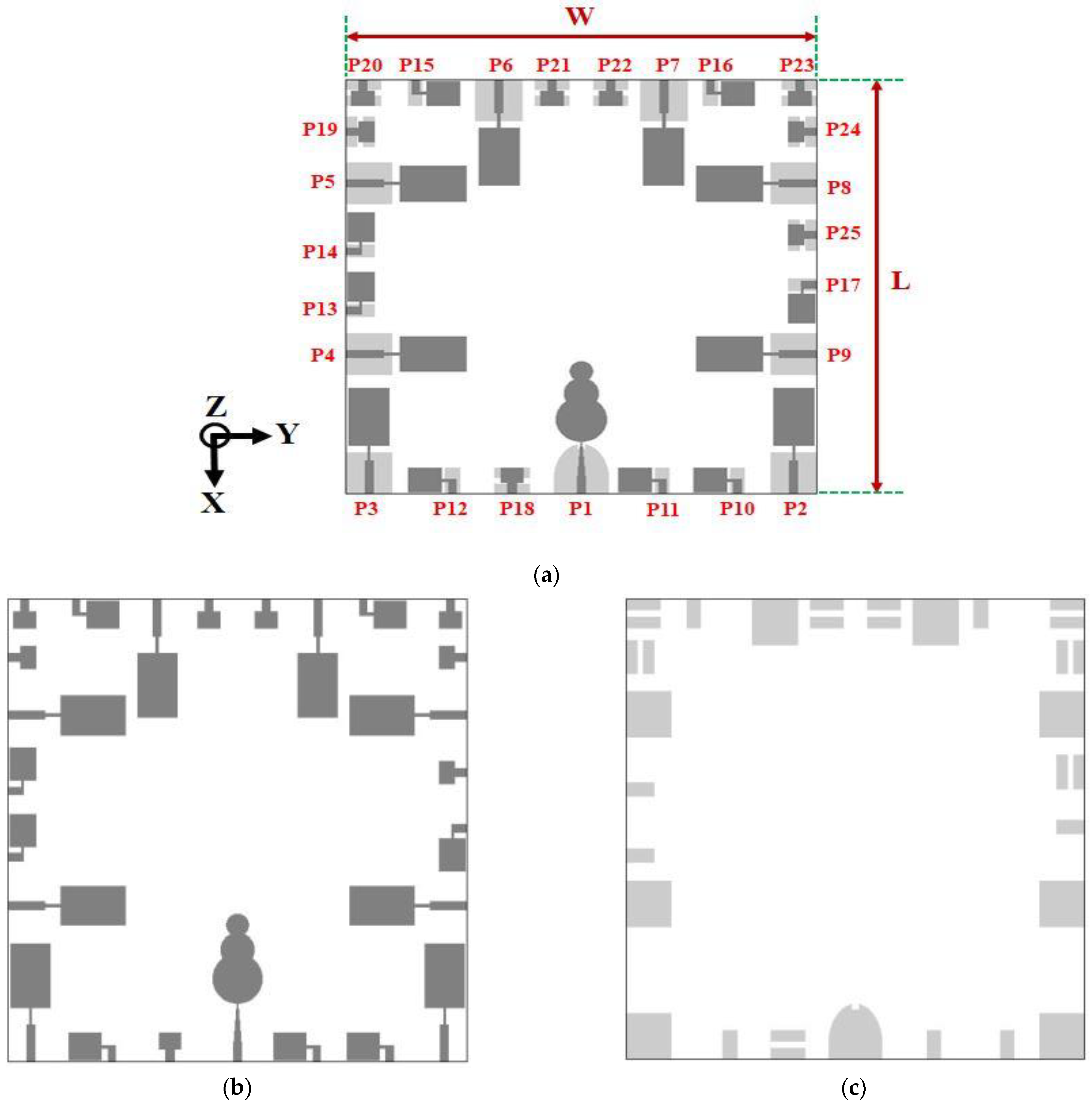
2. Twenty-Five Port CR Integrated Antenna System

The proposed CR integrated antenna system schematic is shown in Figure 1. The performance and 10 dB return loss bandwidth of each antenna are given in Table 1. The dimensions of the proposed CR integrated antenna system are given in Table 2. Sensing antenna is linked to port 1, whereas the communication 8-element MIMO antennas are linked with ports 2 to 9, ports 10 to 17 and ports 18 to 25. FR4 epoxy substrate of a thickness of 1.6 mm is used in the present design. Additionally, the design procedures for sensing and communication antennas are explained in this section.

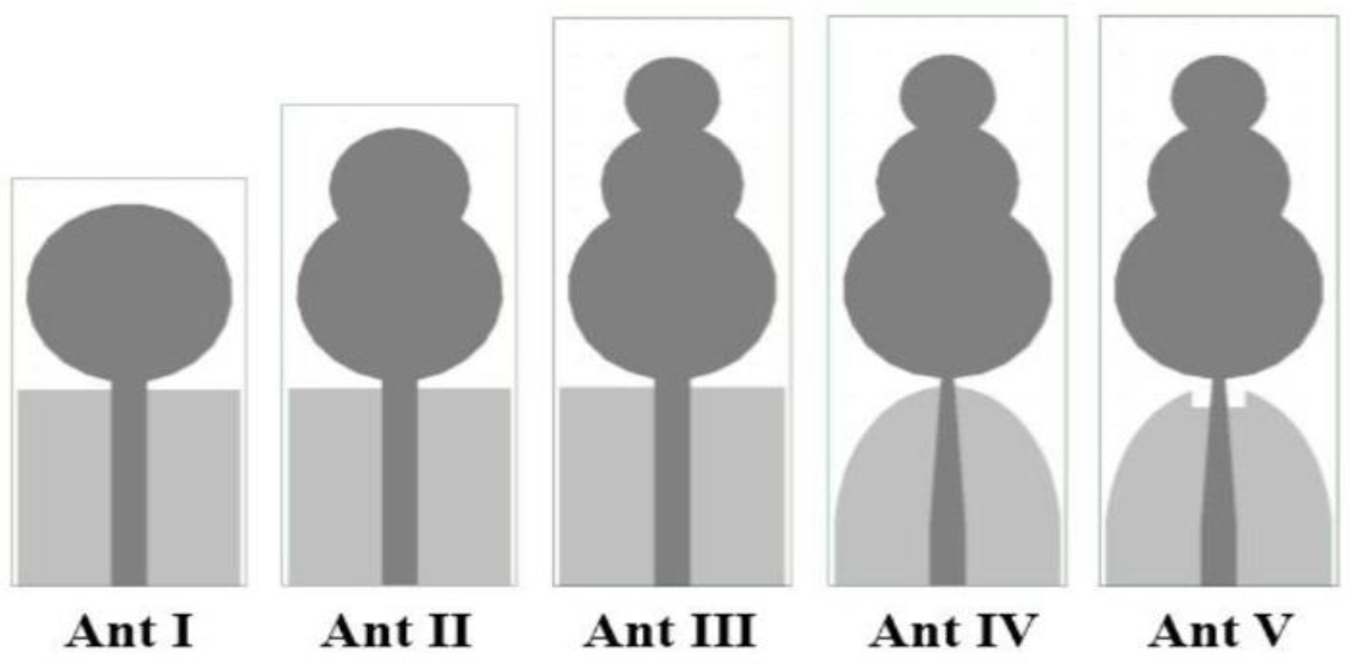
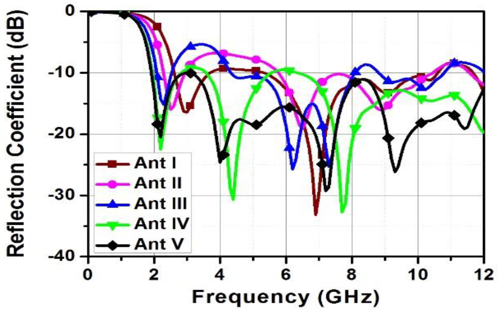
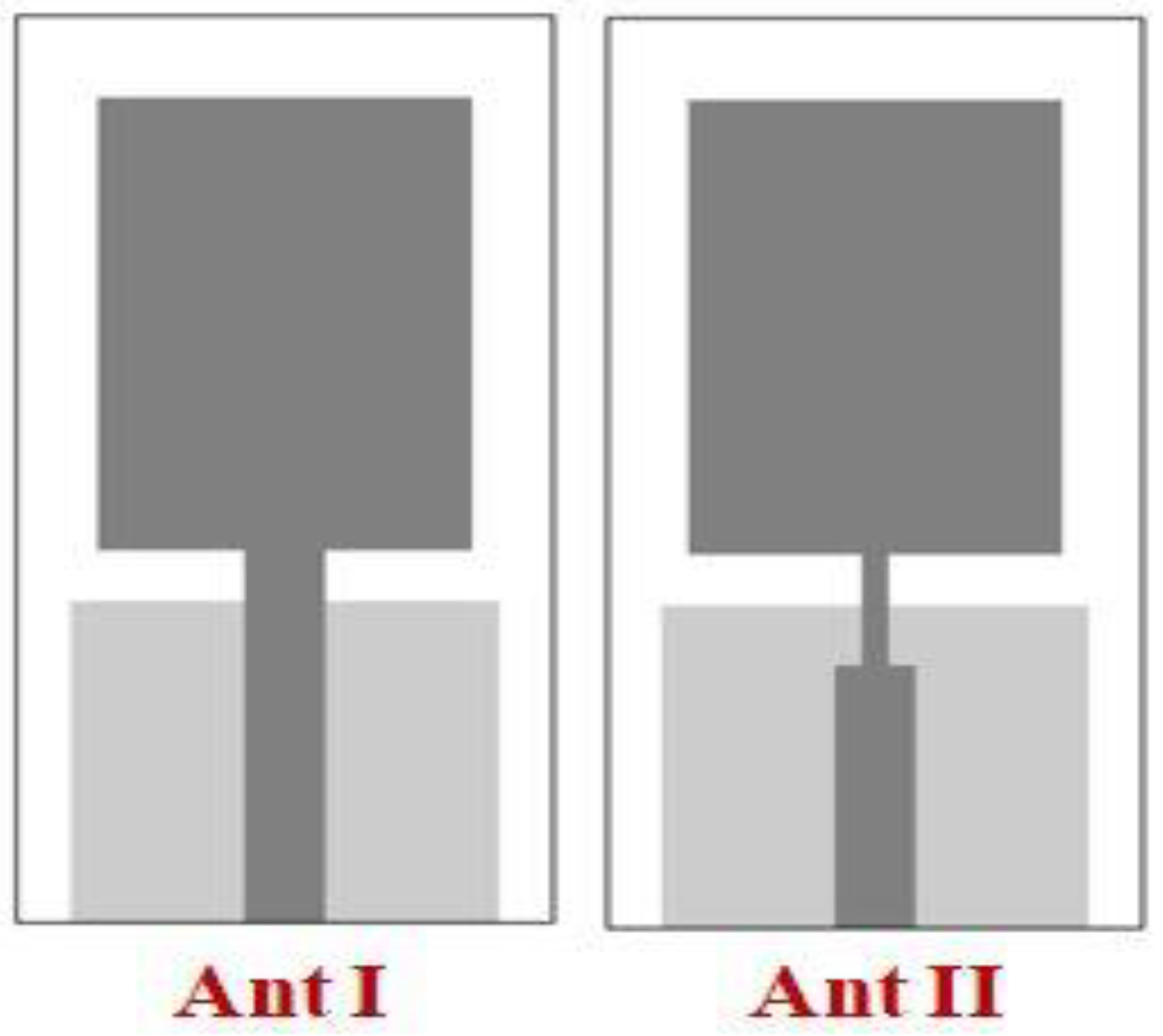
3. Design Process of the Sensing Antenna Linked with Port 1

The structure of the sensing antenna that operates at 2–12 GHz is shown in Figure 2. As depicted in Figure 3, the design process is finished in five steps. A traditional circular shaped monopole antenna (i.e., Ant I in Figure 3) is designed in the first step, and its impedance bandwidth ranges from 2.6 GHz to 10.6 GHz, as illustrated in Figure 4. The electrical lengthening is performed in the second step by combining a circular patch of radius R2 with the circular radiator of radius R1, as depicted in Ant II in Figure 3. As a result, the lower band edge (LBE) frequency of Ant II in Figure 1 is less than the LBE frequency of Ant I in Figure 4. However, the impedance matching of Ant II in Figure 4 at 3–5.75 GHz is poor. The electrical lengthening is further performed in the third step by combining a circular patch of radius R3 with the radiator of Ant II. Consequently, the LBE frequency of Ant III in Figure 4 becomes 2.07 GHz, which is less than the LBE frequency of Ant II in Figure 4, but the reflection coefficient curve of Ant III in Figure 4 is below −10 dB at 2.55–4.3 GHz and 8.1–8.8 GHz. So, to attain impedance matching throughout a wideband, i.e., 2–12 GHz, the ground plane of Ant IV in Figure 3 is made semi-elliptical shaped and some portion of the 50-ohm feed line is tapered towards the radiator. Thus, better impedance matching is achieved compared to Ant III in Figure 4, but the reflection coefficient of Ant IV is a bit better than −10 dB at 2.82–3.57 GHz and 5.56–6.34 GHz, as shown in Figure 4. In the last stage, good impedance matching is achieved over a wideband (i.e., 2–12 GHz) by etching a rectangle-shaped notch in the ground plane of Ant V.
As a result, the lower band edge (LBE) frequency of Ant II in Figure 1 is less than the LBE frequency of Ant I in Figure 4. However, the impedance matching of Ant II in Figure 4 at 3–5.75 GHz is poor. The electrical lengthening is further performed in the third step by combining a circular patch of radius R3 with the radiator of Ant II. Consequently, the LBE frequency of Ant III in Figure 4 becomes 2.07 GHz, which is less than the LBE frequency of Ant II in Figure 4, but the reflection coefficient curve of Ant III in Figure 4 is below −10 dB at 2.55–4.3 GHz and 8.1–8.8 GHz. So, to attain impedance matching throughout a wideband, i.e., 2–12 GHz, the ground plane of Ant IV in Figure 3 is made semi-elliptical shaped and some portion of the 50-ohm feed line is tapered towards the radiator. Thus, better impedance matching is achieved compared to Ant III in Figure 4, but the reflection coefficient of Ant IV is a bit better than −10 dB at 2.82–3.57 GHz and 5.56–6.34 GHz, as shown in Figure 4. In the last stage, good impedance matching is achieved over a wideband (i.e., 2–12 GHz) by etching a rectangle-shaped notch in the ground plane of Ant V.

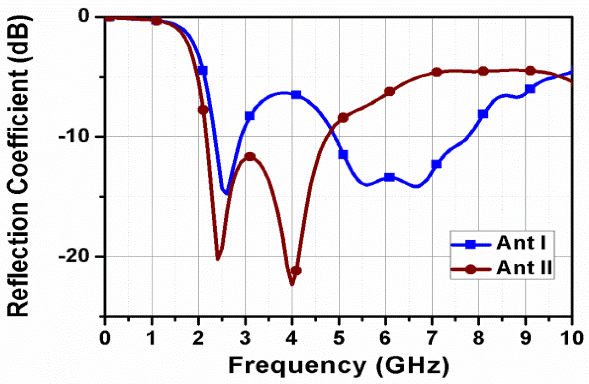
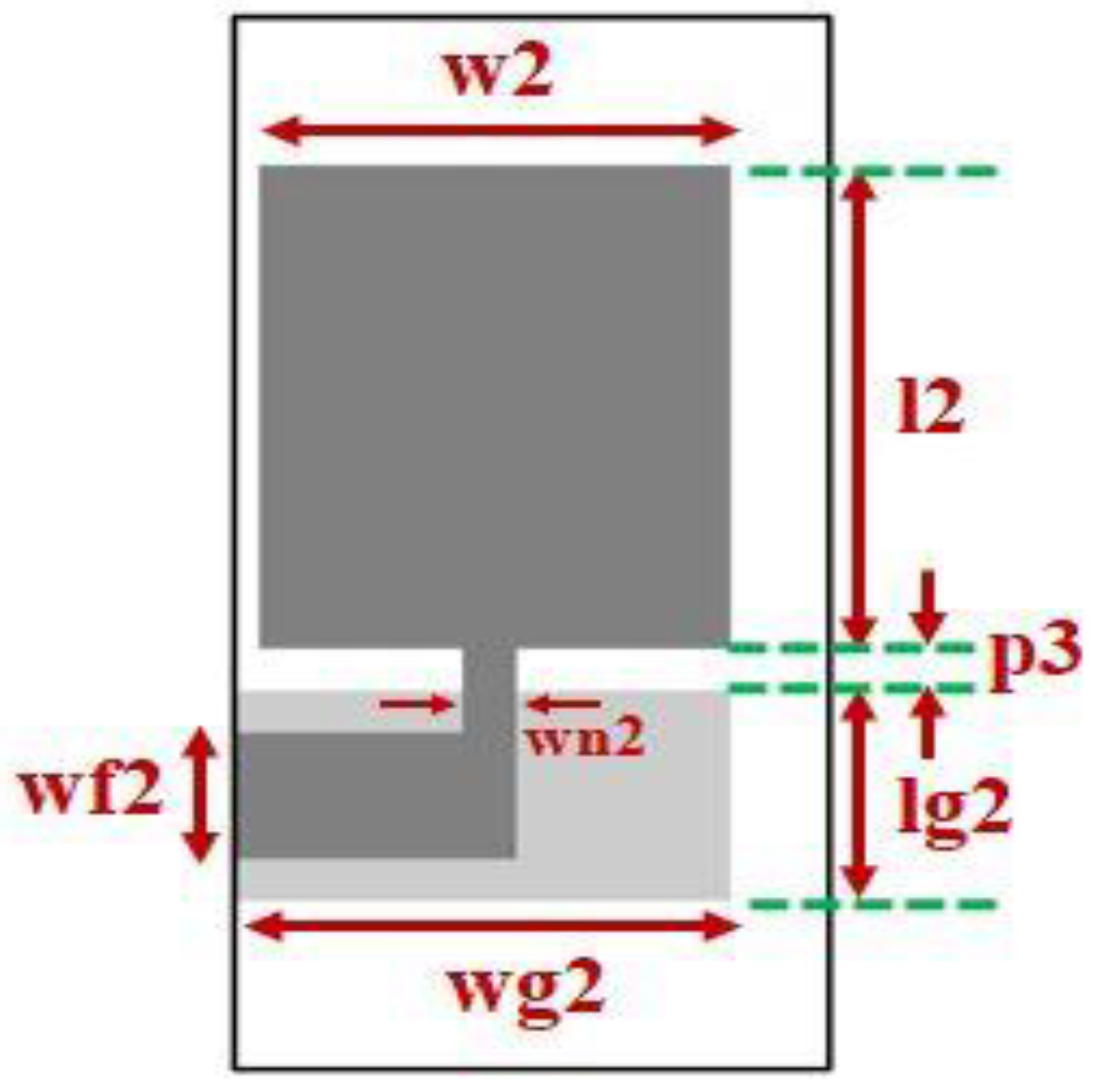
4. Design Process of the Communication Antennas Linked with P2 to P9

The structure of the antenna linked with port 2 is depicted in Figure 5. The antenna linked with port 2 is targeted to operate at low frequencies and its design process ends in two stages. In the first stage, a normal monopole antenna with rectangle-shaped patch is designed, as illustrated in Figure 6. Furthermore, this antenna is realized with an 8-element MIMO configuration at ports P2 to P9. Dimensions of the rectangular radiator are selected in such a way that the LBE frequency of the antenna linked with port 2 is about 2.3 GHz. The mathematical formula for calculating the LBE of Ant I in Figure 6 is given below.
f L A n t I ( P 2 ) = 7.2 l 1 + r 1 + p 2 × k   GHz
In Equation (1), l1 and p2 are the length of the rectangular patch and feed gap in centimeters, respectively. The term ‘r1′ in centimeters can be calculated from the width of rectangular patch since r1 =   w 1 2 π . The term ‘k’ is constant and is equal to 1.15.
After finding out the values of l1, r1, p2 and k, the LBE frequency of Ant I in Figure 1 is found as 2.3 GHz, whereas it is found as 2.34 GHz in simulation. It is evident from Figure 7 that Ant I operates at 2.34- 2.9 GHz and 4.9–7.75 GHz. As the antenna linked with port 2 is aimed to operate at low frequencies, a 1 mm width narrow strip line is placed between rectangular patch and the 50-ohm feed line of 3 mm width in the second stage, as depicted in Ant II in Figure 6. A parametric study is performed by altering the length of the 1 mm strip line, as depicted in Figure 8. It is obvious from Figure 8 that lower band edge frequency does not change much when the 1 mm strip line’s length changes. Additionally, bandwidth slightly decreases when the 1 mm strip line’s length increases. Finally, the 1 mm strip line’s length is selected as 5.5 mm as good impedance matching and large −10 dB reflection coefficient bandwidth (i.e., 2.17–4.75 GHz) are achieved.

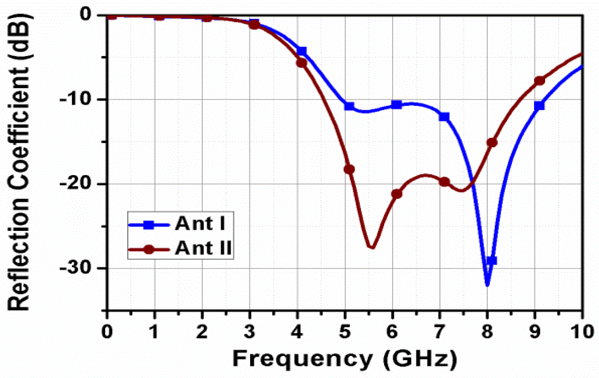
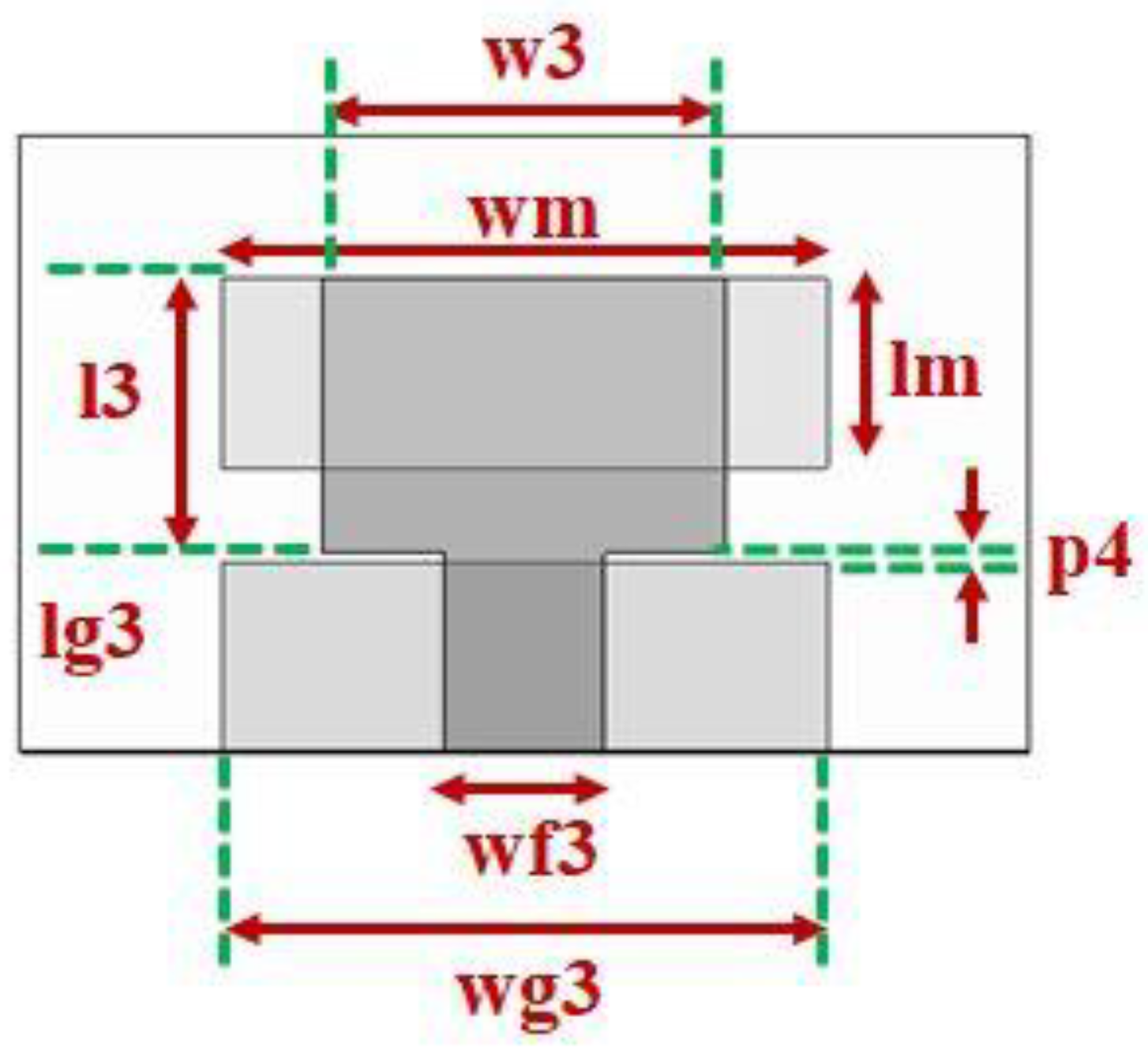
5. Design Process of the Communication Antennas Linked with P10 to P17

The structure of the communication antennas linked with port 10 is depicted in Figure 9. A bent microstrip line feed is used to achieve good impedance matching in the appropriate band.
The design process of the communication antenna linked with port 10 ends in two stages. In the first stage, a rectangular radiator of length 11.5 mm and width 9.5 mm is fed by a bent microstrip line feed, as depicted in Ant I in Figure 10. Furthermore, this antenna is realized with an 8-element MIMO configuration at ports P10 to P17. The mathematical formula for calculating the LBE of Ant I in Figure 10 is given below.
f L A n t I ( P 10 ) = 7.2 l 2 + r 2 + p 3 × k   G H z
In Equation (2), l2 and p3 are the length of the rectangular patch and feed gap in centimeters, respectively. The term ‘r2′ in centimeters can be calculated from the width of the rectangular patch since r2 =   w 2 2 π . The term ‘k’ is constant and is equal to 1.15. After finding out the values of l2, r2, p3 and k, the LBE frequency of Ant I in Figure 10 is found as 5.15 GHz, whereas it is found as 4.95 GHz in simulation, as shown in Ant I in Figure 11. In the next stage, the reflection coefficient performance is analyzed by altering the width of the strip line of length ln. As illustrated in Figure 12, the strip line of a width of 1.1 mm offers best impedance matching among different widths of strip line of length ln and the return loss is better than 10 dB in 4.6–8.7 GHz.

6. Design Process of the Communication Antennas Linked with P18 to P24

The structure of the communication antennas linked with P18 to P24 is depicted in Figure 13. Since the communication antennas linked with ports 2 and 10 are designed to operate at 2.17–4.74 GHz and 4.57–8.62 GHz, respectively, it is aimed to design a communication antenna that operates at frequencies which are greater than 8.62 GHz to cover the complete FCC UWB of 3.1–10.6 GHz. Furthermore, this antenna is realized with an 8-element MIMO configuration at ports P18 to P24. As depicted in Figure 14, the design process of the communication antenna linked with port 18 ends in two stages. In the first stage, a normal monopole antenna with a rectangle-shaped patch is designed, as illustrated in Figure 14. The length and width of the rectangular patch are selected in such a way that the LBE frequency is approximately 8.6 GHz.
The mathematical formula for calculating the LBE frequency of Ant I in Figure 14 is given as:
f L A n t I ( P 18 ) = 7.2 l 3 + r 3 + p 4 × k   G H z
where l3 and p4 are length of the rectangular patch and feed gap in centimeters, respectively. The term ‘r3′ in centimeters is expressed in terms of width of the rectangular patch (i.e., r3 =   w 3 2 π ). The term ‘k’ is constant and is equal to 1.15. After substituting the values of l3, r3, p4 and k in Equation (3), the LBE frequency of Ant I in Figure 14 is found as 8.6 GHz, whereas it is found as 8.5 GHz in simulation, as shown in Ant I in Figure 15.
It is seen from Figure 15 that the reflection coefficient curve of Ant I in Figure 1 is below −10 dB from 8.5 GHz and impedance matching is just decent. To make the lower band edge frequency 8.6 GHz and improve impedance matching, a rectangular-shaped patch is printed on the back portion of the substrate and the width of the 50-ohm feed line is chosen as 3.2 mm in the next stage. Figure 16 depicts a parametric study performed by altering the feed line’s width. It is concluded from Figure 16 that the desired performance is achieved with a feed line of a width of 3.2 mm.

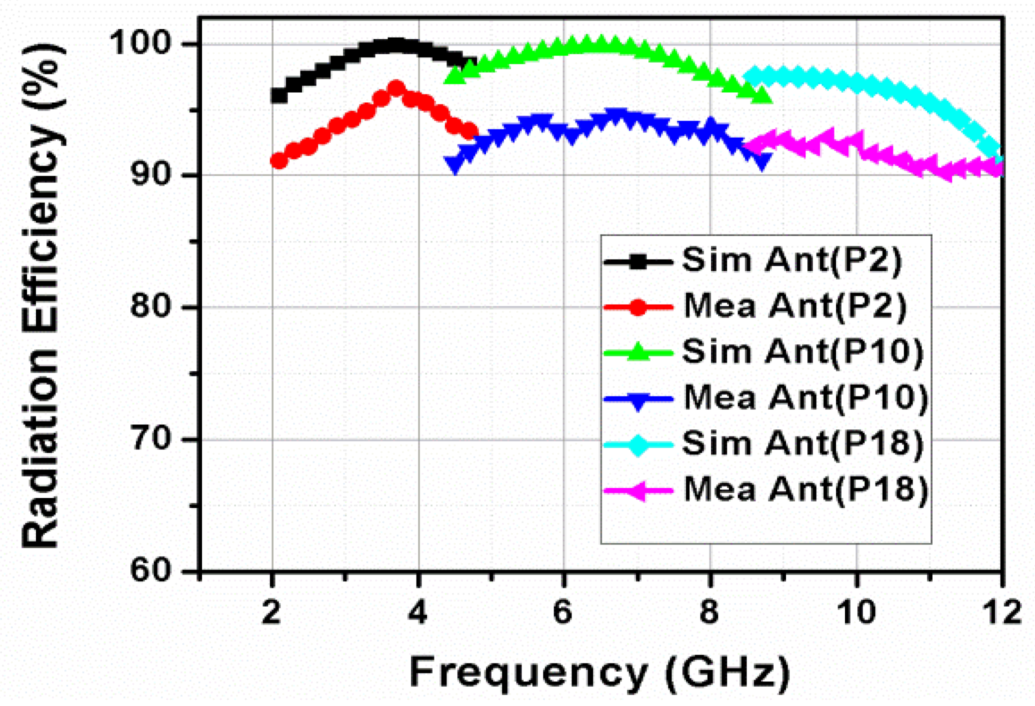
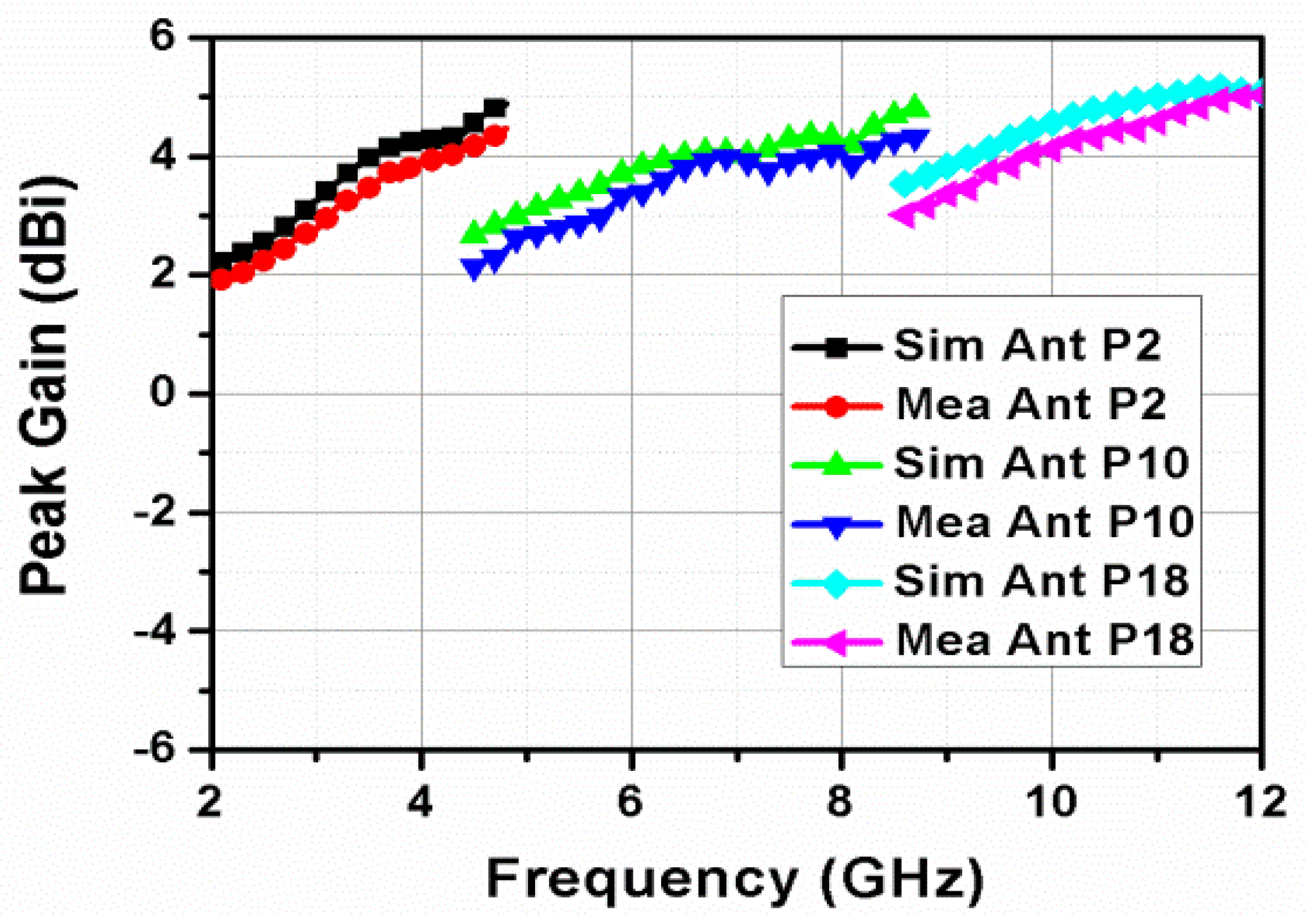
7. Results and Discussions

After designing a sensing antenna and three communication antennas, the sensing antenna and eight copies of each communication antenna are placed as depicted in Figure 17.
The reflection coefficients of all antennas in the proposed 25-port CR MIMO antenna are depicted in Figure 18, Figure 19 and Figure 20. An Agilent N5232A PNA-L network analyzer was used to check the correctness of the antenna. Good isolation between two antennas, without using any decoupling mechanism, can be attained in four possible cases. In the first case, low mutual coupling can be attained by placing two antennas in orthogonal fashion. In the second case, good isolation can be attained between two adjacent antennas that are similar to each other when the separation between those two antennas is greater than the one-fourth of the wavelength corresponding to their LBE frequency. In the third case, good isolation can be attained between two different antennas when the distance between them is greater than one-fourth of the wavelengths corresponding to their LBE frequencies. In the fourth case, if two similar antennas are even separated vertically at a distance that is slightly less than one-fourth of the wavelength corresponding to their LBE frequency, low mutual coupling can be attained between them. It can be seen from Figure 21, Figure 22 and Figure 23 that an isolation of better than 12 dB is attained without using any decoupling mechanisms.
In the proposed 25-port MIMO antenna system, if any two antennas are considered, they come under any one of the above four discussed cases. Hence, all the antennas in the proposed 25-port CR MIMO antenna system are well isolated. The mutual coupling of other possible combinations is not shown in Figure 21, Figure 22 and Figure 23 since two antennas in those combinations are separated by large distances. So, mutual coupling of better than −15 dB is guaranteed. Pyramidal horn antenna and the proposed CR MIMO antenna are used as transmitting and receiving antennas, respectively, in an anechoic chamber while measuring radiation patterns. A microwave analog signal generator is used to connect the transmitting antenna. In the far-field region, the designed antenna connected to a coaxial detector is kept in receiving mode and used as receiving antenna. The far-field patterns of the sensing antenna are depicted in Figure 24. The communication antennas linked with ports 2, 10 and 18 are illustrated in Figure 25, Figure 26 and Figure 27, respectively. Dipole-natured patterns and nearly omnidirectional patterns are attained at low (2.5 and 5 GHz) and high frequencies (7.5 and 10 GHz), respectively, whereas dipole-natured patterns are attained in both the planes in case of communication antennas. The far-field patterns of the communication antennas accessed at ports 2, 10 and 18 are similar to that of a dipole antenna at 3 GHz, 6 GHz and 9 GHz, respectively, as depicted in Figure 25, Figure 26 and Figure 27.
The slight shifts and little deviations in the resonances of the reflection coefficient curves may be because of the faults in fabrication of the prototype, material impurities, and imperfections in soldering and connector losses. However, the measured reflection coefficients of all the communication antennas in the 25-port MIMO antenna are below −10 dB in their impedance bandwidths, which indicates that the simulated reflection coefficient results of the 25-port CR MIMO antenna are in good agreement with the measured reflection coefficient results. The cross polarization levels of all the antennas in the proposed antenna are less than −20 dB, as shown in Figure 24, Figure 25, Figure 26 and Figure 27. It indicates that the vertically polarized surface currents are more dominant than the horizontally polarized surface currents in all the antennas in the proposed 25-port CR MIMO antenna. Moreover, the obtained omnidirectional radiation patterns of all the antennas are well suitable for CR MIMO applications.
The radiation efficiency and peak gain of the sensing antenna are illustrated in Figure 28 and Figure 29, respectively. It is seen that the simulated peak gain and radiation efficiency of the sensing antenna are better than 82% and 2.25 dBi, respectively. The radiation efficiencies and peak gains of the communication antennas are illustrated in Figure 30 and Figure 31, respectively. It is obvious from Figure 30 and Figure 31 that the simulated peak gains and radiation efficiencies of the sensing antenna are better than 90% and 2.5 dBi, respectively. The measured peak gains are slightly less than the simulated peak gains because of substrate losses, magnetic field of the earth and errors in measurement. The fabricated prototype of the proposed 25-port CR MIMO antenna is provided in Figure 32.
It can be observed from Table 3 that no CR 8-element MIMO antennas appear in the existing literature. Additionally, the proposed 8-element MIMO antenna achieves polarization diversity and covers all communication bands from 2.17 to 12 GHz. Moreover, it does not have any switching elements such as PIN diodes, MEMS, varactor diodes, or other factors.

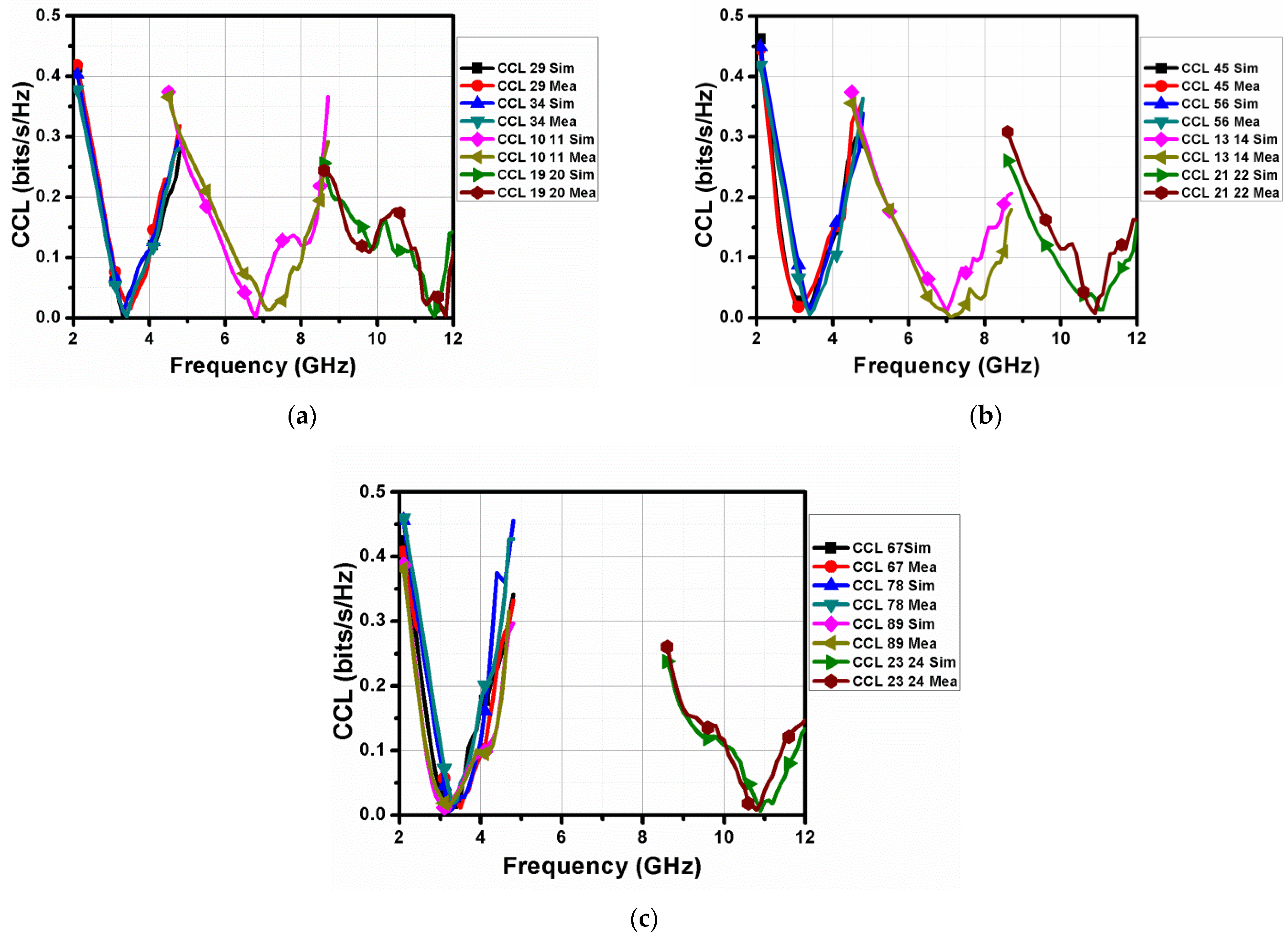
8. Performance Analysis of the 25-port CR MIMO Antenna

The diversity characteristics of the proposed MIMO antenna can be assessed by the two parameters diversity gain (DG) and the envelope correlation coefficient (ECC) [27,28,29,30]. ECC can be calculated mathematically by using the S-parameters, as shown in Equation (4). An ideal MIMO antenna system has an ECC of 0. ECC of the proposed 8-element MIMO antenna is illustrated in Figure 1. DG can be determined mathematically once ECC is known using the equation given in Equation (1), and its ideal value for a good MIMO antenna system is 10 dB.
ECC ( ρ ) = | S ii * S ii + S ji * S jj | 2 ( 1 - | S ii | 2 | S ij | 2 ) ( 1 - | S ji | 2 | S jj | 2 )
ECC ( ρ ) = | 4 π [ F i ( θ , f ) * F j ( θ , f ) ] d Ω | 2 4 π | F i ( θ , f ) | 2 d Ω 4 π | F j ( θ , f ) | 2 d Ω
where i, j N, i < j, j 4, F i θ , is nothing but the far-field pattern of the antenna when port i and port j are excited, and * denotes the Hermitian product. However, calculation of ECC using far-field patterns is very tedious. After ECC is calculated, DG in dB can be determined using Equation (6).
Diversity   Gain   ( dB ) = 10 × 1 - 0.99 ρ 2
The quality of the proposed 25-port CR MIMO antenna system can be assessed by another crucial parameter called channel capacity loss (CCL). When the number of antennas increases, channel capacity increases under certain conditions without increasing transmitted power or bandwidth. However, channel capacity decreases when a correlation between the links exists. Additionally, as the correlation increases, CCL increases. CCL can be calculated from the equation [27,28,29,30] given below.
C loss = log 2 det ( Ψ R )
where Ψ R represents correlation matrix of the receiving antenna. Its matrix representation is given below.
Ψ R = ( ρ 11 ρ 12 ρ 21 ρ 22 )
ρ ii = 1 | S ii | 2 | S ij | 2   and   ρ ij = ( | S ii * S ij + S ji * S jj | )
It is evident from Figure 33 that the ECC of the proposed 25-port CR MIMO antenna is less than 0.42 and DG of the proposed 25-port CR MIMO antenna is more than 9.1 dB. It can also be clearly seen that the CCL of the proposed 25-port CR MIMO antenna is less than 0.46 bits/s/Hz, as illustrated in Figure 34. Since the acceptable level of ECC and CCL of a good MIMO are 0.5 and 0.5 bits/s/Hz, the proposed 25-port CR MIMO antenna is well suitable for CR MIMO applications.
The total active reflection coefficient (TARC) is one of the crucial parameters to evaluate the diversity performance of the antenna. It is nothing but the ratio of total incident power to the total power that is outgoing when a multiport antenna system is present. It can be calculated using the Equation (10) given in [27].
TARC = k = 1 N b k 2 k = 1 N a k 2
where a is the excitation parameter and b is the scattering parameter in Equation (10). In order to check the effect of TARC on the 10 dB return loss bandwidth of the communication antennas, the proposed MIMO antenna is integrated with an ideal phase shifter in which scan angle is changed from 45° to 180°. It is obvious from Figure 35 that TARC for all 8-element communication antennas is less than −10 dB. So, it is confirmed that all the power that is delivered is accepted by the other antenna element without affecting the 10 dB return loss bandwidth of 8-element MIMO communication antennas.
Mean effective gain (MEG) is another important parameter to assess the diversity performance of the antenna in wireless channels. It ascertains the antenna element’s ability to accept electromagnetic signals in the presence of rich fading channels. Practically, it ranges from −3 dB to −12 dB for a MIMO antenna with good diversity performance. It is evident from Figure 36 that the MEG for all MIMO communication antennas is less than −3 dB. So, it can be concluded that the 8-element MIMO communication antennas is a promising candidate for CR MIMO applications.

9. Conclusions

In this article, a CR-integrated antenna system, which can perform maximum of three communication operations, has been presented to improve spectrum utilization efficiency. The sensing antenna linked to port 1 was able to sense the spectrum that ranges from 2 to 12 GHz, whereas the communication MIMO antennas linked with ports 2 to 9, ports 10 to 17 and ports 18 to 25 perform operations in the 2.17–4.74 GHz, 4.57–8.62 GHz and 8.62–12 GHz bands, respectively. Mutual coupling in the proposed CR MIMO antenna was less than −12 dB. Peak gain and radiation efficiency of the sensing antenna are found to be better than 2.25 dBi and 82%, respectively, whereas the peak gains and radiation efficiencies of all communication antennas were more than 2.5 dBi and 90%, respectively. It is inexpensive, easily implementable and has less complexity compared to the traditional reconfigurable CR MIMO antennas. Additionally, it can overcome all the drawbacks that are associated with reconfigurable CR MIMO antennas. Its performance has also been assessed by evaluating ECC, DG, CCL, TARC and MEG. The simulated and measured ECC, DG, CCL, TARC and MEG are within their acceptable limits. Hence, the proposed CR MIMO antenna is a promising candidate for CR MIMO applications.

Author Contributions

Conceptualization: D.S., A.N., R.M., A.B. and S.D.; methodology: D.S., A.N., S.D., S.L. and A.B.; software: D.S., A.B., A.D.A. and W.E.-S.; validation: A.D.A., W.E.-S. and S.L.; writing—original draft preparation: D.S., A.N. and S.D.; writing—review, and editing: S.L., W.E.-S. and R.M.; supervision: S.D., A.N., R.M. and A.B.; project administration: W.E.-S.; funding acquisition A.D.A. All authors have read and agreed to the published version of the manuscript.

Funding

This work is supported by Princess Nourah bint Abdulrahman University Researchers Supporting Project number (PNURSP2023R51), Princess Nourah bint Abdulrahman University, Riyadh, Saudi Arabia.

Institutional Review Board Statement

Not applicable.

Informed Consent Statement

Not applicable.

Data Availability Statement

The data presented in this research are available on request from the corresponding author.

Acknowledgments

The authors would like to acknowledge the Princess Nourah bint Abdulrahman University Researchers Supporting Project number (PNURSP2023R51), Princess Nourah bint Abdulrahman University, Riyadh, Saudi Arabia.

Conflicts of Interest

The authors declare no conflict of interest.

References

  1. Riaz, S.; Zhao, X.; Geng, S. A Frequency Reconfigurable MIMO Antenna with Agile Feedline for Cognitive Radio Applications. Int. J. RF Microw. Comput. Aided Eng. 2019, 30, e22100. [Google Scholar]
  2. Hussain, R.; Raza, A.; Khan, M.U.; Shammim, A.; Sharawi, M.S. Miniaturized Frequency Reconfigurable Pentagonal MIMO Slot Antenna for Interweave CR Applications. Int. J. RF Microw. Comput. Aided Eng. 2019, 29, e21811. [Google Scholar] [CrossRef]
  3. Alam, T.; Thummaluru, S.R.; Chaudhary, R.K. Integration of MIMO and Cognitive Radio for Sub-6 GHz 5G Applications. IEEE Antennas Wirel. Propag. Lett. 2019, 18, 2021–2025. [Google Scholar] [CrossRef]
  4. Cheng, S.; Lin, K. A Reconfigurable Monopole MIMO Antenna with Wideband Sensing Capability for Cognitive Radio using Varactor Diodes. In Proceedings of the IEEE International Symposium on Antennas and Propagation & USNC/URSI National Radio Science Meeting, Vancouver, BC, Canada, 19–24 July 2015; pp. 2233–2234. [Google Scholar]
  5. Thummaluru, S.R.; Ameen, M.; Chaudhary, R.K. Four-Port MIMO Cognitive Radio System for Midband 5G Applications. IEEE Trans. Antennas Propag. 2019, 67, 5634–5645. [Google Scholar] [CrossRef]
  6. Zhao, X.; Riaz, S.; Geng, S. A Reconfigurable MIMO/UWB MIMO Antenna for Cognitive Radio Applications. IEEE Access 2019, 7, 46739–46747. [Google Scholar] [CrossRef]
  7. Hussain, R.; Sharawi, M.S. A Cognitive Radio Reconfigurable MIMO and Sensing Antenna System. IEEE Antennas Wirel. Propag. Lett. 2015, 14, 257–260. [Google Scholar] [CrossRef]
  8. Pahadsingh, S.; Sahu, S. Four Port MIMO Integrated Antenna System with DRA for Cognitive Radio Platforms. AEU-Int. J. Electron. Commun. 2018, 92, 98–110. [Google Scholar] [CrossRef]
  9. Hussain, R.; Khan, M.U.; Sharawi, M.S. An Integrated Dual MIMO Antenna System with Dual-Function GND-Plane Frequency Agile Antenna. IEEE Antennas Wirel. Propag. Lett. 2018, 17, 142–145. [Google Scholar] [CrossRef]
  10. Alam, T.; Thummaluru, S.R.; Chaudhary, R.K. Improved Multifunctional MIMO Cognitive Radio System for Integrated Interweave-Underlay Operations. IEEE Trans. Microw. Theory Tech. 2022, 70, 631–640. [Google Scholar] [CrossRef]
  11. Jain, P.; Saptarshi, G. A Reconfigurable Four-Port MIMO Antenna for Sub-6 GHz Applications. In Proceedings of the IEEE Wireless Antenna and Microwave Symposium (WAMS), Rourkela, India, 5–8 June 2022; pp. 1–5. [Google Scholar]
  12. Mansoul, A.; Mourad, N. Compact and Reconfigurable Multiband 2-Element MIMO Slot Antenna for Advanced Communication Systems. In Proceedings of the IEEE International Symposium on Antennas and Propagation and North American Radio Science Meeting, Montreal, QC, Canada, 5–10 July 2020; pp. 575–576. [Google Scholar]
  13. Hussain, R.; Sharawi, M.S. 4-Element Planar MIMO Reconfigurable Antenna System for Cognitive Radio Applications. In Proceedings of the IEEE International Symposium on Antennas and Propagation & USNC/URSI National Radio Science Meeting, Vancouver, BC, Canada, 19–24 July 2015; pp. 717–718. [Google Scholar]
  14. Hussain, R.; Sharawi, M.S.; Shamim, A. 4-Element Concentric Pentagonal Slot-Line-Based Ultra-Wide Tuning Frequency Reconfigurable MIMO Antenna System. IEEE Trans. Antennas Propag. 2018, 66, 4282–4287. [Google Scholar] [CrossRef]
  15. Chacko, B.P.; Augustin, G.; Denidni, A. Electronically Reconfigurable Uniplanar Antenna with Polarization Diversity for Cognitive Radio Applications. IEEE Antennas Wirel. Propag. Lett. 2015, 14, 213–216. [Google Scholar] [CrossRef]
  16. Hussain, R.; Sharawi, M.S.; Shamim, A. An Integrated Four-Element Slot-Based MIMO and a UWB Sensing Antenna System for CR Platforms. IEEE Trans. Antennas Propag. 2018, 66, 978–983. [Google Scholar] [CrossRef] [Green Version]
  17. Tawk, Y.; Constantine, J.; Christodoulou, C.G. Reconfigurable Filtennas and MIMO in Cognitive Radio Applications. IEEE Trans. Antennas Propag. 2014, 62, 1074–1083. [Google Scholar] [CrossRef]
  18. Islam, H.; Das, S.; Ali, T.; Bose, T.; Prakash, O.; Kumar, P. A Frequency Reconfigurable MIMO Antenna with Bandstop Filter Decoupling Network for Cognitive Communication. Sensors 2022, 22, 6937. [Google Scholar] [CrossRef]
  19. Hussain, R.; Sharawi, M.S. An Integrated Slot-Based Frequency-Agile and UWB Multifunction MIMO Antenna System. IEEE Antennas Wirel. Propag. Lett. 2019, 18, 2150–2154. [Google Scholar] [CrossRef]
  20. Nella, A.; Abhay, S.G. A survey on planar antenna designs for cognitive radio applications. Wirel. Pers. Commun. 2018, 98, 541–569. [Google Scholar] [CrossRef]
  21. Nella, A.; Abhay, S.G.; Vigneswaran, D. Cognitive radio paradigm and recent trends of antenna systems in the UWB 3.1–10.6 GHz. Wirel. Netw. 2020, 26, 3257–3274. [Google Scholar]
  22. Srikar, D.; Anuradha, S. Twelve Port MIMO Antenna with Polarisation Diversity for Cognitive Radio Applications. Electron. Lett. 2019, 55, 1165–1168. [Google Scholar] [CrossRef]
  23. Srikar, D.; Anuradha, S. A Compact Six Port Antenna for Better Spectrum Utilization Efficiency in Cognitive Radio Applications. Int. J. RF Microw. Comput. Aided Eng. 2020, 30, e22383. [Google Scholar] [CrossRef]
  24. Srikar, D.; Anuradha, S. A New Two-Element MIMO Antenna System for Cognitive Radio Applications. Circuit World 2022, 48, 111–125. [Google Scholar] [CrossRef]
  25. Nella, A.; Gandhi, A.S. A Five-Port Integrated UWB and Narrowband Antennas System Design for CR Applications. IEEE Trans. Antennas Propag. 2018, 66, 1669–1676. [Google Scholar] [CrossRef]
  26. Anvesh Kumar, N.; Gandhi, A.S. A Compact Novel Three-Port Integrated Wide and Narrow Band Antennas System for Cognitive Radio Applications. Int. J. Antennas Propag. 2016, 2016, 2829357. [Google Scholar]
  27. Nandi, S.; Mohan, A. CRLH Unit Cell Loaded Triband Compact MIMO Antenna for WLAN/WiMAX Applications. IEEE Antennas Wirel. Propag. Lett. 2017, 16, 1816–1819. [Google Scholar]
  28. Balaji, V.R.; Tathababu, A.; Arpan, D.; Anveshkumar, N.; Truong, K.N. An Inverted L-Strip Loaded Ground with Hollow Semi-Hexagonal Four-Element Polarization Diversity UWB-MIMO Antenna. Trans. Emerg. Telecommun. Technol. 2022, 33, e4381. [Google Scholar] [CrossRef]
  29. Sharma, P.; Tiwari, R.N.; Singh, P.; Kumar, P.; Kanaujia, B.K. MIMO Antennas: Design Approaches, Techniques and Applications. Sensors 2022, 22, 7813. [Google Scholar] [CrossRef]
  30. Addepalli, T.; Desai, A.; Elfergani, I.; Anveshkumar, N.; Kulkarni, J.; Zebiri, C.; Rodriguez, J.; Abd-Alhameed, R. 8-Port Semi-Circular Arc MIMO Antenna with an Inverted L-Strip Loaded Connected Ground for UWB Applications. Electronics 2021, 10, 1476. [Google Scholar] [CrossRef]
Figure 1. Geometry of the 25-port CR MIMO antenna. (a) Structure of the antenna. (b) Top view. (c) Back view.
Electronics 12 00330 g001
Figure 2. Schematic of the antenna linked with port 1.
Electronics 12 00330 g002
Figure 3. Evolution of antenna linked with port 1.
Electronics 12 00330 g003
Figure 4. Evolution of the antenna linked with port 1.
Electronics 12 00330 g004
Figure 5. Schematic of the antennas linked with P2 to P9.
Electronics 12 00330 g005
Figure 6. Evolution of the antennas linked with P2 to P9.
Electronics 12 00330 g006
Figure 7. Reflection coefficients of the antennas in intermediate steps of the antenna linked with port 2.
Electronics 12 00330 g007
Figure 8. Reflection coefficients of the antenna linked with port 2 for different values of ln1.
Electronics 12 00330 g008
Figure 9. Schematic of the antennas linked with P10 to P17.
Electronics 12 00330 g009
Figure 10. Evolution of the antennas linked with P10 to P17.
Electronics 12 00330 g010
Figure 11. Reflection coefficients of the antennas in intermediate steps of the antenna linked with port 10.
Electronics 12 00330 g011
Figure 12. Reflection coefficients of the antenna linked with port 10 for different values of wn2.
Electronics 12 00330 g012
Figure 13. Schematic of the antennas linked with P18 to P24.
Electronics 12 00330 g013
Figure 14. Evolution of the antennas linked with P18 to P24.
Electronics 12 00330 g014
Figure 15. Reflection coefficients of the antennas in intermediate steps of the antenna linked with port 18.
Electronics 12 00330 g015
Figure 16. Reflection coefficient of the antenna linked with port 10 for different values of wf3.
Electronics 12 00330 g016
Figure 17. Inter-elemental spacing of the 25-port CR MIMO antenna.
Electronics 12 00330 g017
Figure 18. Plot of (a) S11, (b) S22, (c) S33, (d) S44, (e) S55, (f) S66, (g) S77, (h) S88, (i) S99.
Electronics 12 00330 g018aElectronics 12 00330 g018b
Figure 19. Plot of (a) S10 10, (b) S11 11, (c) S12 12, (d) S13 13, (e) S14 14, (f) S15 15, (g) S16 16, (h) S17 17.
Electronics 12 00330 g019
Figure 20. Plot of (a) S18 18, (b) S19 19, (c) S20 20, (d) S21 21, (e) S22 22, (f) S23 23, (g) S24 24, (h) S25 25.
Electronics 12 00330 g020aElectronics 12 00330 g020b
Figure 21. Mutual coupling between sensing and communication antennas (a) S21, S31, and S41 (b) S10 1, S11 1, S12 1, and S18 1.
Electronics 12 00330 g021
Figure 22. Mutual coupling between identical communication antennas (a) S29, S34, S45, and S56 (b) S67, S78, S89, and S10 11 (c) S13 14, S19 20, S21 22, and S23 24.
Electronics 12 00330 g022aElectronics 12 00330 g022b
Figure 23. Mutual coupling between non-identical communication antennas. (a) S2 10, S12 18, S3 12, and S4 13 (b) S5 14, S5 19, S15 20, and S6 15 (c) S21 6, S7 22, S7 16, and S16 23 (d) S24 8, S8 25, S17 25, and S9 17.
Electronics 12 00330 g023
Figure 24. Far-field patterns of the sensing antenna in orthogonal planes at (a) 2.5 GHz (XZ), (b) 2.5 GHz (YZ), (c) 5 GHz (XZ), (d) 5 GHz (YZ), (e) 7.5 GHz (XZ), (f) 7.5 GHz (YZ), (g) 10 GHz (XZ), (h) 10 GHz (YZ).
Electronics 12 00330 g024
Figure 25. Far-field patterns of the communication antenna linked with port 2 at (a) 3 GHz (XZ) and (b) 3 GHz (YZ).
Electronics 12 00330 g025
Figure 26. Patterns of the communication antenna linked with port 10 at 6 GHz in (a) XZ and (b) YZ.
Electronics 12 00330 g026
Figure 27. Far-field patterns of the communication antenna linked with port 18 at (a) 9 GHz (XZ) and (b) 9 GHz (YZ).
Electronics 12 00330 g027
Figure 28. Radiation efficiency of the sensing antenna.
Electronics 12 00330 g028
Figure 29. Peak gain of the sensing antenna.
Electronics 12 00330 g029
Figure 30. Radiation efficiencies of the communication antennas.
Electronics 12 00330 g030
Figure 31. Peak gains of the communication antennas.
Electronics 12 00330 g031
Figure 32. Fabricated prototype of the 25-port CR MIMO antenna. (a) Top view. (b) Bottom view.
Electronics 12 00330 g032
Figure 33. ECC and DG of the 25-port CR MIMO antenna. (a) ECC 29, ECC 34, ECC 10 11 and ECC 19 20(b) ECC 45, ECC 56, ECC 13 14 and ECC 21 22 (c) ECC 67, ECC 78, ECC 89 and ECC 23 24 (d) DG 29, DG 34, DG 10 11 and DG 19 20 (e) DG 45, DG 56, DG 13 14 and DG 21 22 (f) DG 67, DG 78, DG 89 and DG 23 24.
Electronics 12 00330 g033
Figure 34. CCL of the 25-port CR MIMO antenna. (a) CCL 29, CCL 34, CCL 10 11 and CCL 19 20 (b) CCL 45, CC 56, CCL 13 14 and CCL 21 22 (c) CCL 67, CCL 78, CCL 89 and CCL 23 24.
Electronics 12 00330 g034
Figure 35. TARC of the 8-element communication antennas associated with (a) ports 2 to 9, (b) ports 10 to 17, and (c) ports 18 to 25.
Electronics 12 00330 g035
Figure 36. MEG of the 8-element communication antennas associated with (a) ports 2 to 9, (b) ports 10 to 17, and (c) ports 18 to 25.
Electronics 12 00330 g036aElectronics 12 00330 g036b
Table 1. Specifications of the 25-port CR MIMO antenna.
AntennaUsage10 dB Return Loss Bandwidth
Ant (P1)Sensing2–12 GHz
Ant (P2) to Ant (P9)Communication2.17–4.74 GHz
Ant (P10) to Ant (P17)Communication4.57–8.62 GHz
Ant (P18) to Ant (P25)Communication8.62–12 GHz
Table 2. Dimensions of the 25-port CR MIMO antenna.
ParameterDimension (mm)ParameterDimension (mm)
R18.78l122.5
R25.28w114
R34lg116
p11.16wg116
lg5ln15.5
wg18.98wn11
wf3p22.5
ln1.57lw113
wn4.5wf13
p40.2l211.5
wf33.2w29.5
W160L160
lg25w38
wg210 lm4
wf23wm12
wn21.1lg34
p30.95wg312
l35.8g11.16
Table 3. Comparison of the 25-port CR MIMO antenna with other antennas in the literature.
Ref.Size (mm2)Range of the Sensing Antenna (GHz)Range Covered by Communication Antennas (GHz)Min. Isolation (dB)n-Element MIMO AntennaReconfiguration Mechanism
[1]50 × 100-1.42–2.27122Varactor diodes
[2]60 × 120-3.2–3.9 104Varactor diodes
[3]109 × 1092–5.72.5–4.2154PIN and Varactor diodes
[4]60 × 402.2–72.3–6.3182Varactor diodes
[5]100 × 1202.3–5.52.5–4.2154PIN and Varactor diodes
[6]60 × 1201–4.50.9–2.612.52PIN and Varactor diodes
[7]65 × 1200.72–3.44A few frequencies in 0.72–3.4415.52PIN and Varactor diodes
[8]52.2 × 351.7–10.65.1–5.5, 6.6–7.2 and 9.7–10.2152-
[9]50 × 110-1.73–2.28 and 2.45102Varactor diodes
[10]110 × 702.45–5.32.5–3.6124Varactor diodes
[11]152 × 1262.4–65.8–6.3204PIN diodes
[12]24 × 25-2.4, 3.5, 5.25 252PIN diodes
This work160 × 1602–12All frequencies in 2.17–12128-
Disclaimer/Publisher’s Note: The statements, opinions and data contained in all publications are solely those of the individual author(s) and contributor(s) and not of MDPI and/or the editor(s). MDPI and/or the editor(s) disclaim responsibility for any injury to people or property resulting from any ideas, methods, instructions or products referred to in the content.

