Abstract
The source of energy extracted in renewable form has turned out to be a primary mainstream energy source, especially in the telecom sectors. Rapid growth of renewable sources has led to telecom operators concentrating more on designing the system with appropriate energy storage elements, providing control facilities, improving system efficiency and verifying uninterrupted power supplies. Therefore, this paper gives a novel approach of utilizing embedded control in energy generation consisting of a solar-wind hybrid energy system placed in isolated areas. For the purpose of integration of wind, together with the solar energy sources, into an increasingly efficient system, a single Cuk-Luo integrated DC-DC converter has been put forward. The proposed system has been modeled using MATLAB/Simulink and verified under various combinations of solar-wind energy sources without compromising the required power. In order to verify the proposed Cuk-Luo integrated converter with the energy management controller system, a prototype hardware is implemented and tested.
1. Introduction
Mobile networks have gained more interest in modern communications [,]. According to Bhattacharya et al. [] and Kumar et al., [], the use of mobile networks raises a crucial concern regarding their energy consumption, environmental protection and carbon footprint. The nature-friendly energy sources, coupled with suitable energy storage elements, could turn out to be the major source in the reduction of discharge through greenhouse gases. However, renewable energy relies on wind speed or solar radiation to a large extent. In order to offer a continuous supply by taking the advantages of the complementary nature of both of the energy sources, the solution is to hybridize the two types of sources in the form of the microgrid. A study performed by Bhattacharya et al. [], Joga Rao et al. [] and Pandiyan et al. [] demonstrated that a hybrid solar-wind power system can offer a cost effective and environmentally protected solution. On the other hand, the intermittent nature of Renewable Energy Sources (RES) means proper energy management is required in order to improve the performance and increase the lifespan of the microgrid components to a large extent []. Therefore, sufficient management of the energy flow through the hybrid RES and the establishment of a supervisory system are highly in demand. Energy storage systems are required to balance transient stability during the rapid change of solar and wind systems and load variations.
The literature reveals that new energy management techniques for PV/wind/grid RES have been carried out and several energy management systems have been evaluated to find the most effective one. In addition, there are works showing a dynamic energy management model and the development of a coordinated control strategy for a hybrid system maintaining around 75% battery state and DG power above 40% of its nominal value [].
From their analysis, it has been proved that a continuous and constant power is provided at two points, namely the load, together with the Point of Intersection with Common Coupling (PCC) []. Numerous variations of DC-DC-based converter topologies have been explored and compared in this paper. Initially, the authors Rashid [] and Mengi et al. [] discussed different DC-DC converters which are placed across each source of energy in parallel. Various independent converters are attached at an intersection point with common coupling, which ultimately is joined with a controller, purely independently. Major drawbacks of having such a type of system may arise due to problems such as being bulky, less efficient, having a large cumulative count of components, higher fare and complexity because of several stages involved in the converter [,]. Additionally, a requirement for individual controllers with a DC bus, common to all the controllers in every stage of conversion, leads to a system being disordered and having an increased cumulative weight. Shrivastava et al. [] and Ayang et al. [] have preferred mainly multi-input DC-DC converters to interface the number of storage devices and additional input sources of energy with the use of a primary power conversion arena with minimal part count and easier control.
A Non-isolated Three-Port DC–DC Converter with continuous input and output currents is based on Cuk topology, accommodating a PV cell and Fuel Cell []. A wind-electric system with a permanent magnet alternator, DC-DC buck-Boost or Cuk converter, diode rectifier, and a three-phase five-level inverter has appeared for a combined harmonic reduction and DC voltage regulation []. A substitute for the energy source that has made a lot of progress is the fuel cell. A proton exchange membrane fuel cell needs a DC-DC boost converter as an interface between the fuel cell and the load to give large-gain regulated voltage []. A new hybrid flyback-Cuk converter with a single switch, a single isolated input and dual output based on flyback and Cuk topologies has been discussed in [] for reduced switching losses. An isolated power-factor-corrected Cuk converter for brushless DC ceiling fan applications is proposed in []. The Cuk converter operates in continuous conduction mode, wherein the current multiplier control loop ensures a near-unity power factor and a low total harmonic distortion in the current. The current loop also provides over-current protection, enhancing the reliability of the system []. Neeraj et al. have evaluated the performance of solar-PV-based switched-capacitor high-step-up and non-isolated switched-inductor Cuk converters. []. The topologies implemented in this work have improved boosting ability compared to conventional Cuk and boost converters with lower voltage stress of the main switch. High conversion gain is needed for the grid integration of RES, like PV, fuel cells and wind. The combination of Cuk converters and voltage-multiplier units is provided and the converter utilizes a boost converter to give input to the Cuk converter, resulting in a rise in the gain value [].
The whale optimization algorithm is applied for the tuned Interleaved Luo Converter for the PV-array-fed BLDC motor driving centrifugal pumps. This is carried out when retrieving the generated power from the PV array using a positive interleaved Luo converter that boosts the output with low switching losses. []. The algorithm tunes the parameters of the PI controller to maintain the steady-state voltage at the output of the Luo converter. Chincholkar et al. have designed and analyzed a voltage mode non-linear control of a non-minimum-phase positive output elementary Luo converter. []. Gholizadeh et al. implemented single-switch step-up DC-DC converters based on cascaded boost and Luo converters [].
As per the report of the author [], a brief estimation of different components involved between conventional separate SEPIC, Cuk and Cuk-SEPIC fused converter has been presented. The efficiency obtained of conventional and proposed converters were 80% and 96%, respectively. The efficiency obtained of improved Cuk-buck and Cuk-buck converters [] were 92.69% and 83.38%, respectively. However, buck and SEPIC converters have a pulsating output current which needs a current handling capability. To reduce ripple voltage and current, Luo-type converters are usually employed [,].
In this paper, a primary dual input Cuk-Luo integrated-type converter employing an efficient solar-wind-battery system has been proposed, with the aim of addressing the performance gap faced in the Cuk converter and Luo converter individually. The converter presented here makes it feasible to employ dual-input solar-wind sources for sending power towards the load simultaneously or individually for making the conversion of energy with an increased performance.
For any renewable type of energy system with a hybrid mode, it is recommended to employ a sharp power management controller for the integration of cumulative elements of storage and sources of energy []. This literature focuses on a dedicated controller in order to manage the various inputs for consumption and investigate the power flow in the direction towards the load from the source [,].
The remaining portions of the paper are culminated as follows. Firstly, the primary structure of the converter system is presented, followed by descriptions of each block, namely, the various sources, operating modes and the controller in itself for energy management in the proposed system. These details are put forward in the second and third parts. The next section discusses the various results obtained from the simulation of the designed topology. The brief descriptions of the hardware are presented in fifth section, following which, the observations and findings of the investigations will be highlighted in the conclusion section.
2. Block Diagram
As described in the previous section, we begin with the proposition of a block diagram for the proposed solar-wind energy sources powered primarily by a Cuk-Luo integrated DC-DC converter having an inbuilt embedded controller used for applications such as powering telecom load, as presented in Figure 1.
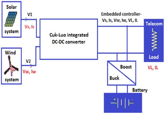
Figure 1.
Overview and Block diagram of the proposed system.
The above-stated system is physically composed with solar-wind hybrid energy sources [], Cuk-Luo integrated type converters and energy management and storage systems for controlling the duty cycle, as seen from the various input sources. These solar-wind-type energy sources are attached together in a parallel configuration by means of Cuk-Luo integrated into a converter for multiple purposes, namely, to power the battery in case of excess energy being generated and to power the load. Luo and Cuk converters are joined together in order to produce an efficient integrated converter.
The common components of Luo- and Cuk-based converters are joined among them. In case of any viability of wind and solar energy sources being available, energy is given to the load individually or altogether. Once the inability to meet the power expectation is found on the sources, the battery makes up for it as a compensation. Moreover, the selection of the battery is involved if it is able power the load by itself, lasting at least a day. Energy management using an embedded-based controller is achieved through regulating current together with the voltage, with the help of sources back to the load [,].
3. System Blueprint
3.1. Wind and Solar System
The sizes of Cuk-Luo segregated converters together with the solar-wind energy system have to determined based on mean day-to-day energy utilization by the BTS load. For the present situation, a solar panel comprising of a 53 V /22 A /1125 W rating is used.
Table 1 comprises various electrical parameters whose considerations are necessary for developing the solar storage source having an insolation of 1000 W/m2 and a temperature around 29 °C. The cumulative equation describing the I-V characteristics comprising of a single solar cell is shown below:
where
q—Charge of the electron (1.602 × 10⁻¹⁹ C)
k—Boltzman constant (1.3806 × 10⁻²³ J/K)
T—Temperature present in p-n junction
n—Constant for Diode ideality
IPV—Incident sunlight current
Io—Shockley diode equation.

Table 1.
Major electrical constraints of the solar system.
Table 1.
Major electrical constraints of the solar system.
| S.No | Solar Constraints | Gain |
|---|---|---|
| 1 | Voltage present at highest power | 53 V |
| 2 | Current present at highest power | 22 A |
| 3 | Reference temperature | 60 °C |
| 4 | Voc, open circuit voltage | 52.8 V |
| 5 | Isc, short circuit current | 21 A |
Among the different systems, wind-type storage has values of 323 V /3 A /1260 W. Table 2 corresponds to the electrical constraints that make up a wind system with the speed of 12 m/s. A primitive system comprises of a permanent magnet synchronous generator (PMSG), which is coupled to a wind turbine of a suitable head, together with a rectification staged circuit. Cumulative wind power (Pm), which is derived from the head of the turbine, can be obtained from the formula [],
where
Cp—Turbine’s coefficient of performance
Ρ—Density of air(kg/m3)
A—Coverage of turbine blades (m3)
w—Velocity of the wind (m/s)
λ—Ratio of tip speed on the rotor blade tip
β—Blade pitch angle (deg).
Table 2.
Electrical parameters of the wind system.
Table 2.
Electrical parameters of the wind system.
| S.No | Solar Parameters | Values |
|---|---|---|
| 1 | Wind speed | 12 m/s |
| 2 | Voltage present at highest power | 323 V |
| 3 | Current present at highest power | 3 A |
| 4 | Type of DC Machine | PMSM |
| 5 | Maximum power | 1260 W |
Based on Equations (1) and (2), Simulink modelling of solar cell and wind system was carried out and Figure 2a,b show the solar power, voltage and current, and the wind power, voltage, and current, respectively [,].
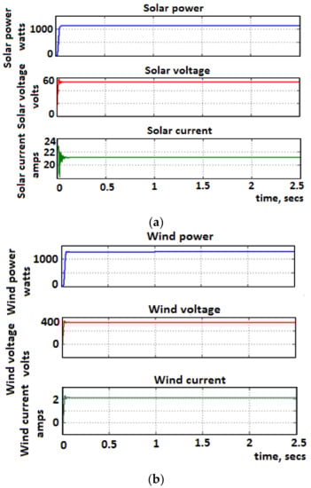
Figure 2.
(a) Solar power, voltage and current. (b) Wind power, voltage and current.
3.2. Cuk-Luo Integrated Converter
The Cuk-Luo integrated converter circuit used in the application of telecom-load powering with the help of the solar-wind system is presented in Figure 3. As shown, it utilizes both Luo and Cuk converters. The Cuk converter has a regulation method for stepping down, making it feasible in minimal-voltage-rating systems such as BTS.
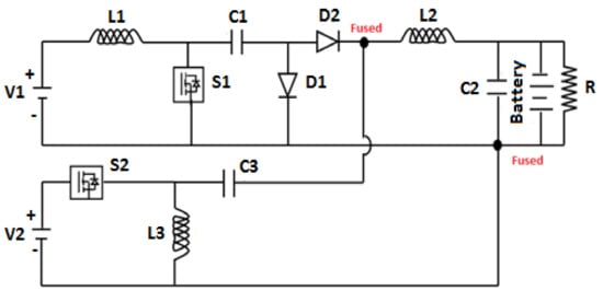
Figure 3.
Circuit topology with the Cuk-Luo integrated converter.
The current, together with voltage, of different functional modes of given Cuk-Luo converters is presented in Figure 4. The relationship existing among voltages, the output and the input for the proposed Cuk-Luo-integrated-based converter can be obtained with the notion of utilizing volt-second balance on the coils L1, L2 and L3. Coil L1 shows that
when applied to coil L3,
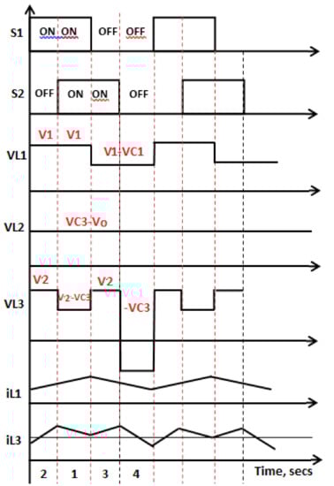
Figure 4.
Various functional modes.
On inductor L2,
By shuffling the various Formulas (3)–(5), the equation is obtained for the output voltage,
where
V1—Solar system voltage
V2—Wind system voltage
d1—Duty cycle 1 (switch S1)
d2—Duty cycle 2 (switch S2).
Figure 5a,b and Figure 6a,b and Table 3 show real-time working demonstrations of different Cuk-Luo converter modes with energy sources of solar-wind systems [,].
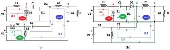
Figure 5.
(a) S1, S2-ON; (b) S1-ON, S2- OFF.
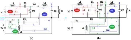
Figure 6.
(a) S1-OFF, S2- ON; (b) S1, S2- OFF.
Table 3.
Demonstration of different modes.
Figure 5a shows the equivalent circuit of (Sw1-ON, Sw2-ON). In this mode, solar power (V1) generates the necessary charge on coil L1, together with the wind voltage (V2), which in turn charges coil L3. As soon as both the switches reach conduction mode, rectifiers D1, D2 should be in reverse conduction mode. Stored charge in the coil L3 is brought back to the load by the battery and charge capacitor C2.
Figure 5b corresponds to the cumulative circuit with Sw1- ON, Sw2-OFF. By the medium of the above image, it can be comprehended that the rectifier D2 is in forward conduction, whereas D1 is in reverse conduction. Primary solar source (V1) powers the coil L1 and the stored energy at capacitor C1; coils L3 and L2 are transferred to the battery and charge capacitor C2, which in turn feeds the telecom load.
Figure 6a corresponds to the cumulative circuit with Sw1- OFF, and Sw2-ON. By the medium of the above image, it can be comprehended that the rectifier D1 is in forward conduction, whereas D2 is in reverse conduction. In addition to this, the energy in coil L1 powers the capacitor C1. The other system, namely the wind, powers coil L3. The energy stored in L2 in turn powers the charge capacitor C2, thereby feeding the load by means of a battery.
The equivalent circuit of Sw1, Sw2-OFF is represented in Figure 6b. As both the switches are in the OFF position, the diodes D1, and D2 are in forward conduction mode. For this mode, the energy stored in coil L1 can be utilized for charging C1. Energy stored in coils L3 and L2 in turn power the battery and the charge capacitor C2 directed to feed the load.
The power dissipation of the proposed Cuk-Luo converter is 1164 watts and the power obtained is 1200 watts. Therefore, the efficiency is calculated as 97%. The efficiency of conventional Cuk and SEPIC separate converters and the proposed Cuk-SEPIC fused converter are 80% and 96%, respectively []. The efficiency of Cuk-buck and improved Cuk-buck converters [] are 83.38% and 92.69%, respectively. Thus, it can be concluded that the Cuk-Luo fused converter is more efficient.
3.3. Embedded Controller Design Procedure for the Cuk-Luo Integrated Converter
The detailed logic flow chart is shown in Figure 7.
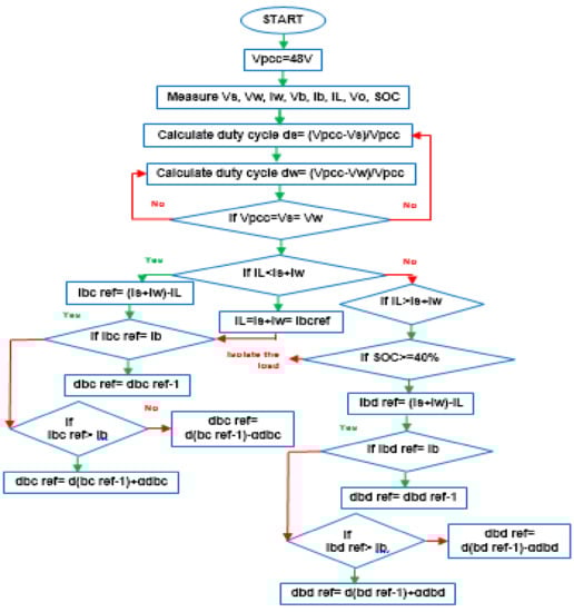
Figure 7.
Detailed logic of proposed embedded-based controller.
For the present system, the smart controller with power management gathers the instantaneous current (battery current IB, state of charge SOC, IS, IW), together with the voltage (VW, battery voltage VB, VS) of numerous sources of inputs. According to the gathered data, controller signals choose the duty cycle width gate pulses (dS, dW), discharging and charging battery duty cycles (dbc, dbd). It is utilized for developing intersections with voltages at a common coupling VPCC = −48V, as per Equations (7) and (8) for wind and solar energy sources,
and
where
VPCC—Common coupling voltage
VS—Cuk converter input voltage when connected to the solar system
VW—Luo converter input voltage when connected to the wind system.
For any deviation in the Vpcc from −48 V, the input sources connected to the converter are aligned through the correction of duty cycles. As soon as Vpcc is assigned with −48 V, the controller estimates the load current with the directed wind and solar input currents. If the input current is lower than the load current, the Ibcref becomes congruent with the excess power available at Vpcc and it is estimated as follows.
where
(ISref + Iwref) − IL = IBcref,
ISref—Reference solar current
IWref—Reference wind current
IL—Load voltage
IBCref—Reference battery charging current.
Once we reach the BC phase, the energy needed for the load becomes lesser than the extracted energy, which in turn leads to power delivery at the receiving end of 𝑉𝑂 up to 𝑉𝐻. Post reaching 𝑉𝐻, excess extracted residual energy can be used to power the battery by means of an integral-based charging method, which powers the battery until the current in the coil is exhausted.
As soon as the generated power becomes insufficient enough to direct it to the receiving end, the battery drains with its duty cycle of dbd. The design of the controller makes its discharge possible only if the SOC (state of charge) is found to be above 40%. The calculation for the discharging reference current is
where:
IL − (ISref + IWref) = IBdref,
IBcref—Reference battery discharging current.
Even after this demand at the receiving end is large, the load should be taken off from the supply.
3.3.1. Battery Specifications
The SOC (state of charge) with a 24 V charging and discharging battery method is found from the battery current and voltage (battery hand book).
Table 4a,b show the voltage present at the end of different discharging and charging currents for a lead acid battery with a terminal voltage of 24 V. The SOC is estimated using the formula
where
V—Voltage of the battery
C—Capacity of the battery
V1—Values of voltage being lesser than the terminal or end voltage for each column with a current value
V2—Values of voltage being higher than the terminal or end voltage for each column with a current value
A—V1 row SOC reference
B—V2 row SOC reference.
In addition, the determination of the state of charge while discharging can be estimated from the discharge data using the above-mentioned procedure.
Table 4.
(a) Battery charging currents; (b) battery discharging currents.
Table 4.
(a) Battery charging currents; (b) battery discharging currents.
| (a) | |||||
|---|---|---|---|---|---|
| SOC | At Charging | ||||
| Voltage at (C/15) | Voltage at (C/30) | Voltage at (C/50) | Voltage at (C/75) | ||
| 10 | 22.5 | 22 | 21.4 | 21 | |
| 20 | 22.32 | 22.21 | 22.1 | 22 | |
| 30 | 22.63 | 22.4 | 22.3 | 22.2 | |
| 40 | 22.92 | 22.5 | 22.45 | 22.42 | |
| 50 | 23.98 | 23.25 | 23.2 | 23.1 | |
| 60 | 23.52 | 23.5 | 23.4 | 23.3 | |
| 70 | 23.74 | 23.63 | 23.61 | 23.5 | |
| 80 | 24 | 23.9 | 23.7 | 23.6 | |
| 90 | 24.24 | 24.13 | 24.12 | 24.24 | |
| 100 | 24.46 | 24.2 | 24.15 | 24.1 | |
| (b) | |||||
| SOC | At discharging | ||||
| Voltage at (C/15) | Voltage at (C/30) | Voltage at (C/50) | Voltage at (C/75) | Voltage at (C/150) | |
| 10 | 24 | 22.6 | 21.23 | 21.22 | 21.2 |
| 20 | 23.2 | 22.82 | 22.8 | 22.7 | 22 |
| 30 | 23.3 | 23.2 | 23 | 22.9 | 22.4 |
| 40 | 23.6 | 23.4 | 23.3 | 23.2 | 22.6 |
| 50 | 23.7 | 23.5 | 23.4 | 23.3 | 22.8 |
| 60 | 24.2 | 23.9 | 23.6 | 23.5 | 22.9 |
| 70 | 24.4 | 24.4 | 24.2 | 23.9 | 23 |
| 80 | 24.8 | 24.45 | 24.3 | 24.2 | 23.2 |
| 90 | 25 | 24.6 | 24.4 | 24.3 | 23.3 |
| 100 | 25.2 | 24.8 | 24.5 | 23.4 | 23.6 |
3.3.2. Battery Operation
The modes of operation for any devices utilized as a storage medium (battery) is discussed as follows. The net energy of the proposed system is the difference among load demand in any instant of time and the net output energy.
where
Enet(t) = Eg(t) − EL(t),
Enet(t)—Net energy generated
Eg(t)—Energy generated through renewable energy sources
EL(t)—Estimated load demand.
Mode 1
In this mode, the energy level of the battery bank is equal to its previous hour energy level as the net energy developed from wind-solar hybrid medium can be estimated to be zero.
The estimated load can be supplied by the previous hour energy stored in the battery.
where
Esupplied Load (t) = Edisch(t),
ELoad supplied (t)—Load supplied
Edisch(t)—Battery discharging energy.
Mode 2
For this mode, the cumulative input energy extracted from the wind-solar hybrid system can be found to be greater than the total power demand. The excess energy Ech(t) generated to power the battery through buck converter (Figure 1) is.
where
Ech(t) = Eg(t) − EL(t),
Ech (t)—Battery charging energy.
Mode 3
If the energy generated by the wind-solar hybrid medium exceeds the load demand and the largest battery storage, this leads to a greater energy being disposed through the dump load.
Mode 4
In this mode, the output energy extracted from solar-wind hybrid medium can be insufficient in order to feed the required demand of load; then the battery power is compensated for supplying power through the boost converter (Figure 1). It is written as
E ch(t) = EL(t) − Eg(t).
Mode 5
For this mode, the output energy extracted from hybrid solar-wind systems is lesser than the battery energy level and the load demand is at the lowest level; then the load is disconnected.
4. Simulation Results and Discussion
Analysis for the designated integrated Cuk-Luo-based converter is analyzed using simulation from MATLAB.
MATLAB simulation for the proposed circuit is carried out using the constraints L1 of 158 μH, L2 of 1808 μH, L3 of 158 μH, C1 of 1389 μF, C2 of 1545 μF, C3 of 407 μF, R=1.32 Ω and a switching frequency of 20 kHz to analyze the system. The generated power was obtained from the regulation parameters of 48 V/23 A/1.2 kW. Figure 8 shows the output current and voltage from the waveforms of the Cuk-Luo DC-DC converter powering the telecom load.
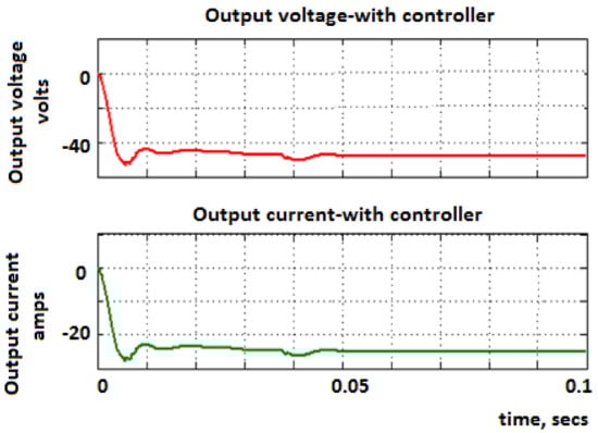
Figure 8.
Final output voltage and current.
Figure 9 depicts the highest current and voltage from the S1 and S2 switching device. Conduction losses and switching losses from switches Sw1 and Sw2 are estimated from 100 W and 1.48 W, and 30 W and 0.007 W, respectively. The copper losses of the coils L1, L2 and L3 and storage capacitors C1, C2 and C3 are found as 5.52 W, 4.69 W, 0.24 W and 123 W, 26.8 W, 26.85 W, respectively.
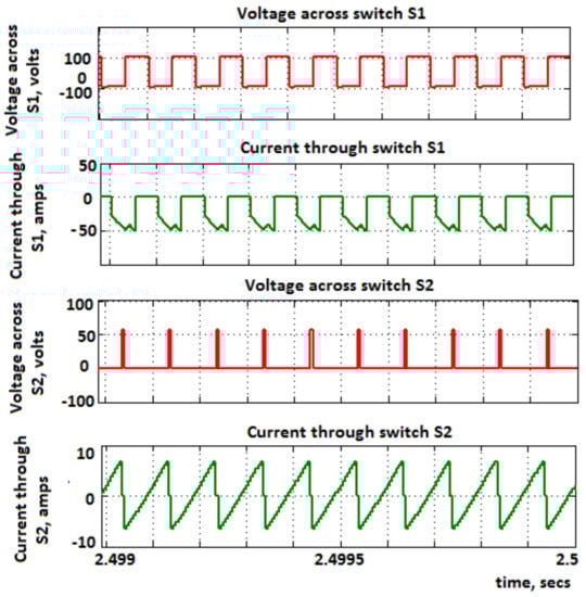
Figure 9.
Final switch voltages and currents of S1 and S2.
Figure 10a,b give the voltage across the capacitors C1 and C3 and coils L1, L2 and L3. The performance of the Cuk-Luo-based converter can be estimated to be 91%. Thus, the integrated converter implemented from wind-solar mediums have a higher level of performance. The SOC estimation, battery current and voltage can be measured from the embedded-based controller.
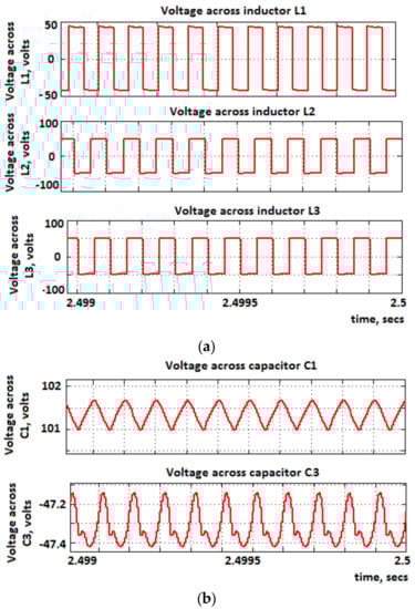
Figure 10.
(a) Voltage across inductors L1, L2 and L3; (b) voltage across capacitors C1 and C3.
Figure 11a depicts the estimated waveforms obtained from the designed controller. Using the current from the battery, the excess power obtained can be reverted back to the battery from the opposite direction. For duty cycles dS, dW, dbc and dbd, the controller performances are shown in Figure 11b.
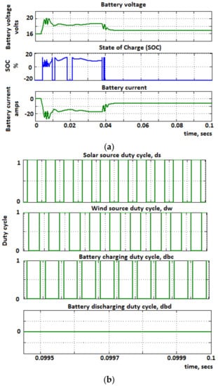
Figure 11.
(a) Battery voltage, final SOC and battery current; (b) final duty cycles.
5. Prototype Implementation
The prototype model for the given integrated Cuk-Luo-based converter has been designed utilizing a FPGA controller with a couple of DC sources. Table 5 depicts the numerical values utilized for the implementation process for Cuk-Luo topology. The low-key pulses manifested through the FPGA controller can be utilized as a trigger for MOSFET-type switches. Figure 12 depicts the prototype design for the Cuk-Luo integrated strategy utilizing a FPGA controller.
Table 5.
Hardware component values.
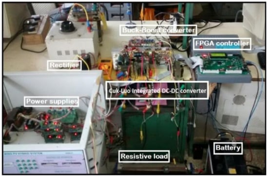
Figure 12.
Demonstration of the hardware setup of the Cuk-Luo converter having variable DC input sources.
Field Programmable Gate Arrays (FPGA) and Cyclone-IV EEP4CE0F484 were known to be reprogrammable logic devices and majorly flexible. As demonstrations of peripherals and processors, Xilinx FPGAs suggests they are completely user-programmable.
The proposed embedded controller for the Cuk-Luo converter is implemented utilizing a ML605 controller board along with a XC6VLX240T-1FFG1156 array. It gives the gate arrays with an option of being linked with the Simulink mode. Hardware demonstration is developed to approve the overall structure on the ML605 controller with the XC6VLX240T-1FFG1156 array. Running the board onto the PC will close the loop. The Xilinx ISE application gives the file in bit format which can be loaded to the required array by means of connection using JTAG.
In the present literature, pulses from the gate are obtained from the FPGA-based controller array. It has an undue advantage of a higher efficiency at a reasonable rate of economy. The input voltages are maintained at V1 = 54 V and V2 = 55 V. Figure 13a depicts the hardware results of the output voltage and current. The measured voltage and current from the hardware are 48 V and 2.18 A, respectively. Figure 13b presents the switching pulses of Sw1 and Sw2. Figure 14 depicts the battery current and voltage. It can be noted that the obtained battery voltage and current is 22.9 V and 4.68 A, respectively.
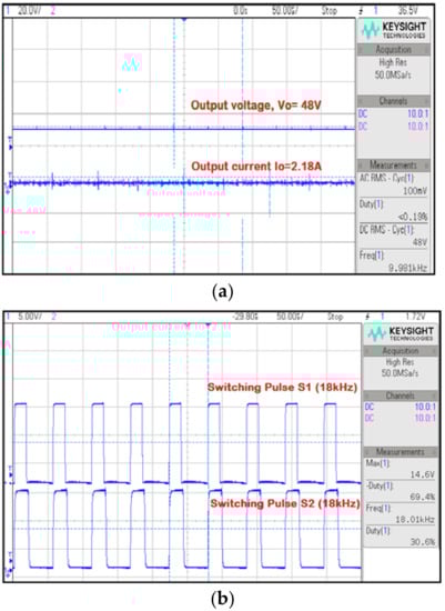
Figure 13.
(a) Output voltage and output current; (b) switching pulses.
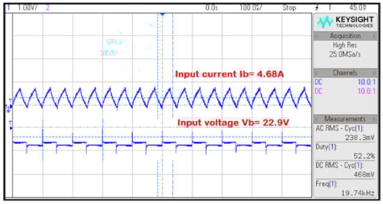
Figure 14.
Battery current and voltage.
From Figure 15, it is clear that the input currents are 2.65 A and 4.17 A and the output current is 4.17 A. Therefore, the cumulative remaining current can be employed for powering the battery, which gives a current of 2.07 A.
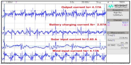
Figure 15.
Battery charging current.
6. Conclusions
An integrated Cuk-Luo DC-DC-based converter network having hybrid solar-wind energy system for applications of telecom network powering is verified and proposed in the present literature. It should be able to supply the load independently or simultaneously, based on the presence of any input energy sources. Resulting circuits offer a comparatively lower cost since it gives increased performance at reduced component parts. The management of energy has been programmed using the algorithm in order to consistently make the power at equal levels from the PCC point, which in turn leads to making the reference currents regulate, depending upon the instantaneous power which can be supplied by load and source requirements. Any storage device such as a battery can be used as a backup for the present work. Instantaneous determination of the state of charge, discharging and charging of batteries directed to a known sink or source of the power input, which can be based on the load demand, is presented.
Author Contributions
Conceptualization, B.S.N. and M.C.; methodology, B.S.N.; software, M.C.; validation, S.T., A.A.A.A. and B.S.N.; formal analysis, S.T. and M.A.; investigation, A.A.A.A., and M.A.; resources, M.A.M.; data curation, S.T.; writing—original draft preparation, B.S.N.; writing—review and editing, M.C.; visualization, M.A.M.; supervision, M.A.K.; project administration, M.A.K.; funding acquisition, A.A.A.A. and M.A. All authors have read and agreed to the published version of the manuscript.
Funding
Taif University Researchers Supporting Project number (TURSP-2020/121), Taif University.
Data Availability Statement
Not applicable.
Acknowledgments
The authors would like to acknowledge the support received by Taif University Researchers Supporting Project number (TURSP-2020/121), Taif University, Taif, Saudi Arabia.
Conflicts of Interest
The authors declare no conflict of interest.
References
- Naziruddin, N.; Abdurahman, F.; Radhiah, R.; Maimun, M.; Bakar, S.A. Design and Implementation of Substitution Power Supply at Base Transceiver Station (BTS) Using Hybrid Distributed Generator Wind Turbine and Solar Cell Powers. Sci. J. PPI-UKM 2017, 4, 70–75. [Google Scholar]
- Ahmed, F.; Naeem, M.; Ejaz, W.; Iqbal, M.; Anpalagan, A.; Kim, H.S. Renewable Energy Assisted Traffic Aware Cellular Base Station Energy Cooperation. Energies 2018, 11, 99. [Google Scholar] [CrossRef]
- Bhattacharya, D.; Kumar, T. Modeling and Control of a Solar/Wind Hybrid Energy System for BTS. Int. J. Appl. Eng. Res. 2014, 9, 11621–11630. [Google Scholar]
- Kumar, K.S.; Bhaskar, G.; Raghaveder, C. Power Management of Cell Sites. Int. Refereed J. Eng. Sci. (IRJES) 2013, 2, 41–45. [Google Scholar]
- Hossam, K.; Mikhail, A.R.; Hafez, I.M.; Anis, W.R. Optimum Design of PV Systems for BTS in Remote and Urban Areas. Int. J. Sci. Technol. Res. 2016, 5, 1–9. [Google Scholar]
- Joga Rao, G.; Shrivastava, S.K.; Ranjith, V.L. Analysis and simulation of hybrid solar- wind renewable energy systems. Int. J. Innov. Res. Electr. Electron. Instrum. Control Eng. 2016, 4, 33–38. [Google Scholar]
- Pandiyan, P.; Sitharthan, R.; Saravanan, S.; Prabaharan, N.; Ramji Tiwari, M.; Chinnadurai, T.; Yuvaraj, T.; Devabalaji, K.R. A comprehensive review of the prospects for rural electrification using stand-alone and hybrid energy technologies. Sustain. Energy Technol. Assess. 2022, 52, 102155. [Google Scholar] [CrossRef]
- Manikandan, A.; Vadivel, N. Design and implementation of luo converter for electric vehicle applications. Int. J. Eng. Trends Technol. (IJETT) 2013, 4, 4437–4441. [Google Scholar]
- Taylor, P.; Aravind, C.K.; Ilango, G.S.; Nagamani, C.; Jaya Bharata Reddy, M. A control strategy for hybrid autonomous power system with a battery management scheme. Electr. Power Compon. Syst. 2015, 43, 37–41. [Google Scholar]
- He, Y.; Luo, F.L. Analysis of Luo converters with voltage-lift circuit. IEEE Proc. -Electr. Power Appl. 2005, 152, 1239–1252. [Google Scholar] [CrossRef]
- Rashid, M.H. Power Electronics Handbook; Butterworth-Heinemann: Oxford, UK, 2017. [Google Scholar]
- Mengi, O.O.; Altas, I.H. A New energy management technique for PV/wind/grid renewable energy system. Int. J. Photo Energy Hindawi Publ. Corp. 2015, 2015, 1–20. [Google Scholar] [CrossRef]
- Almi, M.F.; Arrouf, M.; Belmili, H.; Boulouma, S.; Bendib, B. Energy management of wind/PV and battery hybrid system. Int. J. New Comput. Archit. Appl. (IJNCAA) 2014, 4, 30–38. [Google Scholar] [CrossRef]
- Zarrad, O.; Hajjaji, M.A.; Jemaa, A.; Mansouri, M.N. Sizing Control and Hardware Implementation of a Hybrid Wind-Solar Power System, Based on an ANN Approach, for Pumping Water. Int. J. Photo Energy Hindawi Publ. Corp. 2019, 2019, 1–15. [Google Scholar] [CrossRef]
- Shrivastava, A.; Calhoun, B.H. Modelling DC-DC converter efficiency and power management in ultralow power systems. In Proceedings of the IEEE Subthreshold Microelectronics Conference (SubVT), Waltham, MA, USA, 9–10 October 2012; pp. 1–3. [Google Scholar]
- Ayang, A.; Ngohe-Ekam, P.S.; Videme, B.; Temga, J. Power consumption: Base stations of telecommunication in sahel zone of cameroon: Typology based on the power consumption—Model and energy savings. J. Energy Hindawi Publ. Corp. 2016, 2016, 3161060. [Google Scholar] [CrossRef]
- Chandrasekar, B.; Nallaperumal, C.; Dash, S.S. A nonisolated three-port DC–DC converter with continuous input and output currents based on Cuk topology for PV/fuel cell applications. Electronics 2019, 8, 214. [Google Scholar] [CrossRef]
- Thayumanavan, P.; Kaliyaperumal, D.; Subramaniam, U.; Bhaskar, M.S.; Padmanaban, S.; Leonowicz, Z.; Mitolo, M. Combined Harmonic Reduction and DC Voltage Regulation of A Single DC Source Five-Level Multilevel Inverter for Wind Electric System. Electronics 2020, 9, 979. [Google Scholar] [CrossRef]
- Alavi, O.; Rajabloo, T.; De Ceuninck, W.; Daenen, M. Non-Isolated DC-DC Converters in Fuel Cell Applications: Thermal Analysis and Reliability Comparison. Appl. Sci. 2022, 12, 5026. [Google Scholar] [CrossRef]
- Mahafzah, K.A.; Obeidat, M.A.; Al-Shetwi, A.Q.; Ustun, T.S. A Novel Synchronized Multiple Output DC-DC Converter Based on Hybrid Flyback-Cuk Topologies. Batteries 2022, 8, 93. [Google Scholar] [CrossRef]
- Khan, H.R.; Kazmi, M.; Ashraf, H.B.; Hashir Bin Khalid, M.; Hasan, A.; Qazi, S.A. An Isolated Power Factor Corrected Cuk Converter with Integrated Magnetics for Brushless DC Ceiling Fan Applications. Electronics 2021, 10, 1720. [Google Scholar] [CrossRef]
- Priyadarshi, N.; Bhaskar, M.S.; Azam, F.; Singh, M.; Dhaked, D.K.; Taha, I.B.; Hussien, M.G. Performance Evaluation of Solar-PV-Based Non-Isolated Switched-Inductor and Switched-Capacitor High-Step-Up Cuk Converter. Electronics 2022, 11, 1381. [Google Scholar] [CrossRef]
- Haider, Z.; Ulasyar, A.; Khattak, A.; Zad, H.S.; Mohammad, A.; Alahmadi, A.A.; Ullah, N. Development and Analysis of a Novel High-Gain CUK Converter Using Voltage-Multiplier Units. Electronics 2022, 11, 2766. [Google Scholar] [CrossRef]
- Jegha, A.; Darcy, G.M.S.P.; Nallapaneni, M.K.S.; Ghosh, A. Optimally tuned interleaved Luo converter for PV array fed BLDC motor driven centrifugal pumps using whale optimization algorithm—A resilient solution for powering agricultural loads. Electronics 2020, 9, 1445. [Google Scholar] [CrossRef]
- Chincholkar, S.H.; Malge, S.V.; Patil, S.L. Design and analysis of a voltage-mode non-linear control of a non-minimum-phase positive output elementary Luo converter. Electronics 2022, 11, 207. [Google Scholar] [CrossRef]
- Gholizadeh, H.; Shahrivar, R.S.; Hashemi, M.R.; Afjei, E.; Gorji, S.A. Design and implementation a single-switch step-up DC-DC converter based on cascaded boost and luo converters. Energies 2021, 14, 3584. [Google Scholar] [CrossRef]
- Margaret Amutha, W.; Harshini, H.; Rajini, V. A new green energy interface for telecommunications. Int. J. Electron. 2018, 105, 1831–1854. [Google Scholar] [CrossRef]
- Amutha, W.; Margaret, V.R.; Rajini, V. A novel parallel power conversion technique for efficiency improvement in hybrid DC/DC converter based rural telephony. In Proceedings of the 2013 International Conference on Renewable Energy and Sustainable Energy (ICRESE), Coimbatore, India, 5–6 December 2013; IEEE: Piscataway, NJ, USA, 2013; pp. 64–69. [Google Scholar]
- Roumila, Z.; Rekioua, D.; Rekioua, T. Energy management based fuzzy logic controller of hybrid system wind/photovoltaic/diesel with storage battery. Int. J. Hydrog. Energy 2017, 42, 19525–19535. [Google Scholar] [CrossRef]
- Bendary, A.F.; Ismail, M.M. M.M. Battery Charge Management for Hybrid PV/Wind/Fuel Cell with Storage Battery. Energy Procedia 2019, 162, 107–116. [Google Scholar] [CrossRef]
- Schimpe, M.; Becker, N.; Lahlou, T.; Holger, C.; Hesse, A.J. Energy efficiency evaluation of grid connection scenarios for stationary battery energy storage systems. Energy Procedia 2018, 155, 77–101. [Google Scholar] [CrossRef]
- Ibrahim, H.; Anani, N. Variations of PV module parameters with irradiance and temperature. Energy Procedia 2017, 134, 276–285. [Google Scholar] [CrossRef]
- Chong, L.W.; Wong, Y.W.; Rajkumar, R.K.; Isa, D. Modelling and Simulation of Standalone PV Systems with Battery super capacitor Hybrid Energy Storage System for a Rural Household. Energy Procedia 2016, 107, 232–236. [Google Scholar] [CrossRef]
- Barta, G.; Pasztor, B.; Prava, V. Optimized Charge Controller Schedule in Hybrid Solar-Battery Farms for Peak Load Reduction. Energies 2021, 14, 7794. [Google Scholar] [CrossRef]
- Munzke, N.; Schwarz, B.; Hiller, M. Intelligent control of household Li-ion battery storage systems. Energy Procedia 2018, 155, 17–31. [Google Scholar] [CrossRef]
- Gajewski, P.; Pieńkowski, K. Control of the Hybrid Renewable Energy System with Wind Turbine, Photovoltaic Panels and Battery Energy Storage. Energies 2021, 14, 1595. [Google Scholar] [CrossRef]
- Znaczko, P.; Szczepanski, E.; Kaminski, K.; Chamier-Gliszczynski, N.; Kukulski, J. Experimental diagnosis of the heat pipe solar collector malfunction. A case study. Energies 2021, 14, 3050. [Google Scholar] [CrossRef]
- Tasmin, N.; Farjana, S.H.; Hossain, M.R.; Golder, S.; Parvez Mahmud, M.A. Integration of Solar Process Heat in Industries: A Review. Clean Technol. 2022, 4, 97–131. [Google Scholar] [CrossRef]
- Uzhytchak, M.; Smolková, B.; Lunova, M.; Jirsa, M.; Frtús, A.; Kubinová, Š.; Dejneka, A.; Lunov, O. Iron oxide nanoparticle-induced autophagic flux Is regulated by interplay between p53-mTOR axis and Bcl-2 signaling in hepatic cells. Cells 2020, 9, 1015. [Google Scholar] [CrossRef]
- Jafari, S.; Sohani, A.; Hoseinzadeh, S.; Pourfayaz, F. The 3E Optimal Location Assessment of Flat-Plate Solar Collectors for Domestic Applications in Iran. Energies 2022, 15, 3589. [Google Scholar] [CrossRef]
Disclaimer/Publisher’s Note: The statements, opinions and data contained in all publications are solely those of the individual author(s) and contributor(s) and not of MDPI and/or the editor(s). MDPI and/or the editor(s) disclaim responsibility for any injury to people or property resulting from any ideas, methods, instructions or products referred to in the content. |
© 2023 by the authors. Licensee MDPI, Basel, Switzerland. This article is an open access article distributed under the terms and conditions of the Creative Commons Attribution (CC BY) license (https://creativecommons.org/licenses/by/4.0/).