
Design of a High Torque Density Robot Joint and Analysis of Force Control Method Applied for a Light Exoskeleton


Abstract
:1. Introduction
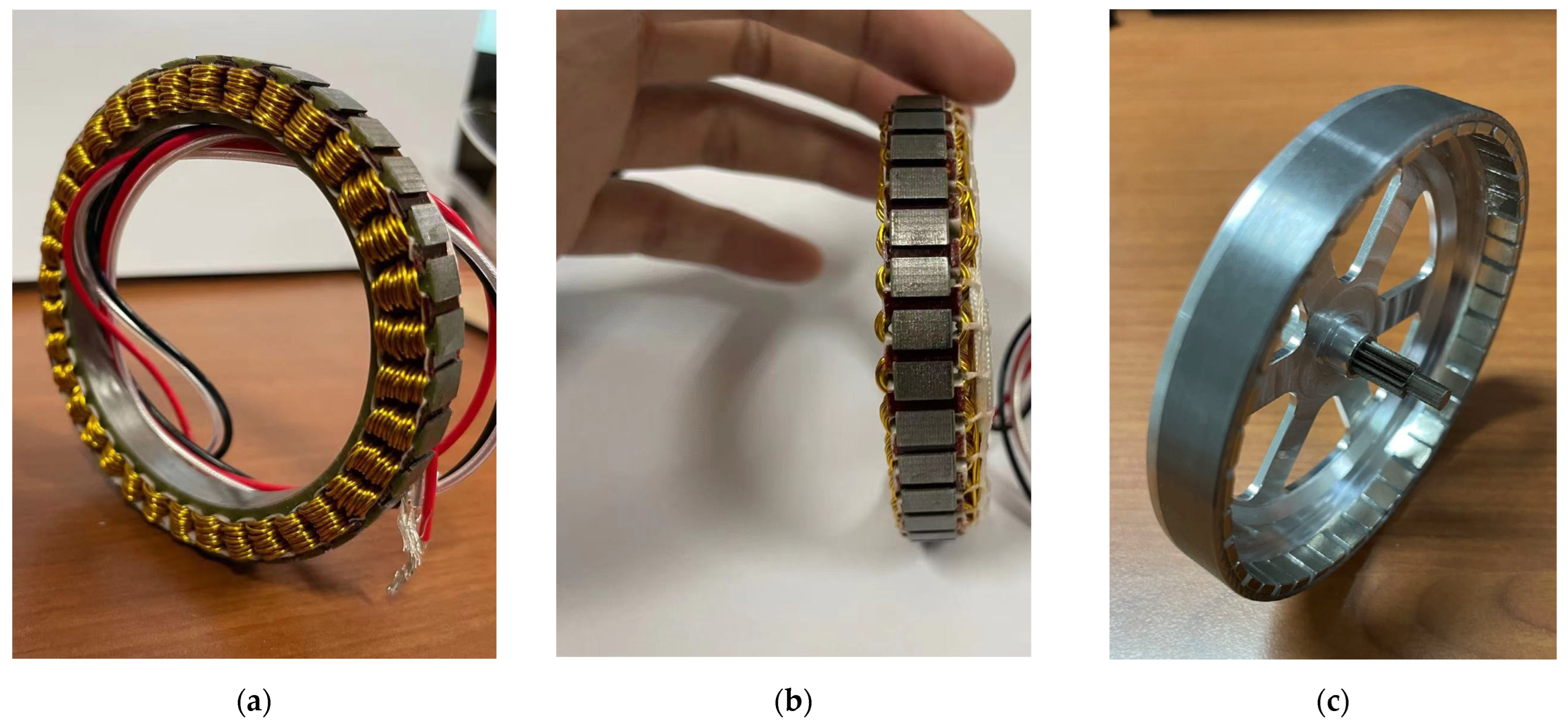
2. Prototype Design
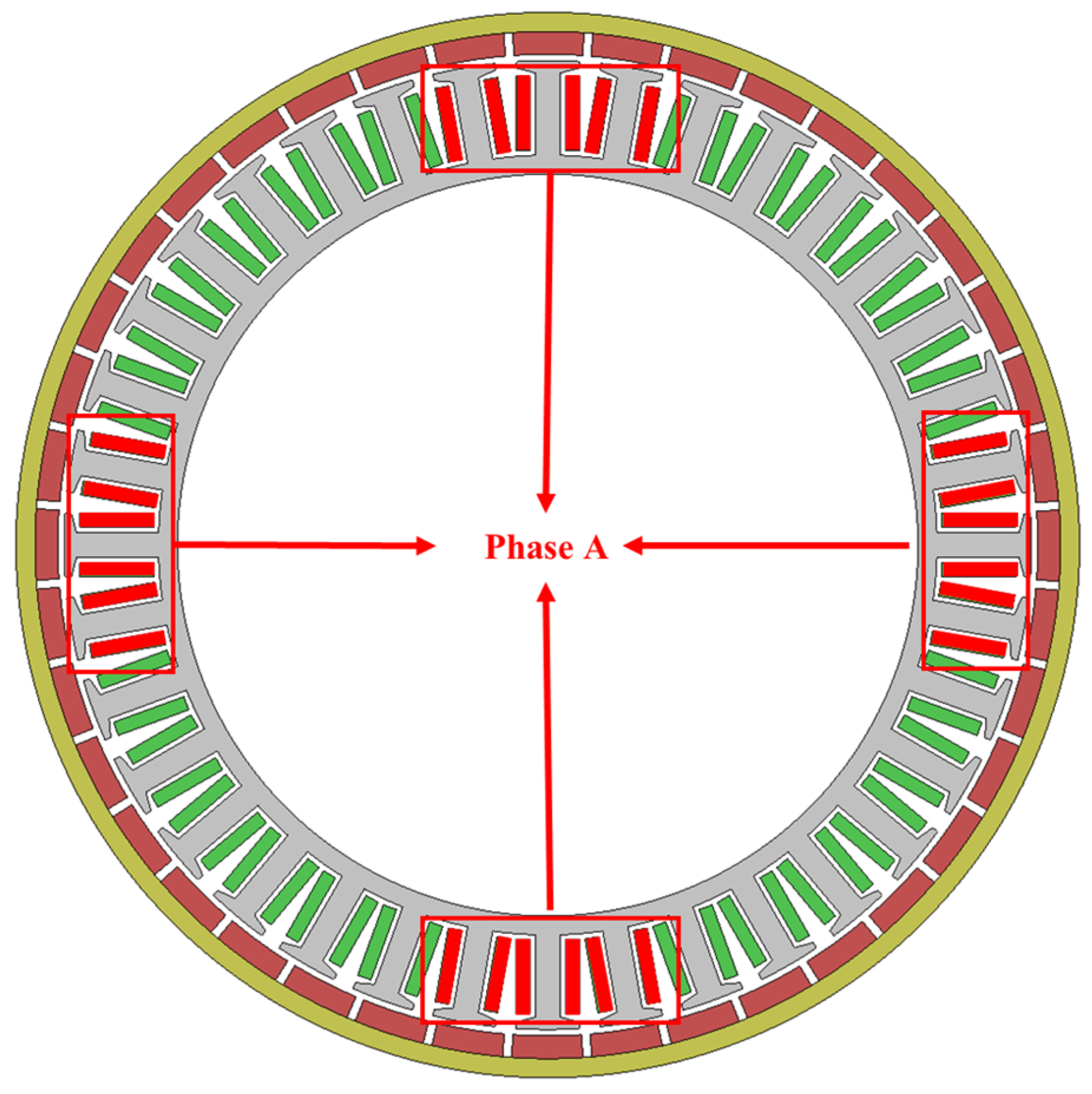
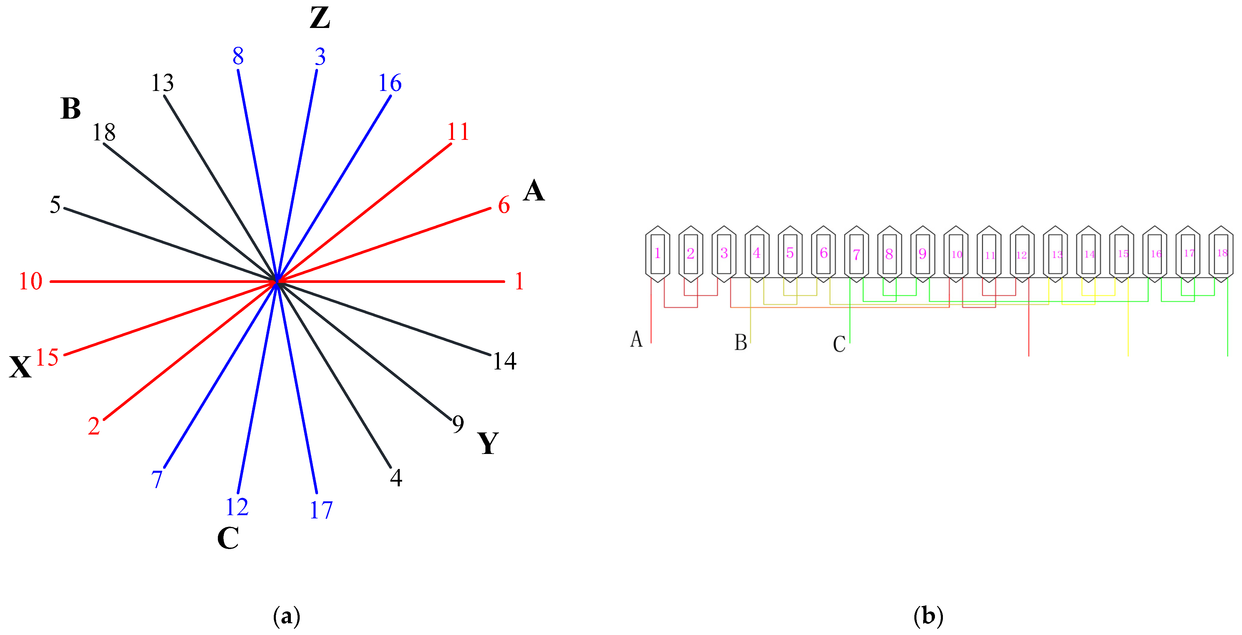
2.1. Slot–Pole Combination of the Motor
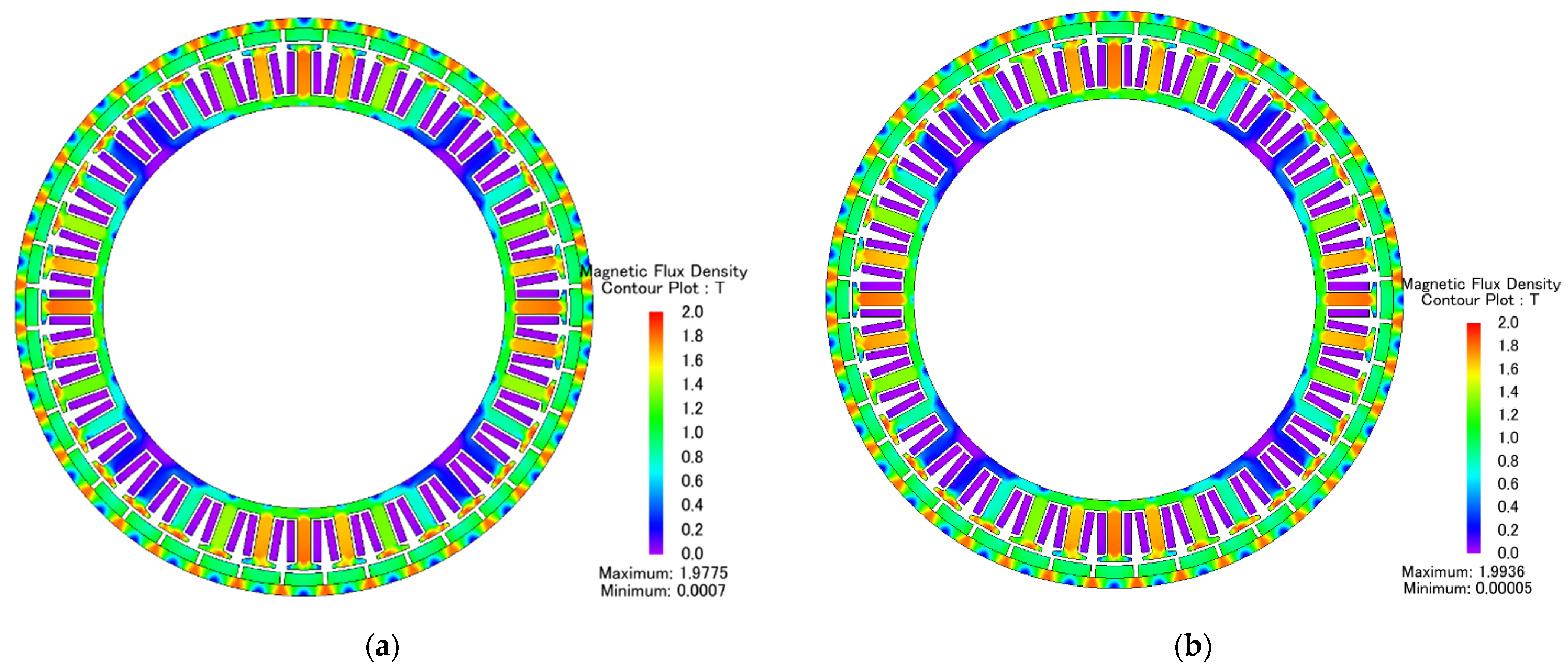
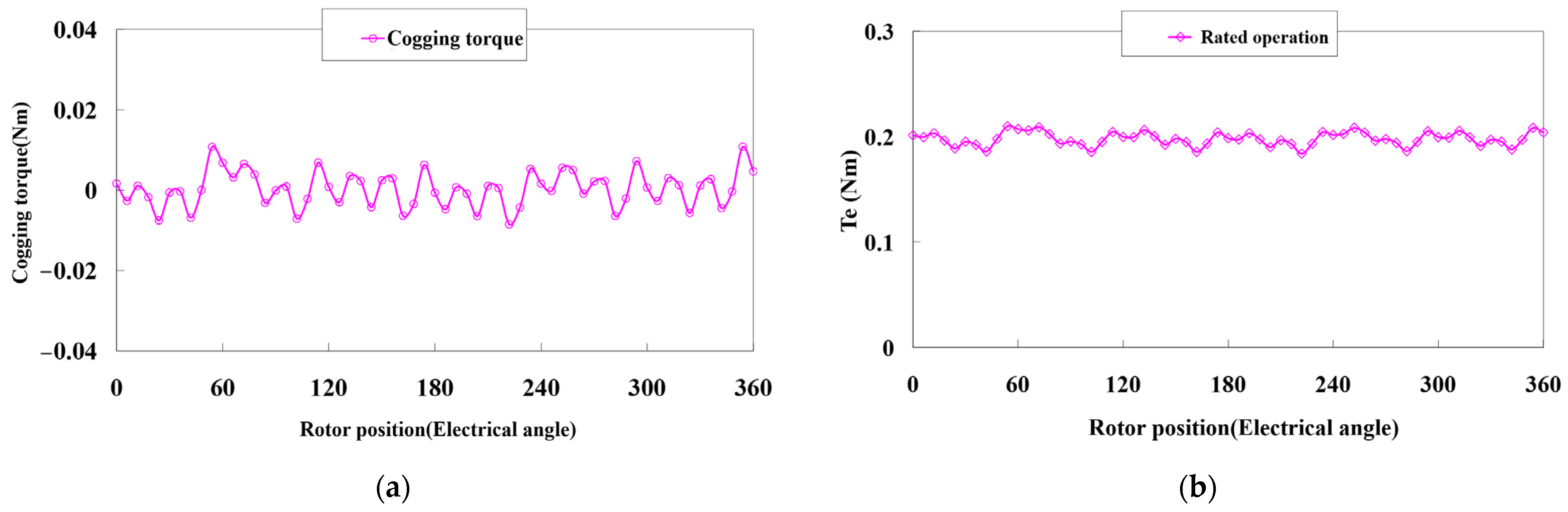
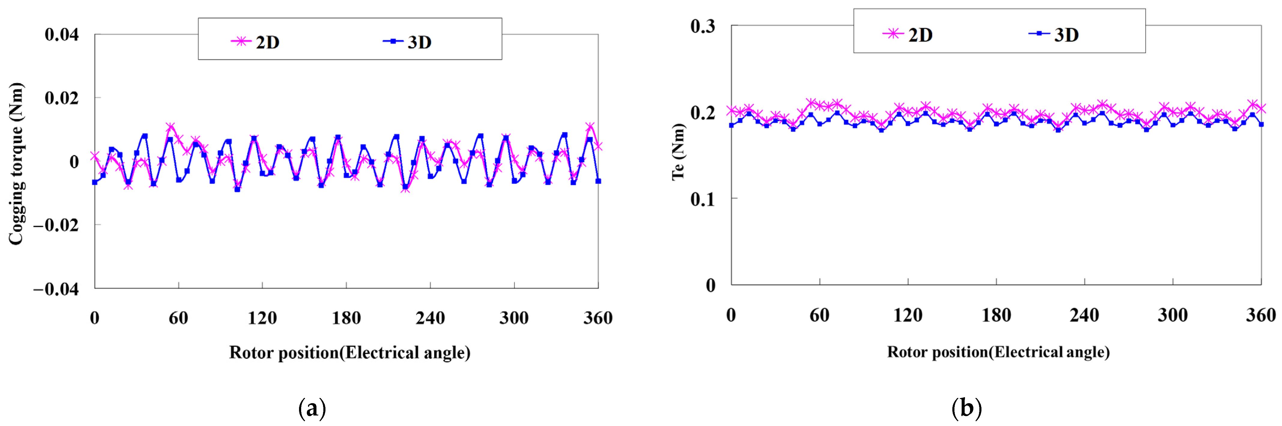
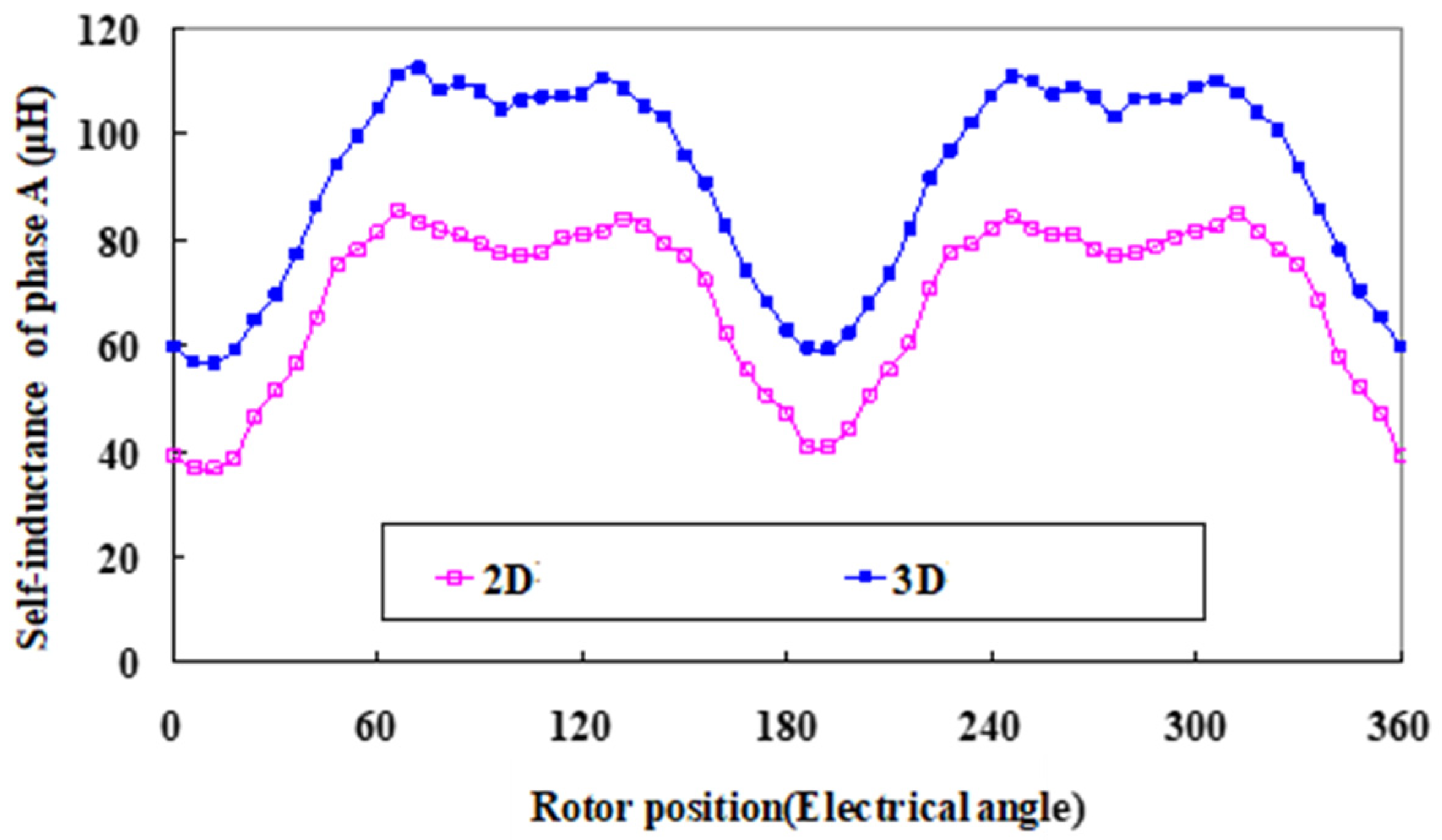
2.2. 2D FEA Results
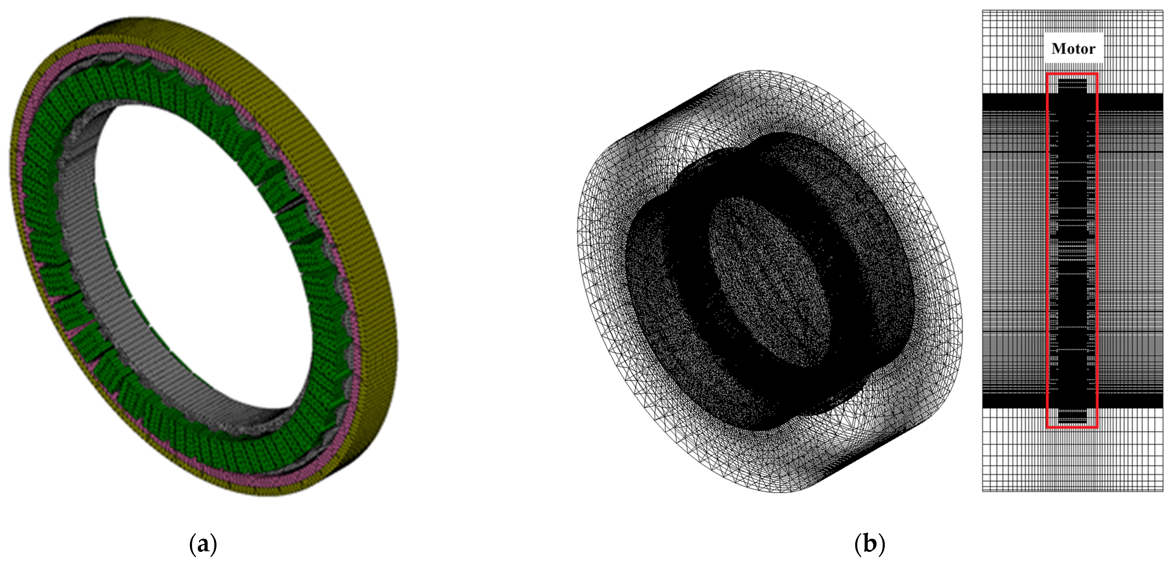
2.3. 3D FEA Results
2.4. Overload Capacity
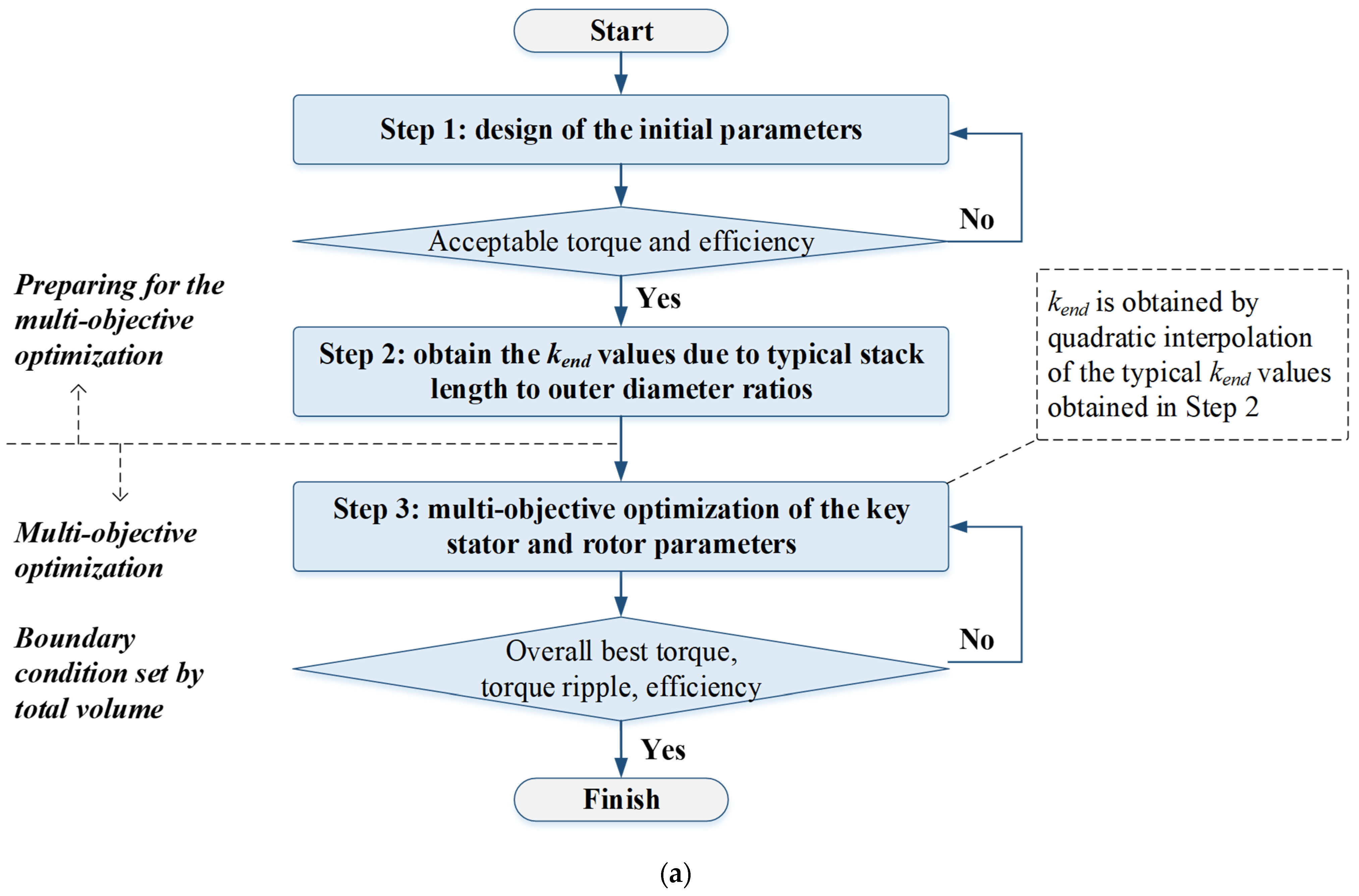
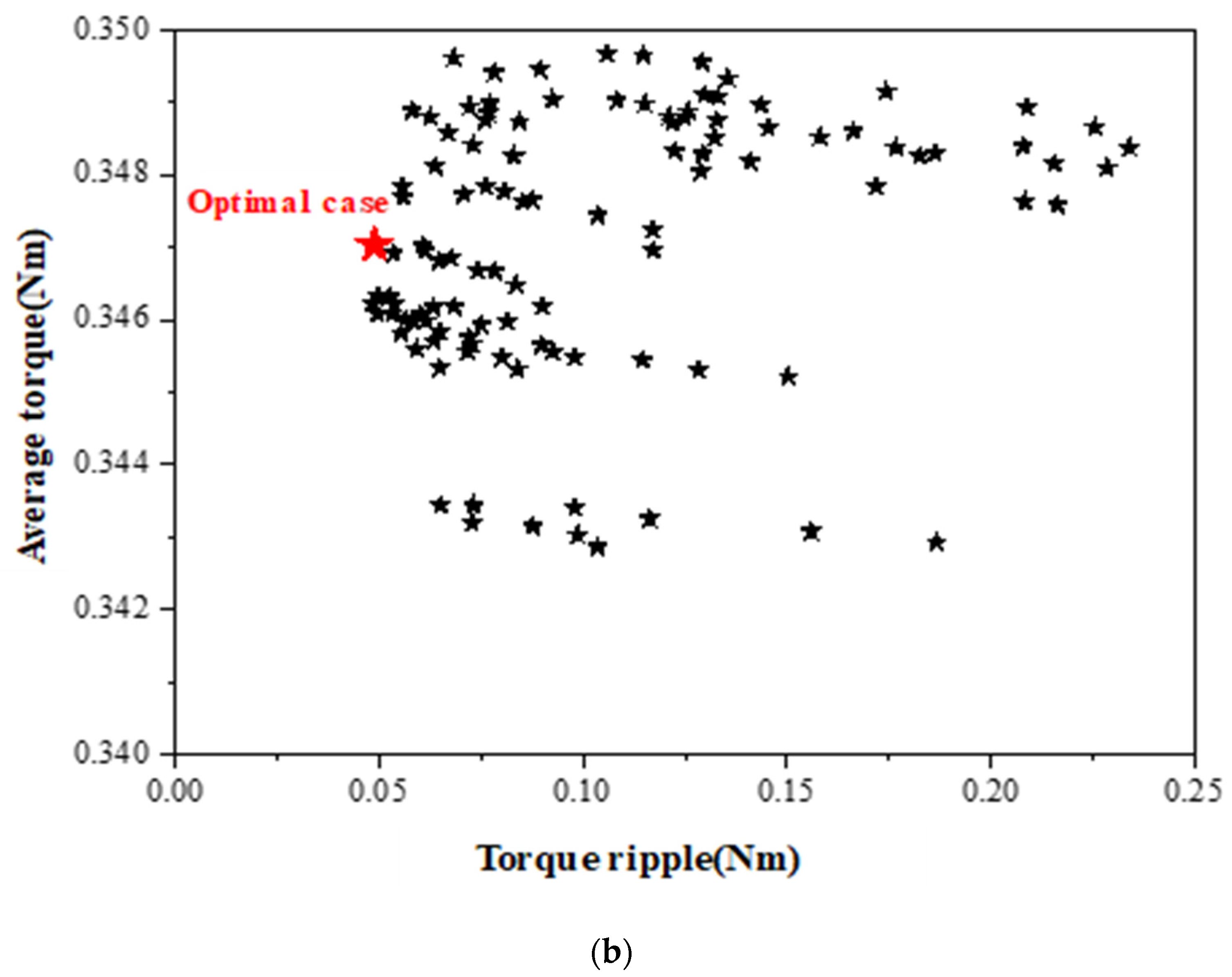
2.5. Parameter Optimization of the Motor
2.6. Recuder Design
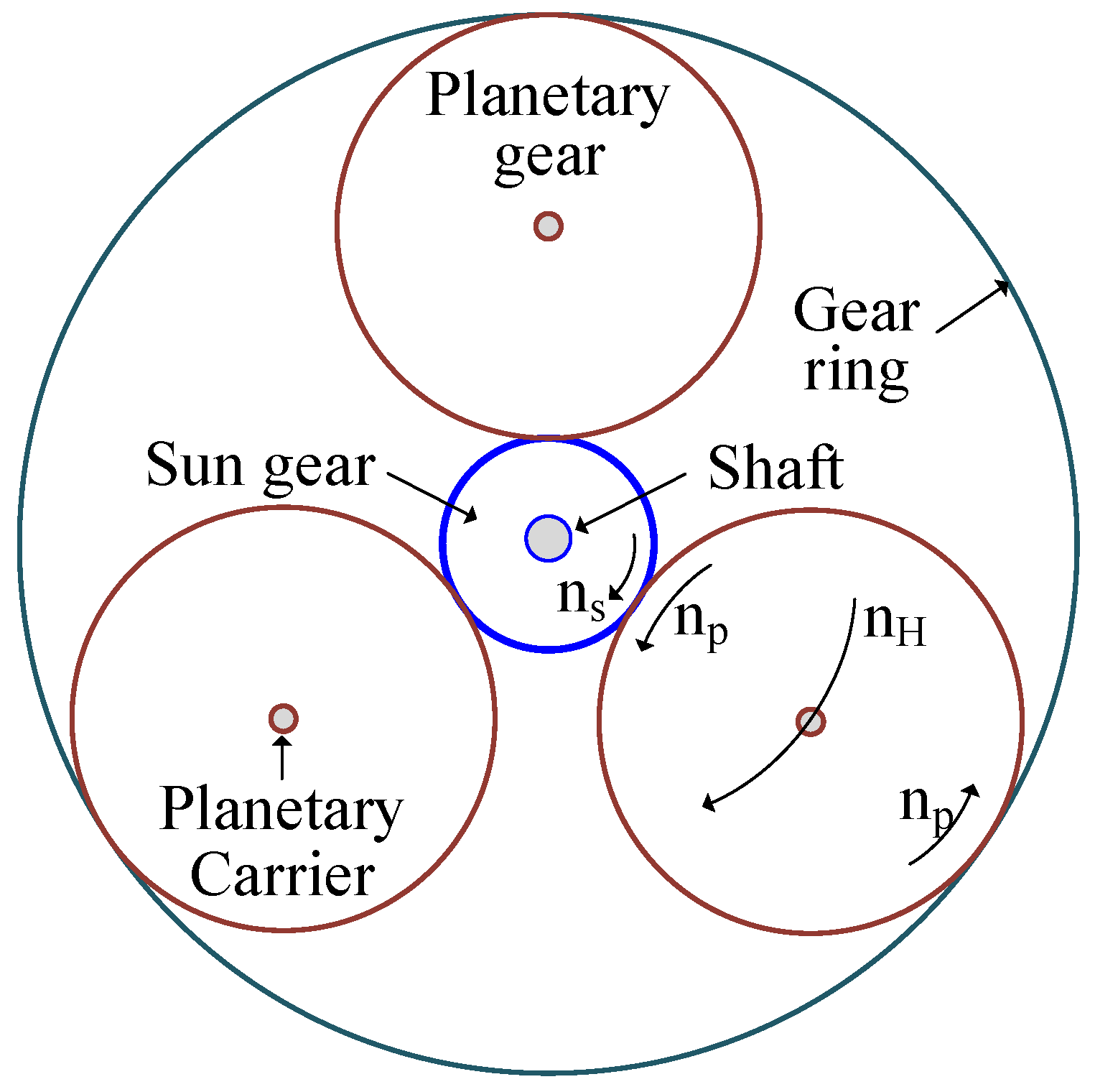
2.6.1. Parameter Design of the Reducer
2.6.2. The Match between Reducer and Motor
3. Force Impedance Control
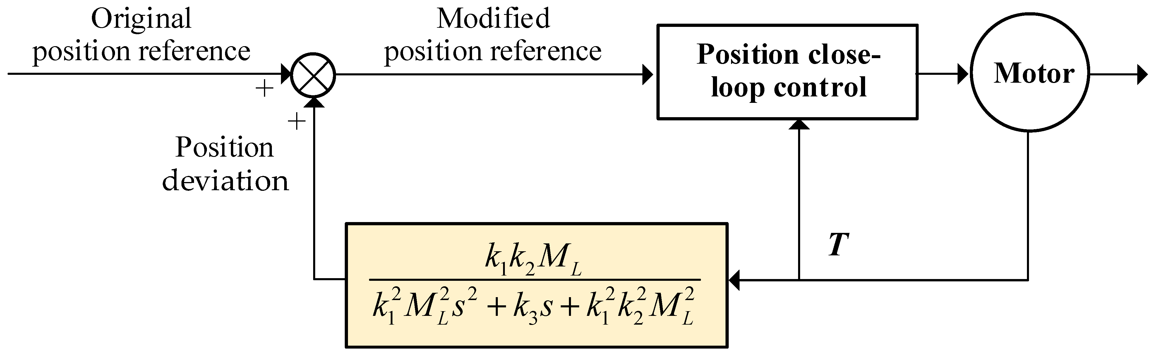
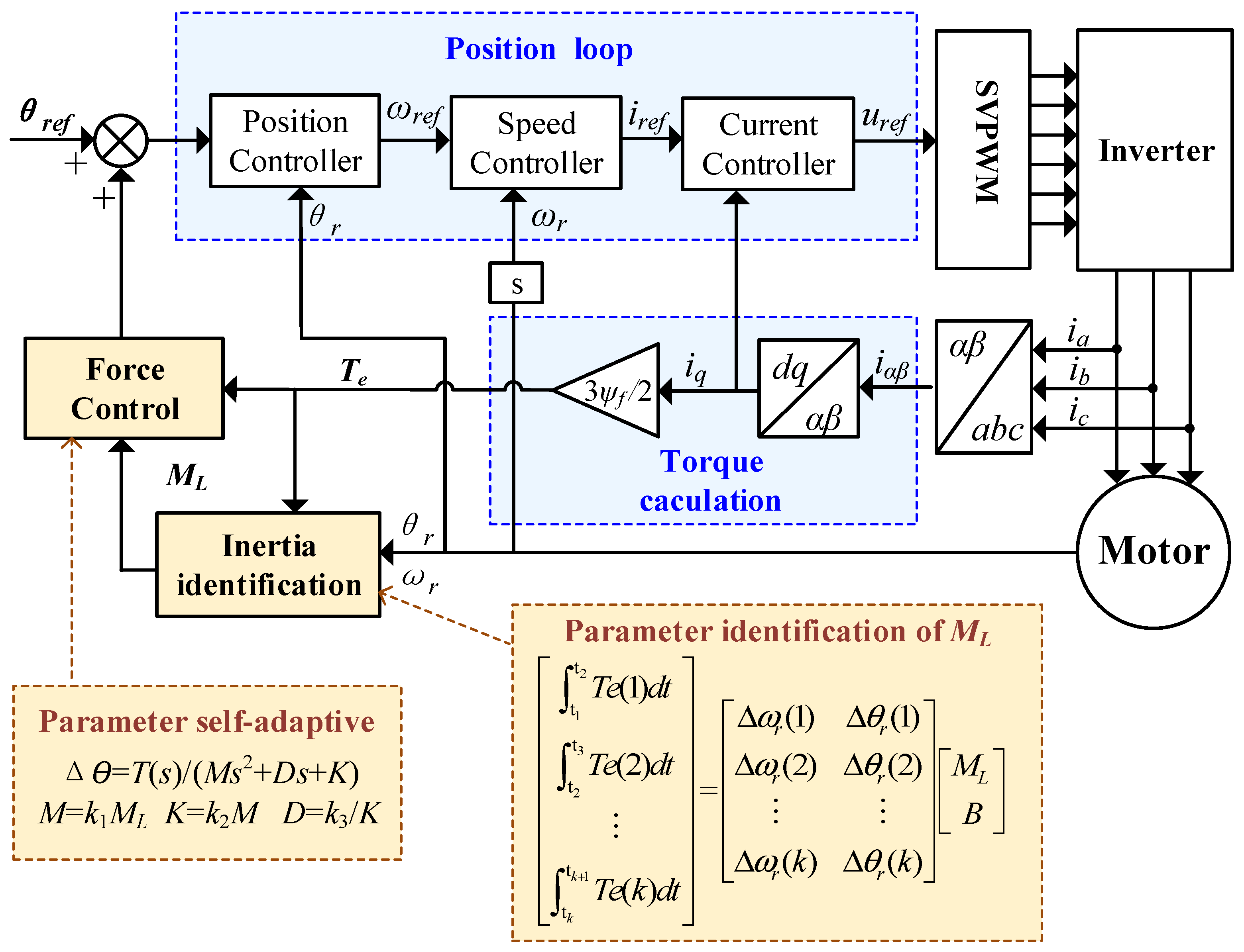
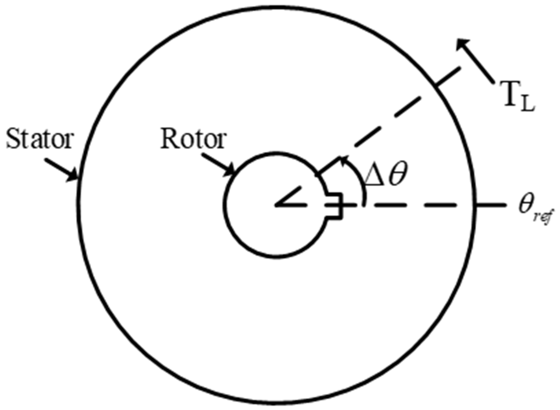
3.1. Control Algorithm
3.2. Control System
4. Experimental Validations
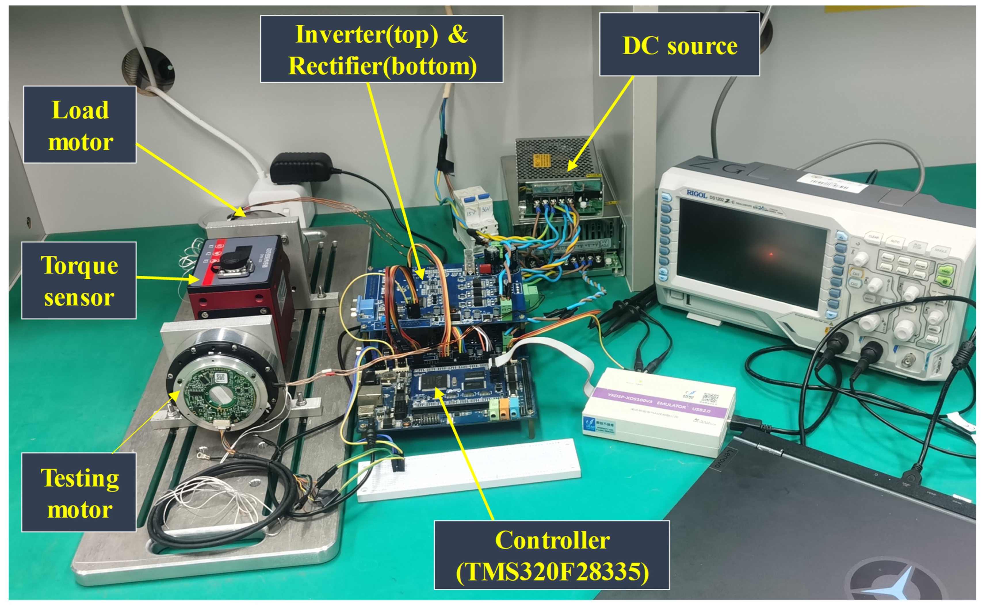
4.1. Experimental Instruments and Plarform
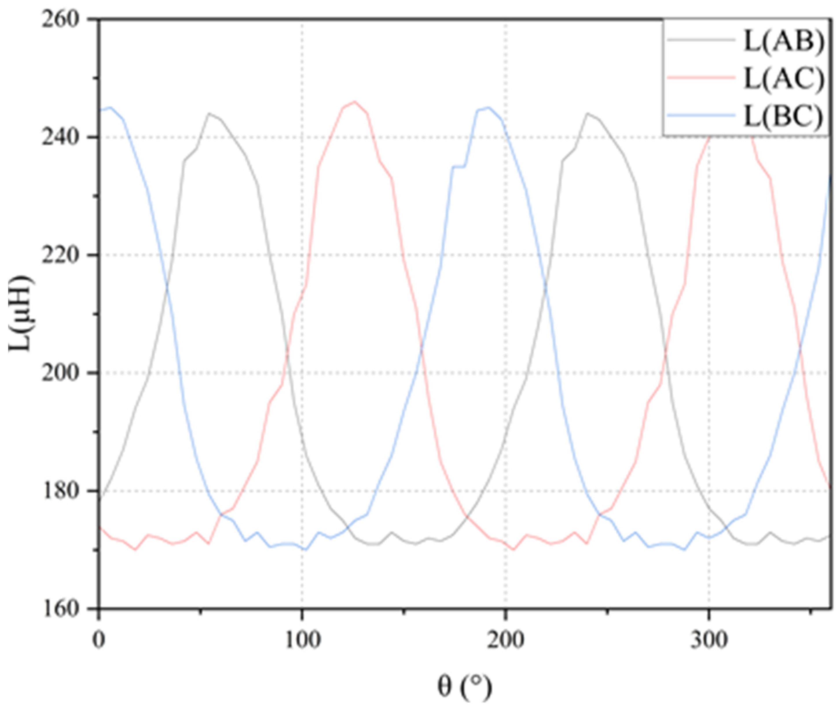
4.2. Experimental Validations of the FEA Results
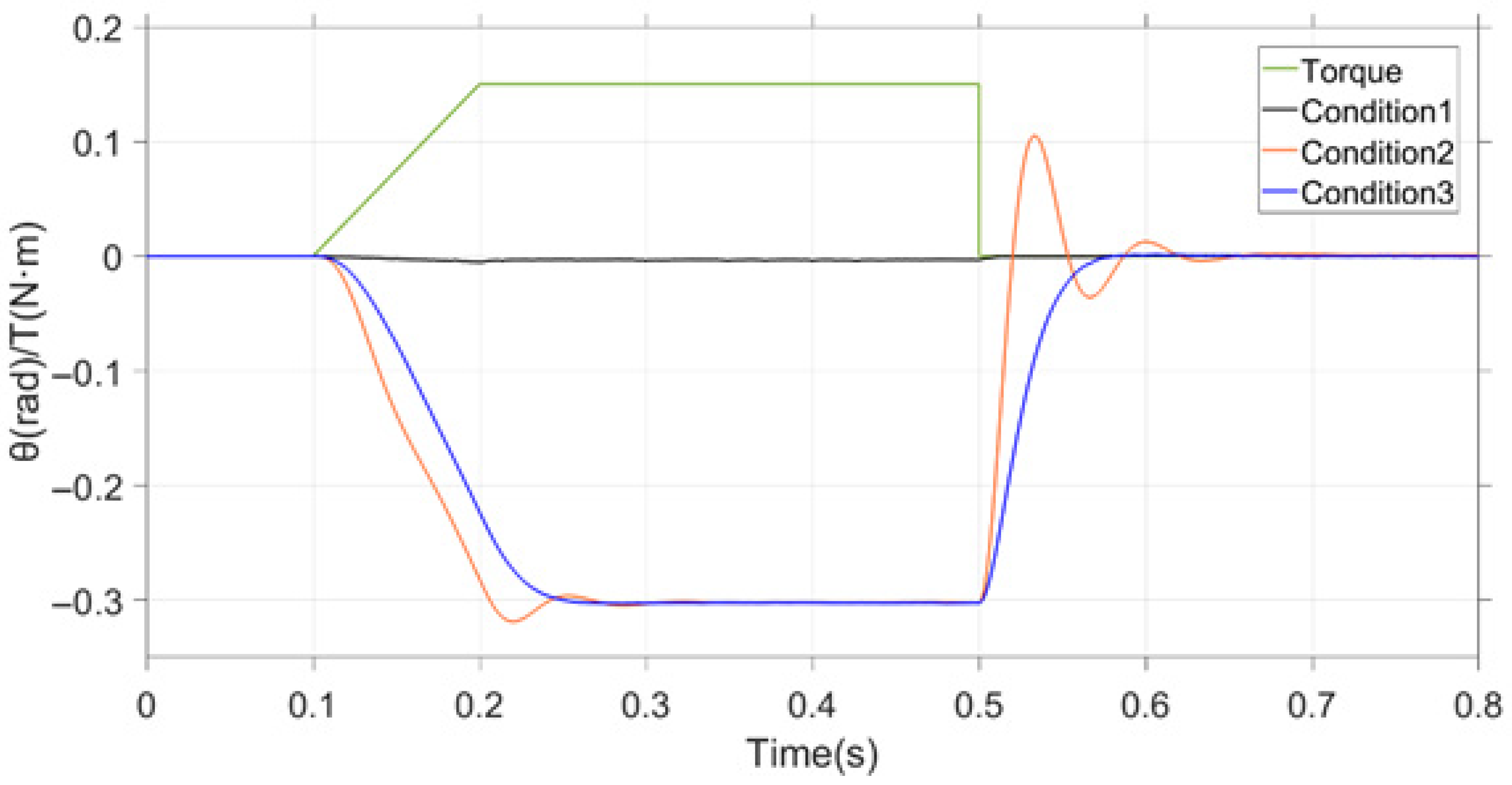
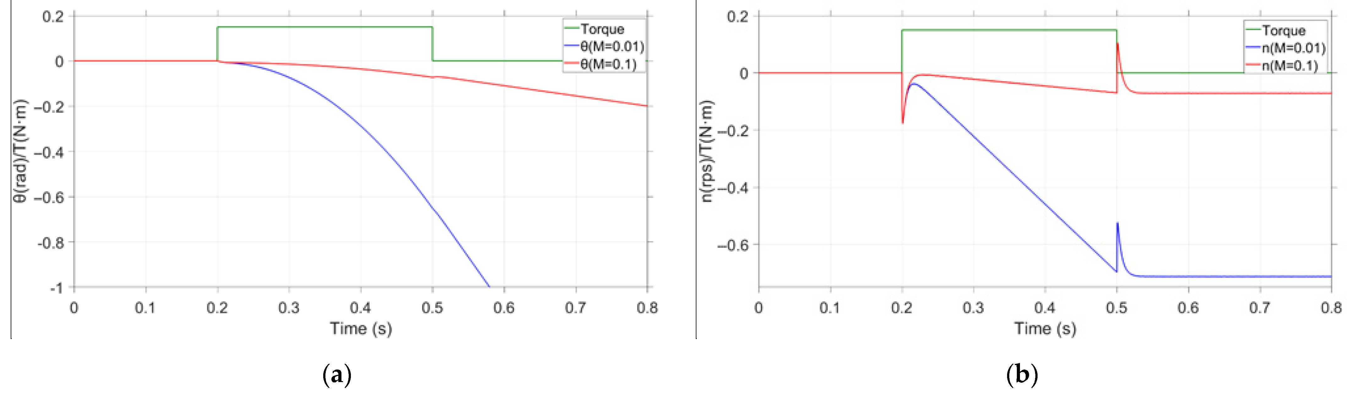
4.3. Experimental Validations of Force Control
4.4. User Experience Results of the Exoskeleton
5. Conclusions
Supplementary Materials
Author Contributions
Funding
Data Availability Statement
Conflicts of Interest
References
- Benjamin, G.K. A Low-Cost Modular Actuator for Dynamic Robots. Master’s Thesis, Massachusetts Institute of Technology, Cambridge, MA, USA, 2018. [Google Scholar]
- Alexander, H. Design of a High Torque Density Modular Actuator for Dynamic Robots. Master’s Thesis, Massachusetts Institute of Technology, Cambridge, MA, USA, 2020. [Google Scholar]
- Xue, J.; Chen, X.; Tian, Y.; Yu, Z.; Meng, F.; Huang, Q. A Dual-Motor Joint Model for Humanoid Robots. IEEE Trans. Robot. 2021, 37, 2621–2625. [Google Scholar]
- Khan, Z.; Naseer, F.; Khan, Y.; Bilal, M.; Butt, M. Study of Joint Symmetry in Gait Evolution for Quadrupedal Robots Using a Neural Network. Technologies 2022, 10, 64. [Google Scholar] [CrossRef]
- Li, W.; Wang, Y.; Togo, S.; Yokoi, H.; Jiang, Y. Development of a Humanoid Shoulder Based on 3-Motor 3 Degrees-of-Freedom Coupled Tendon-Driven Joint Module. IEEE Robot. Autom. Lett. 2021, 6, 1105–1111. [Google Scholar] [CrossRef]
- Li, W.; Chen, P.; Bai, D.; Zhu, X.; Togo, S.; Yokoi, H.; Jiang, Y. Modularization of 2-and 3-DoF Coupled Tendon-Driven Joints. IEEE Trans. Robot. 2021, 37, 905–917. [Google Scholar] [CrossRef]
- Cao, W.J.; Chen, C.J.; Wang, D.S.; Wu, X.Y.; Chen, L.X.; Xu, T.T.; Liu, J.S. A Lower Limb Exoskeleton with Rigid and Soft Structure for Loaded Walking Assistance. IEEE Robot. Autom. Lett. 2022, 7, 454–461. [Google Scholar] [CrossRef]
- Yan, T.; Cempini, M.; Oddo, C.M.; Vitiello, N. Review of assistive strategies in powered lower-limb orthoses and exoskeletons. Robot. Auton. Syst. 2015, 64, 120–136. [Google Scholar] [CrossRef]
- Wang, G.; Liang, X.; Jiang, J. The Present State and Developing Tendency of Robot Joint. J. Mech. Transm. 2004, 28, 1–5. [Google Scholar]
- Park, J.; Kim, J.H.; Kim, K.S.; Kim, S. Design and control of antagonistic robot joint with Twisted String Actuators. In Proceedings of the 2016 13th International Conference on Ubiquitous Robots and Ambient Intelligence (URAI), Xi’an, China, 19–22 August 2016; pp. 563–565. [Google Scholar]
- Lee, J.; Lee, J.; Phuong, T.L.; Tung, K.N. Design of the Joint Motor for an Articulated Robot Considering Joint Load Characteristics. Energies 2021, 14, 6690. [Google Scholar] [CrossRef]
- Yin, H.; Yu, Y.; Li, J. Optimization design of a motor embedded in a lightweight robotic joint. In Proceedings of the 2017 12th IEEE Conference on Industrial Electronics and Applications (ICIEA), Siem Reap, Cambodia, 18–20 June 2017; pp. 1630–1634. [Google Scholar]
- Guo, L.; Wang, Z.; Song, Y.; Shan, X.; Gan, D. Structural optimization of a new type of lever-assisted gear reducer based on a genetic algorithm. Mech. Sci. 2021, 12, 333–343. [Google Scholar] [CrossRef]
- Huang, J.; Li, C. The High-payload Manipulator Development Based on Novel Two-stage Cycloidal Speed Reducers and Hub Motors. In Proceedings of the 2020 5th International Conference on Precision Machinery and Manufacturing Technology, Auckland, New Zealand, 3–7 February 2020; Volume 1583. [Google Scholar]
- Liu, Y.; Zhu, Z. Influence of Gear Ratio on the Performance of Fractional Slot Concentrated Winding Permanent Magnet Machines. IEEE Trans. Ind. Electron. 2018, 66, 7593–7602. [Google Scholar] [CrossRef] [Green Version]
- Aitor, T.; Amaia, L.; Irma, V.; Fernando, B. Modeling of End-Space Convection Heat-Transfer for Internal and External Rotor PMSMs with Fractional-Slot Concentrated Windings. IEEE Trans. Ind. Electron. 2020, 68, 1928–1937. [Google Scholar]
- Liu, G.; Zhai, F.; Chen, Q. Torque Pulsation Reduction in Fractional-Slot Concentrated-Windings IPM Motors by Lowering Sub-Harmonics. IEEE Trans. Energy Convers. 2019, 34, 2084–2095. [Google Scholar] [CrossRef]
- Totoki, E.; Yamaguchi, S.; Tanaka, T.; Ito, K.; Daikoku, A.; Morimoto, S. Torque Ripple Reduction for Permanent Magnet Motor using New Configuration for Concentrated Windings. IEEJ J. Ind. Appl. 2022, 11, 531–537. [Google Scholar] [CrossRef]
- Vansompel, H.; Sergeant, P. Extended End-Winding Cooling Insert for High Power Density Electric Machines with Concentrated Windings. IEEE Trans. Energy Convers. 2020, 35, 948–955. [Google Scholar] [CrossRef]
- Wang, J.; Wan, Z.; Dong, Z.; Li, Z. Research on Performance Test System of Space Harmonic Reducer in High Vacuum and Low Temperature Environment. Machines 2021, 9, 1. [Google Scholar] [CrossRef]
- Zhang, N.; Zhang, Y.; Li, Y. Optimization Method for Double-Arc Tooth Profile of Harmonic Reducer. J. Xi’an Jiaotong Univ. 2019, 53, 31–37. [Google Scholar]
- Tao, M.; Chen, Y.; Chen, D.; Wu, J.; Chen, F.; Li, B.; Mei, J. Research Present Status and Outlook of Harmonic Reducer Testing Technology. J. Mech. Transm. 2018, 42, 175–180. [Google Scholar]
- Lin, W.; Shih, Y.; Lee, J. Design of a Two-Stage Cycloidal Gear Reducer with Tooth Modifications. Mech. Mach. Theory 2014, 79, 184–197. [Google Scholar] [CrossRef]
- Ma, S.; Shi, Y.; Gao, Y.; Guo, J. Gear Checking for the Sun Gear in Planet-Gear Reducer based on Practical Engineering Application. In Proceedings of the 2020 3rd World Conference on Mechanical Engineering and Intelligent Manufacturing (WCMEIM 2020), Shanghai, China, 4–6 December 2020; pp. 575–578. [Google Scholar]
- Li, Y.; Jiang, K.; Zeng, T.; Chen, W.; Li, X.; Li, D.; Zhang, Z. Belief reliability modeling and analysis for planetary reducer considering multi-source uncertainties and wear. J. Syst. Eng. Electron. 2021, 32, 1246–1262. [Google Scholar]
- Cao, L.; Xia, Y.; Shen, Y.; Wang, J.; Shan, T.; Lin, Z. Fault Characteristics Analysis of Planetary Gear of Helicopter Main Reducer. In Proceedings of the 2019 Prognostics and System Health Management Conference (PHM-QINGDAO), Qingdao, China, 25–27 October 2019. [Google Scholar]
- Kiguchi, K.; Hayashi, Y. An EMG-Based Control for an Upper-Limb Power-Assist Exoskeleton Robot. IEEE Trans. Syst. Man Cybern. Part B-Cybern. 2012, 42, 1064–1071. [Google Scholar] [CrossRef]
- Maples, J.; Becker, J. Experiments in force control of robotic manipulators. In Proceedings of the 1986 IEEE International Conference on Robotics and Automation, San Francisco, CA, USA, 7–10 April 1986; pp. 695–702. [Google Scholar]
- Jeong, D.; Jung, S. Comparison Studies of Two Major Force Control Algorithms for a Single Axis Force Control of a Robot Manipulator. In Proceedings of the 2021 21ST International Conference on Control, Automation and Systems (ICCAS 2021), Jeju, Republic of Korea, 12–15 October 2021; pp. 2243–2246. [Google Scholar]


| Motor Part | Parameter | Value |
|---|---|---|
| Stator core | Outer diameter | 76.4 mm |
| Inner diameter | 58.5 mm | |
| Slot Number | 36 | |
| Tooth width | 2 mm | |
| Yoke width | 1.5 mm | |
| Stack length | 7 mm | |
| Rotor core | Outer diameter | 84 mm |
| Inner diameter | 77.4 mm | |
| Pole number | 40 | |
| Pole-arc coefficient | 0.88 | |
| Core thickness | 1.5 mm | |
| Stack length | 10 mm | |
| Material | 20WTG1500 | |
| Permanentmagnet | Pole number | 40 |
| Material | N38SH | |
| Thickness | 1.8 mm | |
| Cross section area(single) | 9.96 mm2 | |
| Axial direction height | 7 mm | |
| Total weight | 21.2 g | |
| Windings | Turns | 13 |
| Series coils number (one phase) | 12 | |
| Diameter (with insulating layer) | 0.64 mm | |
| Linear density | 0.02372 g/cm | |
| Resistivity | 666 μΩ/cm@20 °C | |
| Single slot area | 26.7 mm2 | |
| Slot filling factor | 40% | |
| Single coil length | 21.8 mm | |
| Total winding weight | 27.4~28.7 g |
| Stack Length to Outer Diameter Ratio, kld | 0.16 | 0.17 | 0.18 | 0.19 | 0.20 | 0.21 | 0.22 | 0.23 | 0.24 | 0.25 |
| 3D End Effect Coefficient, kend | 0.880 | 0.912 | 0.935 | 0.946 | 0.955 | 0.96 | 0.965 | 0.969 | 0.973 | 0.976 |
| Gear | Teeth Number | Modulus | Reference Diameter |
|---|---|---|---|
| Gear ring | 108 | 0.5 mm | 54.0 mm |
| Planet gear | 48 | 0.5 mm | 24.0 mm |
| Sun gear | 12 | 0.5 mm | 6.0 mm |
| Parameter | 3D FEA Results | Experiment Results |
|---|---|---|
| AB phase series resistance | 480~500 mΩ | AB: 0.537 Ω |
| AC: 0.531 Ω | ||
| BC: 0.541 Ω | ||
| AB phase series inductor | 160~240 μH | 160~250 μH |
| Peak of line voltage@600 r/min | 7.27 V | 7.3 V |
| [email protected] Arms, 600 r/min | 0.2 Nm | 0.21 Nm |
| Maximum efficiency | >91% | >93% |
| Winding temperature (40 min) @RT 30 °C | <130 °C | ~90 °C |
| Case | Performances | Without Exoskeleton | Wearing Exoskeleton | Improvement |
|---|---|---|---|---|
| 1 | Top walking speed keeping heart rate under 90 bit/min | 4.1 km/h | 4.6 km/h | 12.2% |
| 2 | Top running speed keeping heart rate under 120 bit/min | 6.3 km/h | 7.9 km/h | 25.4% |
| 3 | Top running speed keeping heart rate under 165 bit/min | 8.4 km/h | 9.6 km/h | 14.3% |
| 4 | Lifting weight | 21.0 kg | 27.4 kg | 30.5% |
Disclaimer/Publisher’s Note: The statements, opinions and data contained in all publications are solely those of the individual author(s) and contributor(s) and not of MDPI and/or the editor(s). MDPI and/or the editor(s) disclaim responsibility for any injury to people or property resulting from any ideas, methods, instructions or products referred to in the content. |
© 2023 by the authors. Licensee MDPI, Basel, Switzerland. This article is an open access article distributed under the terms and conditions of the Creative Commons Attribution (CC BY) license (https://creativecommons.org/licenses/by/4.0/).
Share and Cite
Zhang, G.; Tong, Q.; Zhang, T.; Tao, J.; Qiu, A. Design of a High Torque Density Robot Joint and Analysis of Force Control Method Applied for a Light Exoskeleton. Electronics 2023, 12, 397. https://doi.org/10.3390/electronics12020397
Zhang G, Tong Q, Zhang T, Tao J, Qiu A. Design of a High Torque Density Robot Joint and Analysis of Force Control Method Applied for a Light Exoskeleton. Electronics. 2023; 12(2):397. https://doi.org/10.3390/electronics12020397
Chicago/Turabian StyleZhang, Gan, Qing Tong, Taixun Zhang, Jinxin Tao, and Anjian Qiu. 2023. "Design of a High Torque Density Robot Joint and Analysis of Force Control Method Applied for a Light Exoskeleton" Electronics 12, no. 2: 397. https://doi.org/10.3390/electronics12020397