Article

Phase Diffusion in Low-EJ Josephson Junctions at Milli-Kelvin Temperatures

Department of Physics and Astronomy, Rutgers University, Piscataway, NJ 08854, USA
*
Author to whom correspondence should be addressed.
Electronics 2023, 12(2), 416; https://doi.org/10.3390/electronics12020416
Submission received: 7 December 2022 / Revised: 9 January 2023 / Accepted: 10 January 2023 / Published: 13 January 2023
(This article belongs to the Special Issue Nanofabrication of Superconducting Circuits)

Abstract

:
Josephson junctions (JJs) with Josephson energy E J 1 K are widely employed as non-linear elements in superconducting circuits for quantum computing operating at milli-Kelvin temperatures. In the qubits with small charging energy E C ( E J / E C 1 ), such as the transmon, the incoherent phase slips (IPS) might become the dominant source of dissipation with decreasing E J . In this work, a systematic study of the IPS in low- E J JJs at milli-Kelvin temperatures is reported. Strong suppression of the critical (switching) current and a very rapid growth of the zero-bias resistance due to the IPS are observed with decreasing E J below 1 K. With further improvement of coherence of superconducting qubits, the observed IPS-induced dissipation might limit the performance of qubits based on low- E J junctions. These results point the way to future improvements of such qubits.

1. Introduction

Josephson junctions (JJs) with the Josephson energy 0.1 K < E J < 1 K have been recently employed as non-linear elements of superconducting qubits (see, e.g., [1,2,3,4]). Though E J of these junctions remains much greater than the physical temperature of qubits (∼20 ÷ 50 mK), a non-zero rate of thermally-activated phase slips in these junctions might soon limit the coherence of superconducting qubits. Indeed, with the qubit coherence time exceeding 1 ms [5], even rare dissipative events might become significant. Thus, the study of incoherent phase slips, induced by either equilibrium (thermal) or non-equilibrium noise, might help better understand the limitations of the low- E J JJs as elements of quantum circuits operating at mK temperatures.
In the past, phase slips in JJs [6] and associated phase diffusion [7,8,9,10] attracted a great deal of experimental and theoretical attention. This effort was mainly aimed at better understanding of a crossover from the classical Josephson behavior (well-defined phase difference, strong quantum fluctuations of charge) to the Coulomb-blockade regime (localized charges, strong quantum fluctuations of phase) (see, e.g., [11,12,13,14] and references therein). The crossover is observed in ultra-small JJs with the Josephson energy E J of the same order of magnitude as the Coulomb energy E C = ( 2 e ) 2 / ( 2 C J ) ( C J is the effective JJ capacitance) provided the junctions are included in a circuit with the impedance Z greatly exceeding the quantum resistance R Q = h / ( 2 e ) 2 6.5   k Ω . The rate of the coherent phase slip processes (the so-called quantum phase slips, or QPS) exponentially increases with decreasing the ratio E J / E C [15].
The qubit dephasing by QPS [16] has been considered for the charge-sensitive transmon qubits [17] and heavy fluxonium qubits [1,18,19]. However, energy relaxation due to the incoherent phase slips in the ubiquitous elements of the multi-qubit circuits, the charge-insensitive transmons, has never been addressed. To fill this gap, in the current paper the dissipative processes in the low- E J Josephson junctions are systematically studied in the regime E J T E C , which is relevant for operation of superconducting qubits shunted with a large external capacitance [13,14,15]. In this regime, quantum fluctuations of charge are strongly enhanced and the QPS are suppressed. To explore the dynamics of low- E J junctions at mK temperatures, we designed JJs with E J = 0.1–1 K and E C < 10 mK, and studied the IPS in these JJs with low-frequency transport measurements. The JJs in this work have been implemented as SQUIDs to allow in-situ tuning of E J by the magnetic field.
The paper is organized as follows. In Section 2, the known facts about the phase diffusion induced by incoherent phase slips in underdamped JJs are briefly reviewed. The sample design and experimental techniques are discussed in Section 3. The measurements of current-voltage characteristics (IVC) of low- E J devices are presented in Section 4. In Section 5, our results and the data reported by other groups are discussed with the focus on implications of the dissipation induced by incoherent phase slips for the operation of qubits that employ low- E J Josephson junctions. The conclusions are presented in Section 6.

2. Phase Diffusion in Underdamped Junctions

At T = 0 , the critical current I C A B of a “classical” JJ ( E J E C ) is provided by the Ambegaokar–Baratoff relation [6]
I C A B ( T = 0 ) = 2 e E J = π Δ ( 0 ) 2 e R N ,
where Δ is the superconducting energy gap and R N is the normal-state resistance of a JJ. This relation has been derived by neglecting phase fluctuations. In the absence of non-equilibrium noise and charging effects, the voltage drop across a JJ is expected to be zero at I < I C A B ( T = 0 ) . The quantum phase fluctuations, which become strong at E J E C , result in the so-called coherent quantum phase slips (CPS) in one-dimensional JJ chains (see [20,21,22] and references therein). The junction capacitance C plays the role of the effective mass of a fictitious particle that tunnels between the minima of the “washboard” potential U ( φ ) = E J cos φ I 2 e φ [6]. Reduction of C and, thus, increase of E C , facilitates tunneling and promotes CPS. The CPS shift the system energy levels and renormalize the effective Josephson coupling E J * E J 2 / E C . The CPS also result in energy dissipation in one-dimensional superconducting wires [23,24] as well as in the external circuits connected to the Josephson junctions.
In the regime E J E C , on the other hand, the incoherent classical phase slips (IPS) induced by either non-zero temperature or non-equilibrium noise are expected to dominate. The IPS correspond to the over-the-barrier activation in the washboard potential [6]. In thermal equilibrium, the IPS rate depends exponentially on the temperature: ν I P S ω p e Δ U / k B T [6]. Here, ω p = 1 2 E J E C is the plasma frequency which plays the role of the attempt rate, Δ U is the height of the potential barrier, which is close to 2 E J at currents I I C A B .
The IPS process is analogous to a single flux quantum Φ 0 crossing a JJ (the process is dual to the transfer of a single Cooper pair through the JJ [25]). Each phase slip generates a voltage drop V ( t ) across the JJ, such that V ( t ) d t = Φ 0 and, in the presence of a current I, releases an energy I Φ 0 . Thus, the zero-voltage state can be destroyed by the energy dissipation due to the time-dependent phase fluctuations. At zero tilt of the “washboard” potential U ( φ ) , the phase slips with different signs of the phase change occur with the same probability and, as a result, the average voltage across the junction is zero. However, when the junction is biased with a non-zero current I, the tilt of the washboard potential breaks the symmetry and a non-zero average voltage proportional to the phase slip rate is generated across the junction.
The dynamics of JJs depends on all sources of dissipation, such as IPS, thermally excited quasiparticles, etc. The low-dissipative (underdamped) regime, observed at T Δ and in a high-impedance environment, is relevant to the operation of superconducting qubits. Typically, dissipation is highly frequency-dependent: it is strongly suppressed at low frequencies ω ω p and, potentially, significantly enhanced at frequencies approaching ω p . This frequency-dependent dissipation leads to the phenomenon of underdamped phase diffusion [7,8,26]. Characteristic signatures of this regime are the absence of the zero-voltage superconducting state and the existence of a low-voltage ( V 2 Δ e ) IVC branch, which extends up to I S W I C A B . The IVC is hysteric at currents I < I S W : the low-V branch observed with increasing the current from 0 to I S W coexists with a high-voltage ( V 2 Δ e ) branch observed with decreasing the current from I > I S W to zero. At high voltages V > 2 Δ e , the main dissipation mechanism is the Cooper pair breaking and generation of non-equilibrium quasiparticles. In the low-voltage state V < 2 Δ e , the energy gained by a system in the process of the over-the-barrier activation is dissipated mostly due to the Josephson radiation [27].
The theory of the DC transport in underdamped Josephson junctions in the regime E C T E J < Δ in presence of a stochastic noise has been developed by Ivanchenko and Zilberman [28] (the IZ theory, see Appendix C). The IZ theory predicts that I S W E J 2 at small E J [29], in contrast to the dependence I C A B E J for the regime E C , T E J (Equation (1)).
More recent analysis of the effect of non-zero temperature in the underdamped junctions was provided by Kivioja et al. [30]. By considering the quality factor at the plasma frequency, Q ( ω p ) , and the energy dissipated between adjacent potential maxima Δ E D 8 E J / Q ( ω p ) , Kivioja et al. showed that the maximum possible power dissipated due to phase diffusion before switching to a state with V 2 Δ / e can be expressed as
2 π V Φ 0 × Δ E D 2 π = V × I S W ,
where I S W = 4 I C / π Q is the maximum possible current carried by underdamped junctions in the phase diffusion (UPD) regime. At I < I S W , there is a non-zero probability for a fictitious particle to be retrapped after escape from a local minimum of the potential U ( φ ) . As a result, instead of a run-away state with V = 2 Δ / e , the IVC demonstrates a non-zero slope at I < I S W due to the phase diffusion. The value of R 0 , therefore, provides valuable information regarding the nature of damping in the junction circuits.

3. Experimental Techniques

All the samples studied in this work have been implemented as SQUIDs, in order to be able to in-situ tune E J by changing the magnetic flux Φ in the SQUID loop [6]:
E J = 2 E J 0 cos ( π Φ Φ 0 ) ,
Figure 1 schematically shows the design of a chain of SQUIDs formed by small ( 0.2 × 0.2 μ m 2 ) JJs. The area of the SQUID loop, A S Q U I D , varied between 6 μ m 2 and 50 μ m 2 . The chains of SQUIDs had additional contact pads (shown in yellow in Figure 1) to provide access to individual SQUIDs or pairs of SQUIDs within a chain.
In order to reduce the rate of quantum phase slips ν Q P S exp ( 2 E J E C ) [6], either the low-transparency JJs junctions with a relatively large in-plane area A J J ( > 1 μ m 2 ), or smaller junctions shunted with external capacitors (the design details are provided in Appendix A) have been used. In both cases, the charging energy E C was reduced below 10 mK, and this allowed us to maintain a large ratio E J / E C for all studied JJs.
The amplitude of variations of E J with the external magnetic field depends on scattering of parameters of individual JJs that form a nominally symmetric SQUID. This scattering did not exceed 10 % for the JJs with the normal-state resistance R N 1 k Ω and A J J = 0.02 μ m 2 . However, fabrication of the low-transparency JJs with R N 100 k Ω and A J J = 4 μ m 2 (the nominal critical current density I C A B / A J J 5 × 10 4 A / cm 2 ), which required very long oxidation times and high partial pressure of O 2 , resulted in a larger ( 30 % ) scattering of the R N values (Appendix A). This scattering was one of the reasons for different dependence I S W ( B ) observed for the nominally identical SQUID chains (see below). The parameters of representative samples are listed in Table 1 (the total number of tested samples exceeded 50 [31]).

4. Current-Voltage Characteristics of Low- E J Junctions

The results below focus on data obtained at T < 200 mK—in this temperature range one can neglect transport of the thermally-excited quasiparticles in A l -based superconducting circuits. Typical IVC measured at T b a s e = 25 mK for the samples with E J 1 K and E J 1 K are shown in Figure 2. Several characteristic features of the IVC are addressed below.

4.1. The Switching Current I S W and the Zero-Bias Resistance R 0

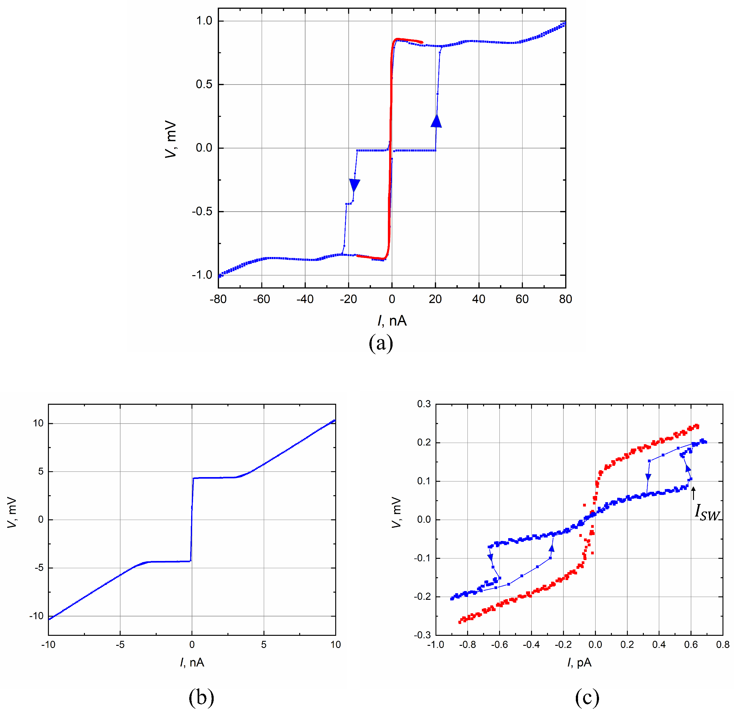
Figure 2 shows how the switching current I S W and the zero-bias resistance R 0 measured at small DC voltages V 2 Δ / e and currents I I S W are determined. Note that the zero-bias resistance per junction is twice as large as the zero-bias resistance of a SQUID. For the JJs with E J = 0.76 K (Figure 2a) a non-zero R 0 could not be detected within the accuracy of measurements conducted in this work ( 10 2 10 3 Ω , depending on the magnitude of I S W ). This is the behavior expected in the “classical” regime E J T , E C . At currents I > I S W , the voltage across the chain approaches the value N × 2 Δ / e , where N is the number of SQUIDs in the chain and 2 Δ e × 0.4 mV is the sum of superconducting energy gaps in the electrodes that form a junction. For the chains with E J 1 K, the switching current is several orders of magnitude smaller than the Ambegaokar–Baratoff critical current (Figure 2c). With the magnetic field B approaching the value Φ 0 / ( 2 A S Q U I D ) , the switching current vanishes and R 0 increases by orders of magnitude (red curves in Figure 2a,c). The IVC at Φ = Φ 0 / 2 resemble that observed in the Coulomb-blockade regime. Note that for most of the studied samples in this regime E C is close to the base temperature, so the Coulomb blockade is partially suppressed by thermal effects. The resistance R 0 ( Φ = Φ 0 / 2 ) for the samples with E J 1 K is limited by the input resistance of the preamplifier (a few G Ω ).
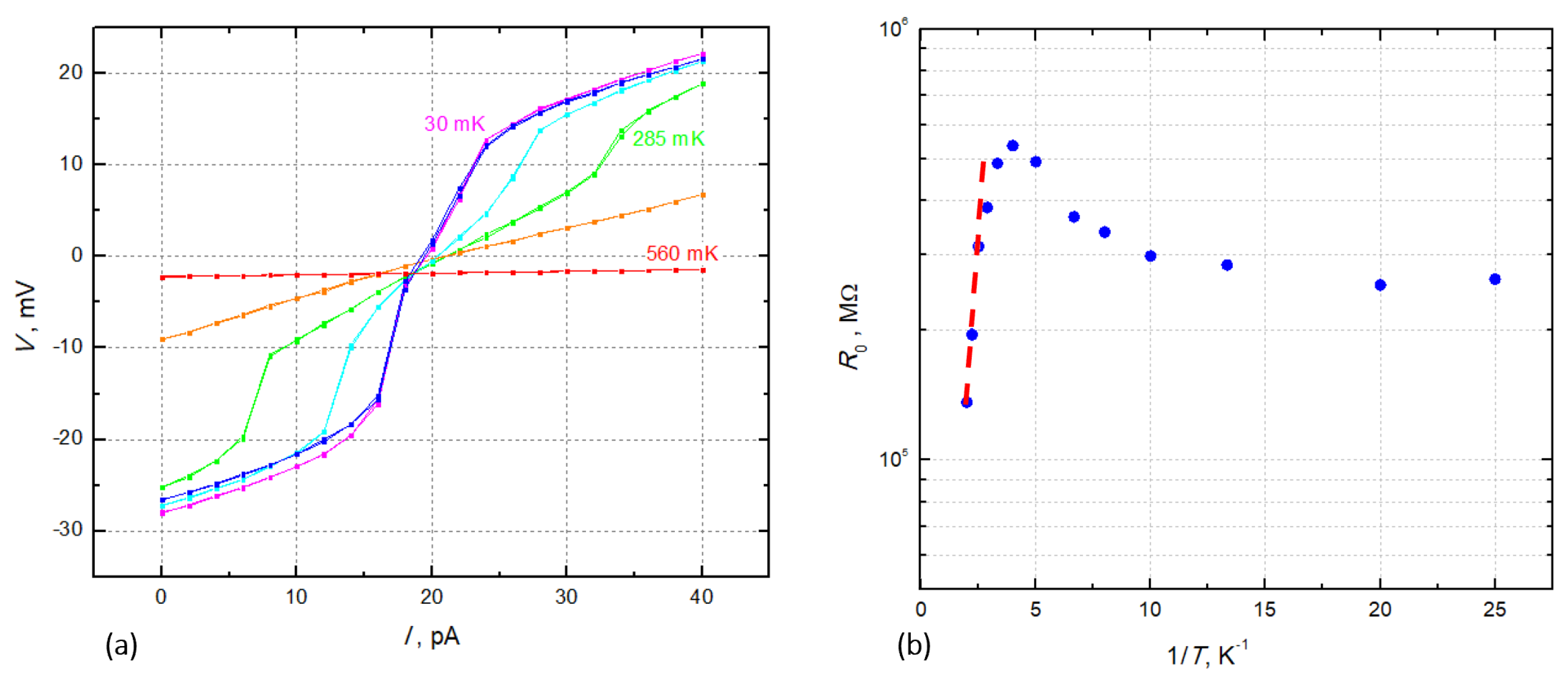
The evolution of the IVC measured at different temperatures for Φ = Φ 0 / 2 is shown in Figure 3a. The R 0 ( T ) drop observed with an increase of temperature at T > 0.2 K (Figure 3b) is due to an increasing concentration of thermally excited quasiparticles in A l electrodes: the JJ becomes “shunted” by the quasiparticle current. The dependence R 0 ( T ) at T > 0.25 K can be approximated by the Arrhenius dependence R 0 ( Φ = Φ 0 / 2 , T ) e x p ( δ / k B T ) with δ 2.1 K. The activation energy δ is close to the superconducting energy gap Δ 2.3 K in Al electrodes with T C 1.3 K.

4.2. The IVC Hysteresis

For all studied samples, strong hysteresis of the IVC is observed at Φ = n Φ 0 where n is integer. The hysteresis is a signature of the underdamped junctions with the McCumber parameter β 1 [32]. Observation of the hysteresis is also an indication that the noise currents I N in the measuring setup are significantly smaller than the switching current even for the samples with I S W in the sub-pico-A range (in the opposite limit, I N > I S W , the hysteresis vanishes, see Appendix C and Ref. [33]).

4.3. The I S W ( B ) Dependences

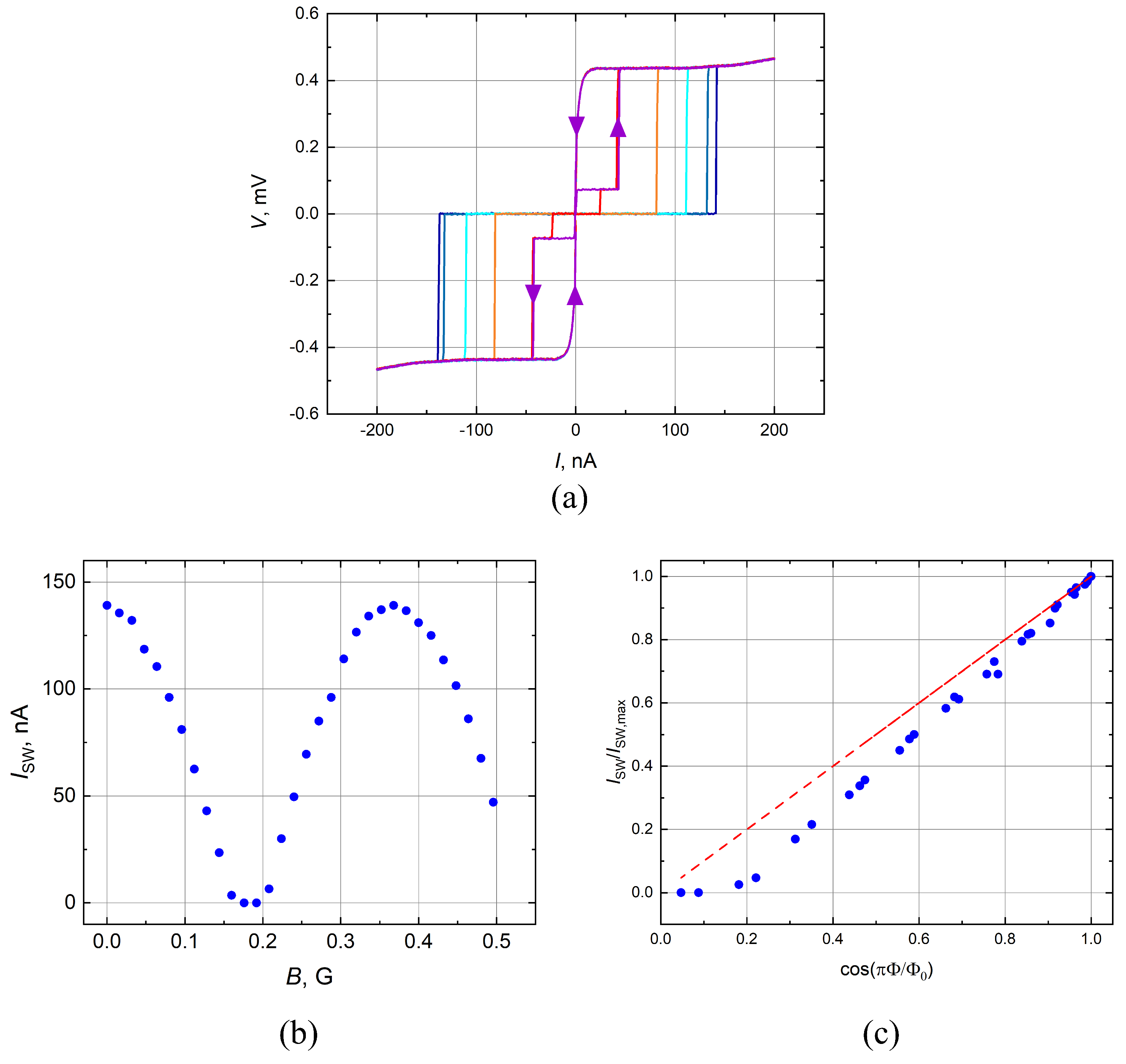
Even in the “classical” regime E J E C , T , several unexpected results are obtained. Firstly, the dependence of I S W ( Φ ) for some samples significantly deviated from the dependence
I S W ( Φ ) = I S W ( Φ = 0 ) × cos ( π Φ Φ 0 ) ,
(see Figure 4c). These deviations can be at least partially explained by a relatively large scattering of parameters of individual JJs and non-uniformity of the local magnetic field in the SQUID loops due to the magnetic field focusing. Observation of a steeper drop of I S W with Φ 0.5 Φ 0 than that predicted by Equation (3) can be attributed to violation of the condition E J ( Φ ) E C and crossover to the Coulomb blockade regime.
Secondly, sub-gap ( V s u b g a p < 2 Δ / e ) voltage steps on the IVC are observed (Figure 4a), which significantly reduced the accuracy of extraction of I S W and R 0 at the values of Φ close to Φ 0 / 2 . A possible reason for appearance of sub-gap steps might be the Fiske resonances due to the microwave resonant modes of the circuit [34]. Identifying the circuit elements that would be responsible for the corresponding resonance frequencies at f r e s = ( 75 μ eV ) / h 18 GHz (this frequency corresponds to a wavelength ∼2.5 mm for the electromagnetic wave propagating along the interface between a silicon substrate and vacuum) requires further investigation.

5. Discussion

There are several potential sources of dissipation in Josephson circuits at T Δ , such as non-equilibrium quasiparticles or two-level systems in the circuit environment (see, e.g., [35] and references therein). However, we are unaware of a mechanism other than the IPS that would explain the observed strong dependence of dissipation on the ratio E J / T . Below, we focus on the IPS as the dominant dissipation mechanism in this work.

5.1. The Switching Currents I S W

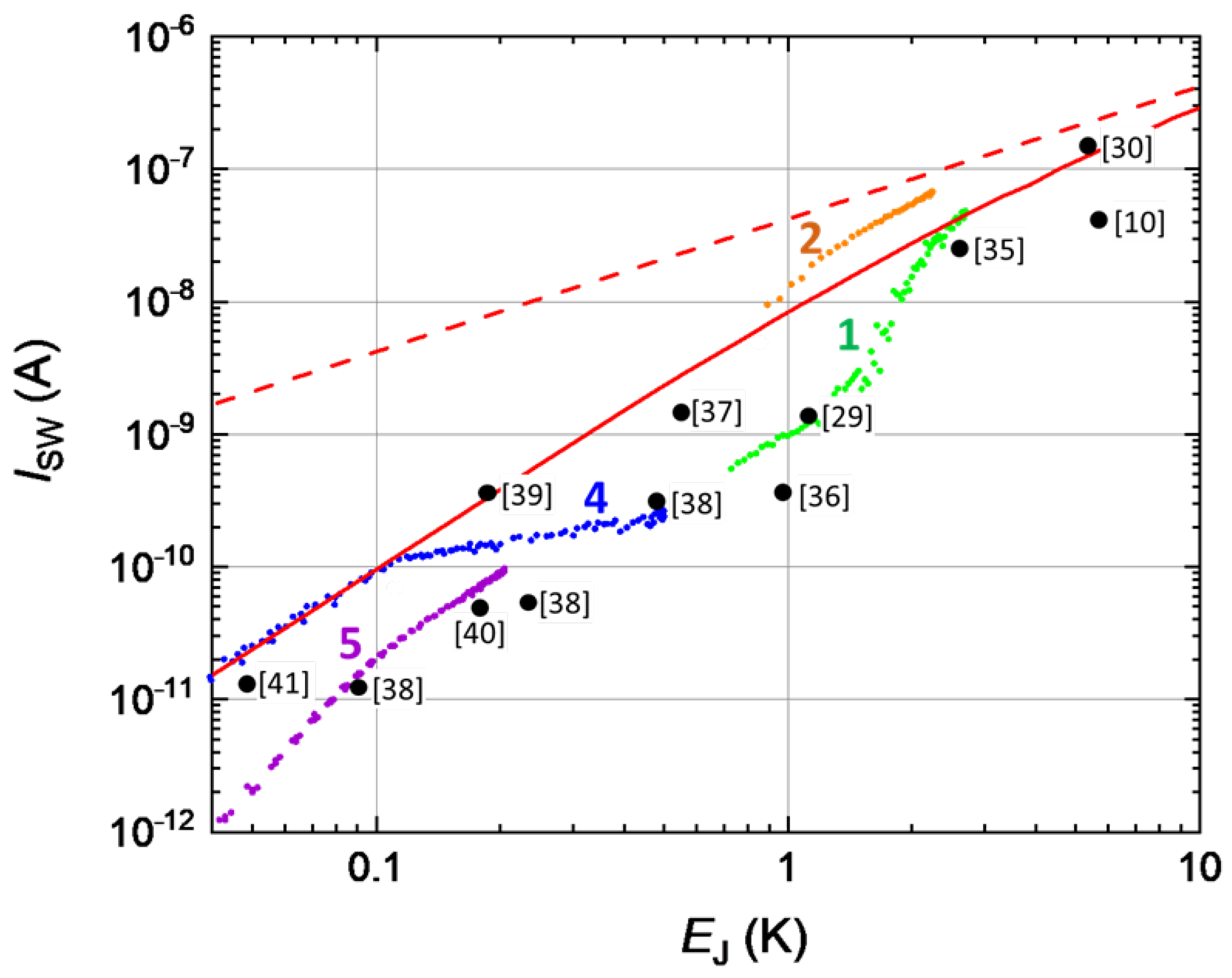
The results of I S W measurements for samples with different E J are summarized in Figure 5. Here, the data for four samples are plotted at different values of external magnetic flux threading the SQUIDs loop. The effective E J for these devices was calculated using Equation (2). For comparison, in Figure 5 the I S W data reported in literature for the JJs with large values of E J / E C are also plotted. Scattering of I S W values at a given E J can be attributed, at least partially, to different noise levels in different experimental setups, and to a relatively wide range of E J / E C values (see Table 2)—proliferation of QPS with decreasing E J / E C can strongly reduce I S W . Despite the data scattering, the general trend is clear: with decreasing E J , the switching current decreases significantly faster than the linear dependence I S W ( E J ) predicted by the Ambegaokar–Baratoff relationship (Equation (1)). At E J = 0.1 K, I S W is already two orders of magnitude smaller than I C A B ( T = 0 ) .
Qualitatively, the data are in agreement with theory of the DC transport in underdamped Josephson junctions with E C E J developed by Ivanchenko and Zilberman [28]. In the regime E C T E J < Δ , dissipation in the JJ circuits is associated with IPS induced by either an equilibrium noise generated by thermal excitation or a non-equilibrium noise. According to the IZ theory, the equation for the phase φ across a classical Josephson junction ( E C E J ) can be written as
2 e ( I b + I n ) = 1 R φ t + 2 e I C s i n φ ,
where I b is the bias current, I n ( 0 ) I n ( τ ) 2 k B T R δ ( τ ) is the delta-correlated Johnson–Nyquist noise across the resistance R connected in parallel with the junction. The superconducting part of the current as a function of bias voltage V B can be found by solving the corresponding Fokker–Planck equation (see Appendix D). With decreasing E J , the theory predicts a quadratic drop of the maximum superconducting current that the junction can sustain (i.e., the switching current I S W ) [29]. This maximum value of the switching current is realized at a non-zero voltage V n , which depends only on the voltage noise amplitude, so the zero-bias resistance in the IPS regime is expected to scale as E J 2 .
The dependence I S W ( E J ) predicted by the IZ theory in presence of additional Gaussian noise with amplitude of V n o i s e = 24 μ V is plotted in Figure 5. This noise corresponds to the Johnson–Nyquist noise δ V t = 4 k B T R Δ f generated at T = 50 mK by two 100 k Ω resistors connected in series with the device (Figure A2 in Appendix B). These chip resistors, designed for microwave applications, had a very small imaginary part of their impedance. The bandwidth was estimated as Δ f ω p / 2 π , where ω p / 2 π 1 GHz is the plasma frequency of the shunted JJs. Though the theory (the solid curve in Figure 5) is in qualitative agreement with the experimental data, most of the experimental I S W values are an order-of-magnitude smaller than I S W predicted by the IZ theory. A possible explanation for this discrepancy might be more complex phase dynamics in the devices with a very high IPS rate, outside of the limits of applicability of the IZ theory. Another possibility is the exponentially strong sensitivity of the IPS rate to the noise level in different setups and the physical temperature of samples, the parameters that are not easy to control in most experiments.

5.2. The Zero-Bias Resistance R 0

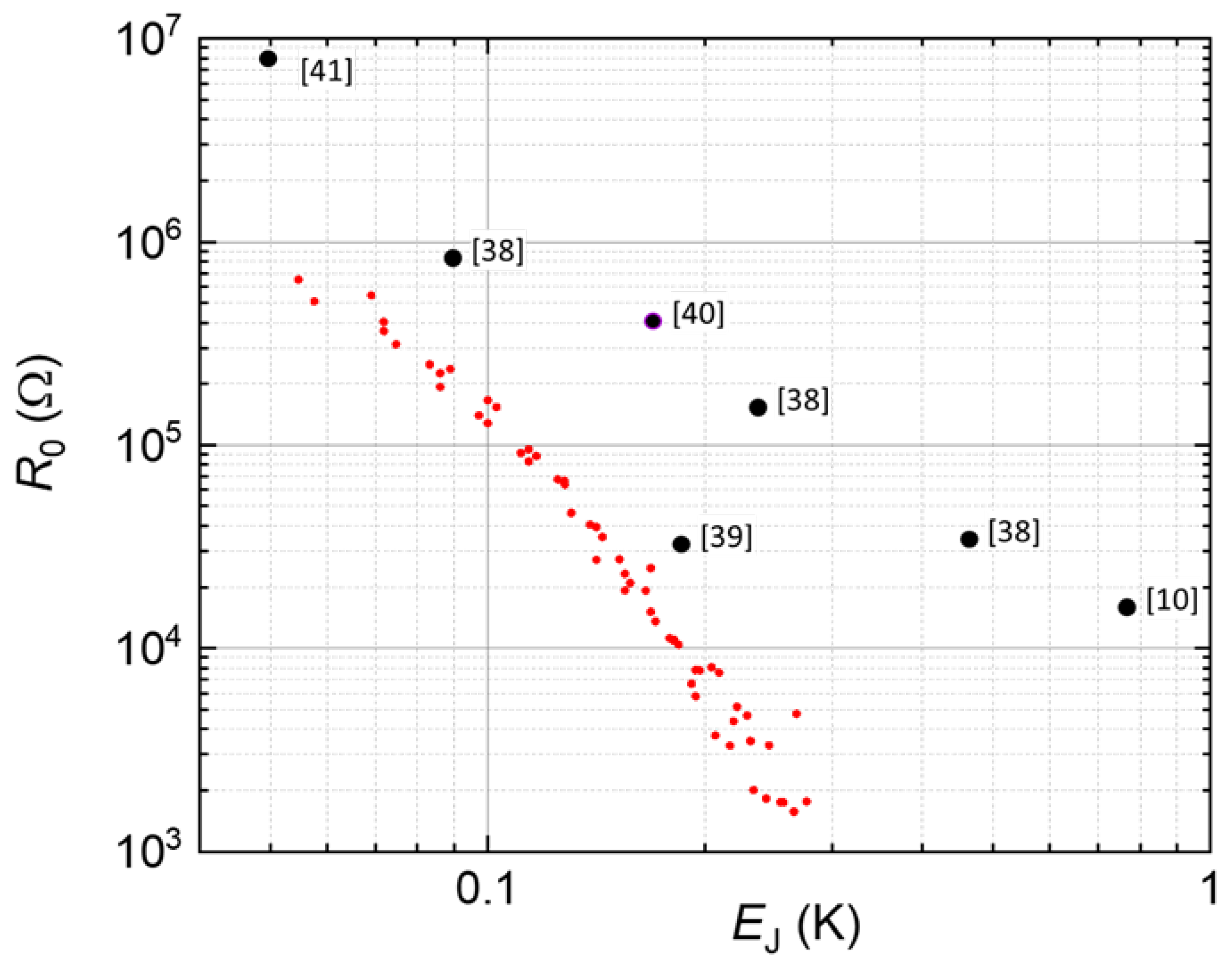
Figure 6 shows R 0 as a function of E J measured in this work and by other groups for A l / A l O X / A l junctions. To simplify the Figure, the data in this work are plotted only for the sample with the lowest values of R 0 (sample 5); R 0 for other samples are approximately in line with the data from literature shown in Figure 6. The zero-bias resistance, being unmeasurably low at E J > 1 K, rapidly increases at E J < 1 K, and becomes much greater than the normal-state resistance R N at E J 0.1 K. Instead of a well-defined “superconductor-to-insulator” transition at a certain value of E J / E C , a broad crossover between these two limiting regimes is observed. Note that different JJ samples (single junctions and arrays) demonstrate similar values of R 0 , though their charging energies could vary over a wide range.
Figure 5 and Figure 6 show that the findings are in good agreement with the literature data on the highest values of I S W and lowest values of R 0 measured for low- E J junctions. Despite large scattering of the data in Figure 5 and Figure 6, a very rapid drop of I S W and increase of R 0 has been observed in most of the experiments as soon as E J becomes significantly less than 1 K. Figure 5 shows that for typical experimental conditions, the crossover between the “classical” behavior I C E J to the behavior controlled by the phase diffusion occurs at E J 1 K. Note that the literature data in Figure 5 and Figure 6 correspond to samples with different values of the ratio E J / E C . Given strong scattering of I S W and R 0 , the effect of QPS is hard to detect. For the same reason, it is unclear if the impedance of the environment plays any significant role in these experiments; similar values of I S W could be observed for single JJ in a highly-resistive environment ( > 100 k Ω as in [36] and the setup in this work), single JJ in a low-impedance environment [37], and chains of SQUIDs frustrated by the magnetic field [31,35].
The observations are in line with an expected strong dependence of the IPS rate on the sample parameters in the regime E C T E J Δ . At E J T , one can estimate the rate of the thermally-generated IPS as Γ = ω p e x p ( 2 E J / k B T ) , where ω p is the plasma frequency (or an attempt rate) and e x p ( 2 E J / k B T ) is the probability of the over-the-barrier excitation. For example, at E J = 0.25 K and ω p / 2 π = 1.32 GHz, the rate decreases from 3 × 10 5 s 1 to 0.1 s 1 if the physical temperature decreases from 50 mK to 20 mK. This might also explain why the experimental results are so sensitive to the noise level in the experimental setup.
Table 2. The literature data on I S W and R 0 , ranked by E J .
Reference E J (K) E J / E C I C AB (nA) I SW (nA) R 0 (k Ω )
Watanabe 2003 [10] sample C5.78240400.6
Kivioja 2005 [30]5.2500220145
Schmidlin 2013 [33], Figure 5.22.550106250.13
Shimada 2016 [29],
SQUID at Φ / Φ 0 = 0.375
1.114471.20.11
Weissl 2015 [36],
SQUID at Φ / Φ 0 = 0.26
0.9510380.350.14
Watanabe 2003 [10] sample G0.76132 14
Jäck 2015 [38] Figure 4.60.54 1.513
Senkpiel 2020 [37]0.47 0.333
Senkpiel 2020 [37]0.23 0.07143
Yeh 2012 [39]0.181.36.50.3531
Jäck 2017 [40]0.17 7..50.05400
Murani 2020 [14]0.12 50.07
Senkpiel 2020 [37]0.09 0.012830
Kuzmin 1991 [41]0.05 1 0.0148000

6. Conclusions and Outlook

Phase slips in JJs have been actively studied over the last three decades in different types of Josephson circuits (single JJs, JJ arrays, etc.) over wide ranges of E J and E C . In this work, we focus on the incoherent phase slips, which are expected to become the dominant source of dissipation at sufficiently low temperatures T Δ , where the concentration of quasiparticles becomes negligibly low.
It is observed that in all studied devices with E J < 1 K, the switching current I S W is significantly suppressed with respect to I C A B . At the same time, a very rapid growth of R 0 with decreasing Josephson coupling below E J 1 K is observed. Large scattering of the data might reflect a steep dependence of the rate of incoherent phase slips on the physical temperature and non-equilibrium noise in different experimental setups. Our observations are consistent with similar data that have been previously reported in the literature.
The observed enhanced dissipation in Josephson circuits with E J < 1 K might impose limitations on the further progress of superconducting qubits based on low- E J junctions. This important issue requires further theoretical and experimental studies. An especially important direction would be measurements of the coherence time in the qubits with systematically varied Josephson energy over the range E J = 0.1–1 K. One of the signatures of IPS-induced decoherence might be an observation of a steep temperature dependence of the coherence time at T < 100 mK [42].

Author Contributions

Conceptualization, M.E.G. and W.-S.L.; methodology, W.-S.L.; analysis, K.K. and W.-S.L.; design and fabrication, W.-S.L. and P.K.; data curation, W.-S.L.; writing, reviewing and editing, W.-S.L., K.K. and M.E.G.; visualization, T.J.D.; funding acquisition, M.E.G. All authors have read and agreed to the published version of the manuscript.

Funding

The work at Rutgers University was supported by the NSF awards DMR-1708954, DMR-1838979, and the ARO award W911NF-17-C-0024.

Institutional Review Board Statement

Not applicable.

Informed Consent Statement

Not applicable.

Data Availability Statement

Not applicable.

Acknowledgments

The authors would like to thank Srivatsan Chakram for insightful discussions.

Conflicts of Interest

The authors declare no conflict of interest.

Abbreviations

The following abbreviations are used in this manuscript:
JJsJosephson Junctions
IPSIncoherent Phase Slips
QPSQuantum Phase Slip
IVCCurrent-Voltage Characteristics
IZIvanchenko and Zilberman
SQUIDsSuperconducting Quantum Interference Devices

Appendix A. Device Design and Fabrication
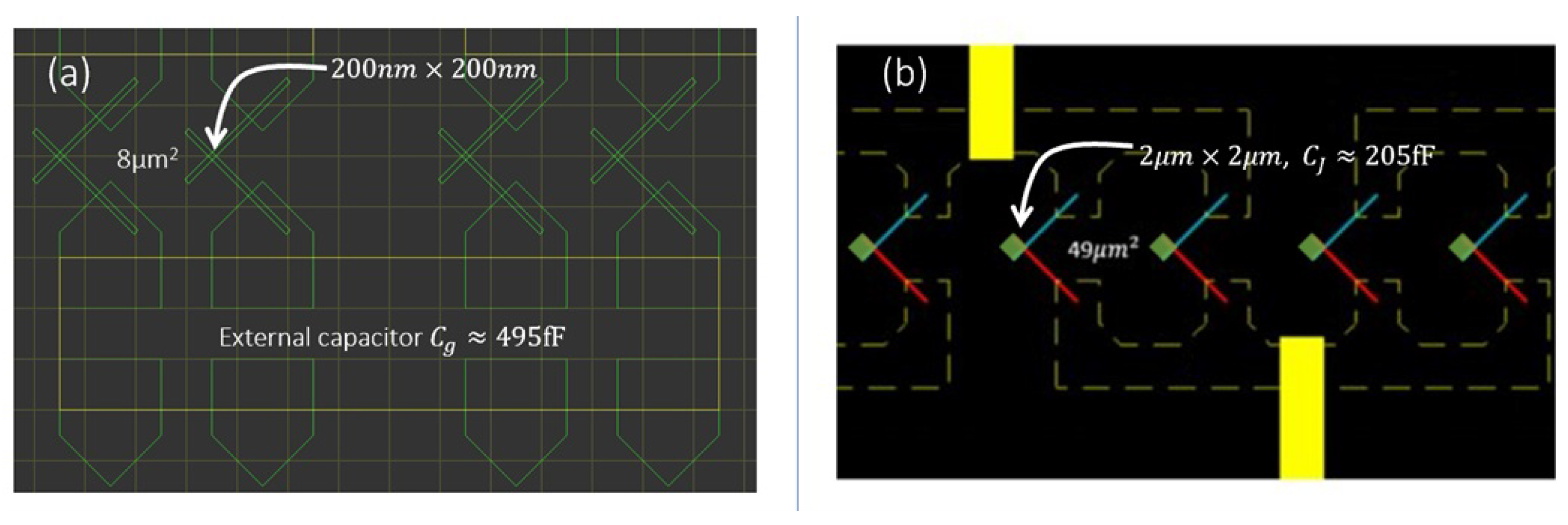
The Josephson junctions in this work were fabricated by the Manhattan pattern technique with multi-angle deposition of Al electrodes through a bilayer e-beam resist mask [43]. The oxidation process performed between depositions of the bottom and top aluminum electrodes has been optimized for fabrication of junctions with required values of E J and minimal scattering of junction parameters. Typically, the dry oxygen partial pressure 1 100 torr and oxidized the structures for 5–15 min were used. The standard deviation of the normal state resistance R N across the 7 mm × 7 mm chip did not exceed 10 % for sub- μ m-wide junctions with R N 1 k Ω and 30 % for the junctions with R N 100 k Ω . The junction area variations did not exceed 10 % across a 200 μ m-long chain.
All the samples studied in this work have been implemented as SQUIDs, in order to be able to in-situ tune E J by applying the external magnetic field. Figure A1 schematically shows the design of a chain of SQUIDs formed by small junctions ( 0.2 × 0.2 μ m 2 ). The area of the SQUID loop varied between 6 μ m 2 and 49 μ m 2 . In this work, the experiments are focused on the JJs with 1 K > E J E C ; this regime is relevant to the quantum circuits in which JJs are shunted with large external capacitors (such as the transmon qubit). Large E J / E C ratio also significantly reduces the rate of quantum phase slips Γ Q P S e x p ( 2 E J / E C ) [13]. The specific capacitance of the tunneling A l O X barrier is about 50 fF/ μ m 2 , and in order to reduce E C down to ∼10 mK, the junctions should either have relatively large in-plane dimensions ( A J J > 4 μ m 2 ) or be shunted with external capacitors ( C g > 200 fF). Both methods are used in different structures. In the approach where relatively large JJs are introduced in order to keep E J below 1 K, the oxidation recipes are fine-tuned for the growth of low-transparency tunneling A l O X barrier. In the “external capacitor” approach, several designs of the shunting capacitors have been implemented. Figure A1 shows that each SQUID unit cell is flanked by two large metal pads, which are used as shunting capacitors C g to the common ground when the entire chain was covered by an additional top electrode (sputtered P t film). A few n m thick native A l O X oxide grown at the atmospheric pressure serves as a pinhole-free dielectric for this parallel-plate C g with a typical capacitance around 500 fF for 50 μ m 2 pad area. Such C g corresponds to a charging energy per each cell as low as E C = ( 2 e ) 2 / 2 C = 8 mK.
Figure A1. Various designs of SQUIDs. (a) Each SQUID unit cell was shunted by a large C g 0 . 5 pF the ground. The common ground electrode is shown by a yellow rectangle. (b) SQUIDs formed by large JJs with junction area A JJ 2 . 2 μ m 2 . Yellow rectangles show electrodes used to measure the IVC of individual SQUIDs.
Electronics 12 00416 g0a1

Appendix B. Measurement Setup

To measure the IVC of low- E J junctions with small switching currents (typically, within the pA-nA range), careful filtering of noise in the measurement circuit is required (see, e.g., [25]). Our measurement setup included the cascaded low pass filters shown in Figure A2. The wiring for DC setup inside the cryostat consists of 12 twisted pairs made of resistive alloys C u N i : N b T i (5:1) with multiple thermal anchoring points. Near the cold finger which supported the sample holder, about 1-meter-long twisted pairs are used as central conductors of the copper-powder-epoxy lowpass filter with the cut-off frequency ∼100 MHz (see, e.g., [44]); this filter also provides thermal anchoring of all wires before connecting to the sample. On the sample holder, 100 k Ω surface mount metal-film resistors with low parasitic capacitance have been installed in each lead. The voltage across the sample was amplified by a preamplifier (DL Instrument 1201) with a few G Ω input impedance.
The circuit outside of the dilution refrigerator (Figure A2) included a commercial LC low pass filter (BLP 1.9+, DC 1.9 MHz) and a homemade RC filter (DC 8 Hz) box with variable biasing resistors up to 1 G Ω . The voltage drop across the sample was amplified with a voltage preamp DL1201 and measured by HP 34401A digital multimeter.
Figure A2. The wiring schematics for DC current source measurements. The device-under-test (DUT) was mounted inside a sample holder thermally anchored to the mixing chamber of the dilution refrigerator.
Electronics 12 00416 g0a2

Appendix C. The Effect of Noise on the Current-Voltage Characteristics
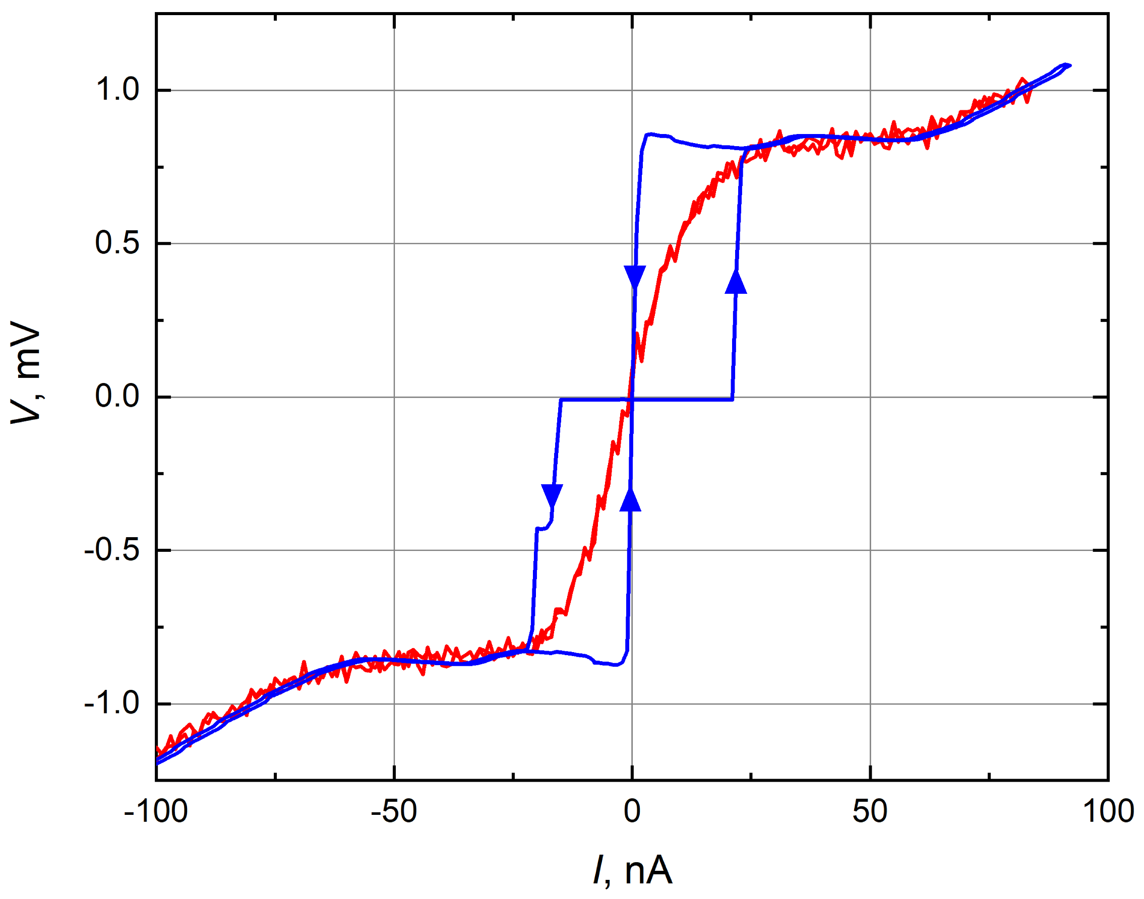
In this work, the noise reduction is the primary concern in characterization of low- E J junctions, and most of the measurements have been performed in the constant current mode. According to Equation (1), I C A B = 30 nA at T = 0 for an A l / A l O x / A l JJ with E J = 1 K. With further reduction of E J and increase of the phase slip rate, the current range well below 1 nA becomes relevant.
Figure A3 illustrates the importance of proper filtering of noises in both the current supply part and the voltage recording part of the measuring setup. By using the combination of cascaded low-pass filters and 100 k Ω resistors on the sample holder, switching currents in the pA range precision are achieved (Figure 1c of the main text).
Figure A3. The IVC recorded for a two-unit SQUID device with different measurement setups at T = 25 mK (sample 3 in Table 1). Without thorough filtering, the IVC was non-hysteretic and smeared. Proper filtering of all leads enables observation of a well-developed hysteresis expected for an underdamped junction at low T.
Electronics 12 00416 g0a3

Appendix D. Modeling the Effect of Thermal Noise
The theory of the DC transport in underdamped Josephson junctions in presence of a stochastic noises has been developed by Ivanchenko and Zilberman [28]. According to the Ivanchenko–Zilberman (IZ) model, a voltage-biased Josephson junction is subject to thermal noise of the biasing resistor which causes phase diffusion (see Equation (4) in the main text). By solving the corresponding Fokker–Planck equation, the superconducting part of the current as a function of bias voltage V B can be found as:
I S = I C × I m [ J 1 i α ν ( α ) J i α ν ( α ) ] ,
where α = E J k B T , ν = V B I C R and J a + i b is the modified Bessel function. In the limit of a small Josephson energy E J k B , this expression is simplified:
I S = I C R 2 V B V B 2 + V n 2
V n = 2 e R k B T
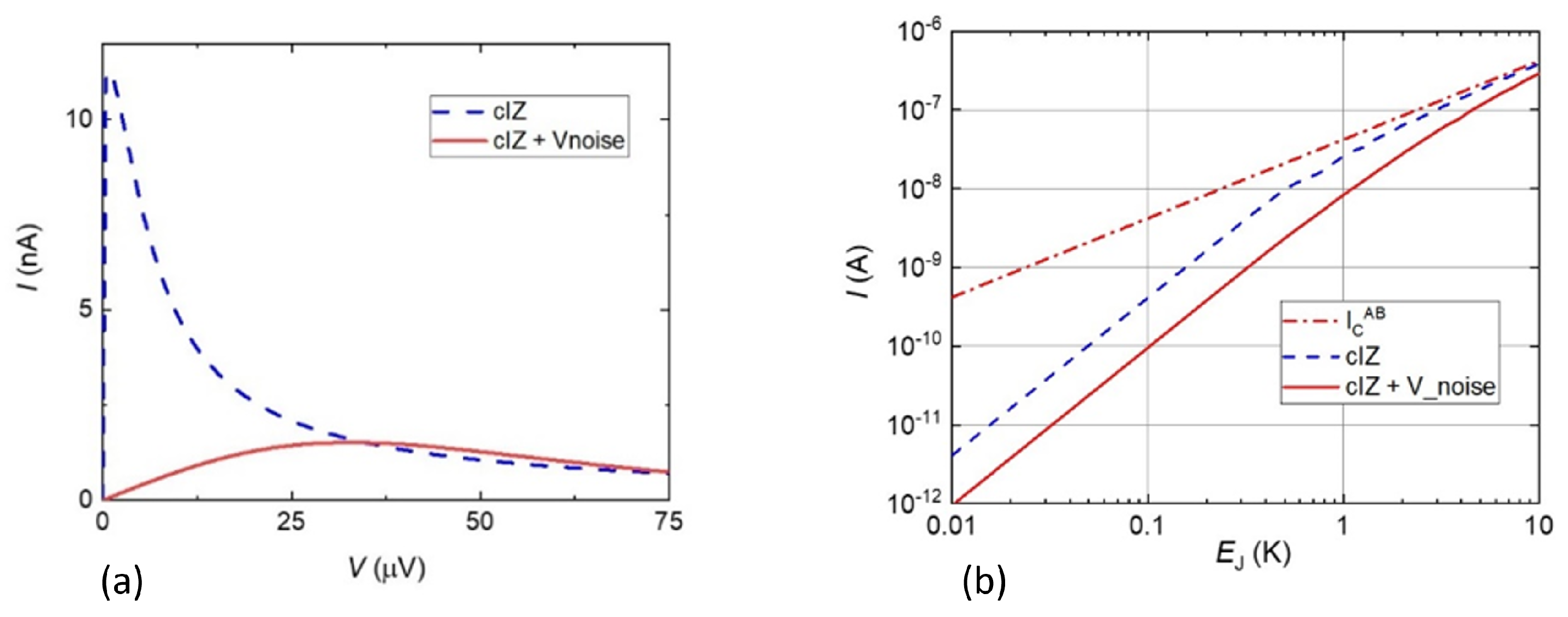
The maximum current that can be carried by Cooper pairs is realized at V B = V n ( V n is the Johnson noise from the resistor R); the further increase of the biasing current leads to switch to the resistive state. As Figure A4b shows, the value of the switching current predicted by the classical IZ (cIZ) model starts to deviate from I C A B for the junction with E J < 1 K. The maximum value of the switching current is realized at a non-zero voltage V n , which depends only on the voltage noise amplitude, so the zero-bias resistance in the IPS regime is expected to scale as E J 2 .
In the case when a system is subject to other sources of noise such as the thermal noise across the junction capacitance or the external electromagnetic noise due to insufficient filtering, the modified IVC can be calculated by convolving the cIZ curve with Gaussian-distributed V B of the width corresponding to the noise amplitude V n o i s e (Figure A4a,b). As Figure A4b shows, the cIZ model can explain qualitatively the switching current behavior in systems with low Josephson energy, the value of the excessive noise V n o i s e could be used as a fitting parameter to obtain quantitative agreement.
Figure A4. (a) The supercurrent branch of the IVC of a JJ with E J = 1 K at T = 50 mK, predicted by the classical IZ theory (dashed line) and its modification in presence of gaussian noise with amplitude 24 μ V (solid line). (b) Nominal critical current (dot-dashed line), switching current according to the IZ theory without (dashed line) and with (solid line) extra voltage noise of the same amplitude.
Electronics 12 00416 g0a4

References

  1. Nguyen, L.B.; Lin, Y.-H.; Somoroff, A.; Mencia, R.; Grabon, N.; Manucharyan, V.E. High-Coherence fluxonium qubit. Phys. Rev. X 2019, 9, 041041. [Google Scholar] [CrossRef] [Green Version]
  2. Gyenis, A.; Mundada, P.S.; Paolo, A.D.; Hazard, T.M.; You, X.; Schuster, D.I.; Koch, J.; Blais, A.; Houck, A.A. Experimental realization of a protected superconducting circuit derived from the 0–π qubit. PRX Quantum 2021, 2, 010339. [Google Scholar] [CrossRef]
  3. Zhang, H.; Chakram, S.; Roy, T.; Earnest, N.; Lu, Y.; Huang, Z.; Weiss, D.K.; Koch, J.; Schuster, D.I. Universal fast-flux control of 387 a coherent, low-frequency qubit. Phys. Rev. X 2021, 11, 011010. [Google Scholar]
  4. Peruzzo, M.; Trioni, A.; Hassani, F.; Zemlicka, M.; Fink, J.M. Surpassing the resistance quantum with a geometric superinductor. Phys. Rev. Appl. 2020, 14, 044055. [Google Scholar] [CrossRef]
  5. Somoroff, A.; Ficheux, Q.; Mencia, R.A.; Xiong, H.; Kuzmin, R.V.; Manucharyan, V.E. Millisecond coherence in a superconducting qubit. arXiv 2021, arXiv:2103.08. [Google Scholar]
  6. Tinkham, M. Introduction to Superconductivity; Dover Publications: Mineola, NY, USA, 1996. [Google Scholar]
  7. Martinis, J.M.; Kautz, R.L. Classical phase diffusion in small hysteretic Josephson junctions. Phys. Rev. Lett. 1989, 63, 1507–1510. [Google Scholar] [CrossRef]
  8. Kautz, R.L.; Martinis, J.M. Noise-affected i-v curves in small hysteretic Josephson junctions. Phys. Rev. B 1990, 42, 9903. [Google Scholar] [CrossRef]
  9. Eiles, T.M.; Martinis, J.M. Combined Josephson and charging behavior of the supercurrent in the superconducting singleelectron transistor. Phys. Rev. B 1994, 50, 627–630. [Google Scholar] [CrossRef]
  10. Watanabe, M.; Haviland, D.B. Quantum effects in small-capacitance single Josephson junctions. Phys. Rev. B 2003, 67, 094505. [Google Scholar] [CrossRef] [Green Version]
  11. Fazio, R.; van der Zan, H. Quantum phase transitions and vortex dynamics in superconducting networks. Phys. Rep. 2001, 355, 235–334. [Google Scholar] [CrossRef] [Green Version]
  12. Bard, M.; Protopopov, I.V.; Gornyi, I.V.; Shnirman, A.; Mirlin, A.D. Superconductor-insulator transition in disordered Josephson-junction chains. Phys. Rev. B 2017, 96, 064514. [Google Scholar] [CrossRef] [Green Version]
  13. Ast, C.R.; Jäck, B.; Senkpiel, J.; Eltschka, M.; Etzkorn, M.; Ankerhold, J.; Kern, K. Sensing the quantum limit in scanning tunnelling spectroscopy. Nat. Commun. 2016, 7, 13009. [Google Scholar] [CrossRef] [PubMed]
  14. Murani, A.; Bourlet, N.; Sueur, H.; Portier, F.; Altimiras, C.; Esteve, D.; Grabert, H.; Stockburger, J.; Ankerhold, J.; Joyez, P. Absence of a dissipative quantum phase transition in Josephson junctions. Phys. Rev. X 2020, 10, 021003. [Google Scholar] [CrossRef] [Green Version]
  15. Matveev, K.A.; Larkin, A.I.; Glazman, L.I. Persistent Current in Superconducting Nanorings. Phys. Rev. Lett. 2002, 89, 096802. [Google Scholar] [CrossRef] [Green Version]
  16. Manucharyan, V.E.; Masluk, N.A.; Kamal, A.; Koch, J.; Glazman, L.I.; Devoret, M.H. Evidence for coherent quantum phase slips across a Josephson junction array. Phys. Rev. B 2012, 85, 024521. [Google Scholar] [CrossRef] [Green Version]
  17. Koch, J.; Yu, T.M.; Gambetta, J.; Houck, A.A.; Schuster, D.I.; Majer, J.; Blais, A.; Devoret, M.H.; Girvin, S.M.; Schoelkopf, R.J. Charge-insensitive qubit design derived from the Cooper pair box. Phys. Rev. A 2007, 76, 042319. [Google Scholar] [CrossRef] [Green Version]
  18. Gyenis, A.; Paolo, A.D.; Koch, J.; Blais, A.; Houck, A.A.; Schuster, D.I. Moving beyond the transmon: Noise-Protected superconducting quantum circuits. PRX Quantum 2021, 2, 030101. [Google Scholar] [CrossRef]
  19. Earnest, N.; Chakram, S.; Lu, Y.; Irons, N.; Naik, R.K.; Leung, N.; Ocola, L.; Czaplewski, D.A.; Baker, B.; Lawrence, J.; et al. Realization of a Λ system with metastable states of a capacitively shunted fluxonium. Phys. Rev. Lett. 2018, 120, 150504. [Google Scholar] [CrossRef] [Green Version]
  20. Mooij, J.E.; Nazarov, Y.V. Superconducting nanowires as quantum phase-slip junctions. Nat. Phys. 2006, 2, 169–172. [Google Scholar] [CrossRef]
  21. Astafiev, O.V.; Ioffe, L.B.; Kafanov, S.; Pashkin, Y.A.; Arutyunov, K.Y.; Shahar, D.; Cohen, O.; Tsai, J.S. Coherent quantum phase slip. Nature 2012, 484, 355. [Google Scholar] [CrossRef] [Green Version]
  22. Svetogorov, A.E.; Taguchi, M.; Tokura, Y.; Basko, D.M.; Hekking, F.W.J. Theory of coherent quantum phase slips in Josephson junction chains with periodic spatial modulations. Phys. Rev. B 2018, 97, 104514. [Google Scholar] [CrossRef] [Green Version]
  23. Arutyunov, K.Y.; Golubev, D.S.; Zaikin, A.D. Superconductivity in one dimension. Phys. Rep. 2008, 464, 1–70. [Google Scholar] [CrossRef]
  24. Semenov, A.G.; Zaikin, A.D. Quantum phase slip noise. Phys. Rev. B 2016, 94, 014512. [Google Scholar] [CrossRef] [Green Version]
  25. Schön, G.; Zaikin, A.D. Quantum coherent effects, phase transitions, and the dissipative dynamics of ultra small tunnel junctions. Phys. Rep. 1990, 198, 237–412. [Google Scholar] [CrossRef]
  26. Vion, D.; Götz, M.; Joyez, P.; Esteve, D.; Devoret, M.H. Thermal activation above a dissipation barrier: Switching of a small Josephson junction. Phys. Rev. Lett. 1996, 77, 3435–3438. [Google Scholar] [CrossRef] [PubMed] [Green Version]
  27. Fistul, M.V. Josephson phase diffusion in small josephson junctions: A strongly nonlinear regime. In No-Nonsense Physicist; Polini, M., Vignale, G., Pellegrini, V., Jain, J.K., Eds.; Publications of the Scuola Normale Superiore; Edizioni della Normale: Pisa, Italy, 2016; Volume 2, pp. 73–80. [Google Scholar]
  28. Ivanchenko, Y.M.; Zil’berman, L.A. The Josephson effect in small tunnel contacts. Sov. Phys. JETP 1969, 28, 1272. [Google Scholar]
  29. Shimada, H.; Katori, S.; Gandrothula, S.; Deguchi, T.; Mizugaki, Y. Bloch oscillation in a one-dimensional array of small Josephson junctions. J. Phys. Soc. Jpn. 2016, 85, 074706. [Google Scholar] [CrossRef]
  30. Kivioja, J.M.; Nieminen, T.E.; Claudon, J.; Buisson, O.; Hekking, F.W.J.; Pekola, J.P. Observation of transition from escape dynamics to underdamped phase diffusion in a Josephson junction. Phys. Rev. Lett. 2005, 94, 247002. [Google Scholar] [CrossRef] [Green Version]
  31. Lu, W.-S. Josephson Circuits for Protected Quantum Bits. Ph.D. Thesis, Rutgers University, New Brunswick, NJ, USA, 2021. [Google Scholar]
  32. McCumber, D.E. Effect of ac impedance on dc Voltage-Current characteristics of superconductor Weak-Link junctions. J. Appl. Phys. 1968, 39, 3113–3118. [Google Scholar] [CrossRef]
  33. Schmidlin, S. Physics and Technology of Small Josephson Junctions. Ph.D. Thesis, Royal Holloway, University of London, Egham, UK, 2013. [Google Scholar]
  34. Coon, D.D.; Fiske, M.D. Josephson ac and step structure in the supercurrent tunneling characteristic. Phys. Rev. 1965, 138, A744–A746. [Google Scholar] [CrossRef]
  35. Wilen, C.D.; Abdullah, S.; Kurinsky, N.A.; Stanford, C.; Cardani, L.; D’Imperio, G.; Tomei, C.; Faoro, L.; Ioffe, L.B.; Liu, C.H.; et al. Correlated charge noise and relaxation errors in superconducting qubits. Nature 2021, 594, 369–373. [Google Scholar] [CrossRef] [PubMed]
  36. Weißl, T.; Rastelli, G.; Matei, I.; Pop, I.M.; Buisson, O.; Hekking, F.W.J.; Guichard, W. Bloch band dynamics of a Josephson junction in an inductive environment. Phys. Rev. B 2015, 91, 014507. [Google Scholar] [CrossRef] [Green Version]
  37. Senkpiel, J.; Dambach, S.; Etzkorn, M.; Drost, R.; Padurariu, C.; Kubala, B.; Belzig, W.; Yeyati, A.L.; Cuevas, J.C.; Ankerhold, J.; et al. Single channel Josephson effect in a high transmission atomic contact. Commun. Phys. 2020, 3, 1–6. [Google Scholar] [CrossRef]
  38. Jäck, B. Josephson Tunneling at the Atomic Scale. Ph.D. Thesis, EPFL, Lausanne, Switzerland, 2015. [Google Scholar]
  39. Yeh, S.-S.; Chen, K.-W.; Chung, T.-H.; Wu, D.-Y.; Lin, M.-C.; Wang, J.-Y.; Ho, I.-L.; Wu, C.-S.; Kuo, W.; Chen, C. A method for determining the specific capacitance value of mesoscopic Josephson junctions. Appl. Phys. Lett. 2012, 101, 232602. [Google Scholar] [CrossRef]
  40. Jäck, B.; Senkpiel, J.; Etzkorn, M.; Ankerhold, J.; Ast, C.R.; Kern, K. Quantum brownian motion at strong dissipation probed by superconducting tunnel junctions. Phys. Rev. Lett. 2017, 119, 147702. [Google Scholar] [CrossRef] [Green Version]
  41. Kuzmin, L.S.; Nazarov, Y.V.; Haviland, D.B.; Delsing, P.; Claeson, T. Coulomb blockade and incoherent tunneling of cooper pairs in ultrasmall junctions affected by strong quantum fluctuations. Phys. Rev. Lett. 1991, 67, 1161–1164. [Google Scholar] [CrossRef] [PubMed]
  42. Manucharyan, V. Private Communication, 2020.
  43. Bell, M.T.; Sadovskyy, I.A.; Ioffe, L.B.; Kitaev, A.Y.; Gershenson, M.E. Quantum superinductor with tunable nonlinearity. Phys. Rev. Lett. 2012, 109, 137003. [Google Scholar] [CrossRef] [Green Version]
  44. Martinis, J.M.; Devoret, M.H.; Clarke, J. Experimental tests for the quantum behavior of a macroscopic degree of freedom: The phase difference across a Josephson junction. Phys. Rev. B 1987, 35, 4682–4698. [Google Scholar] [CrossRef]
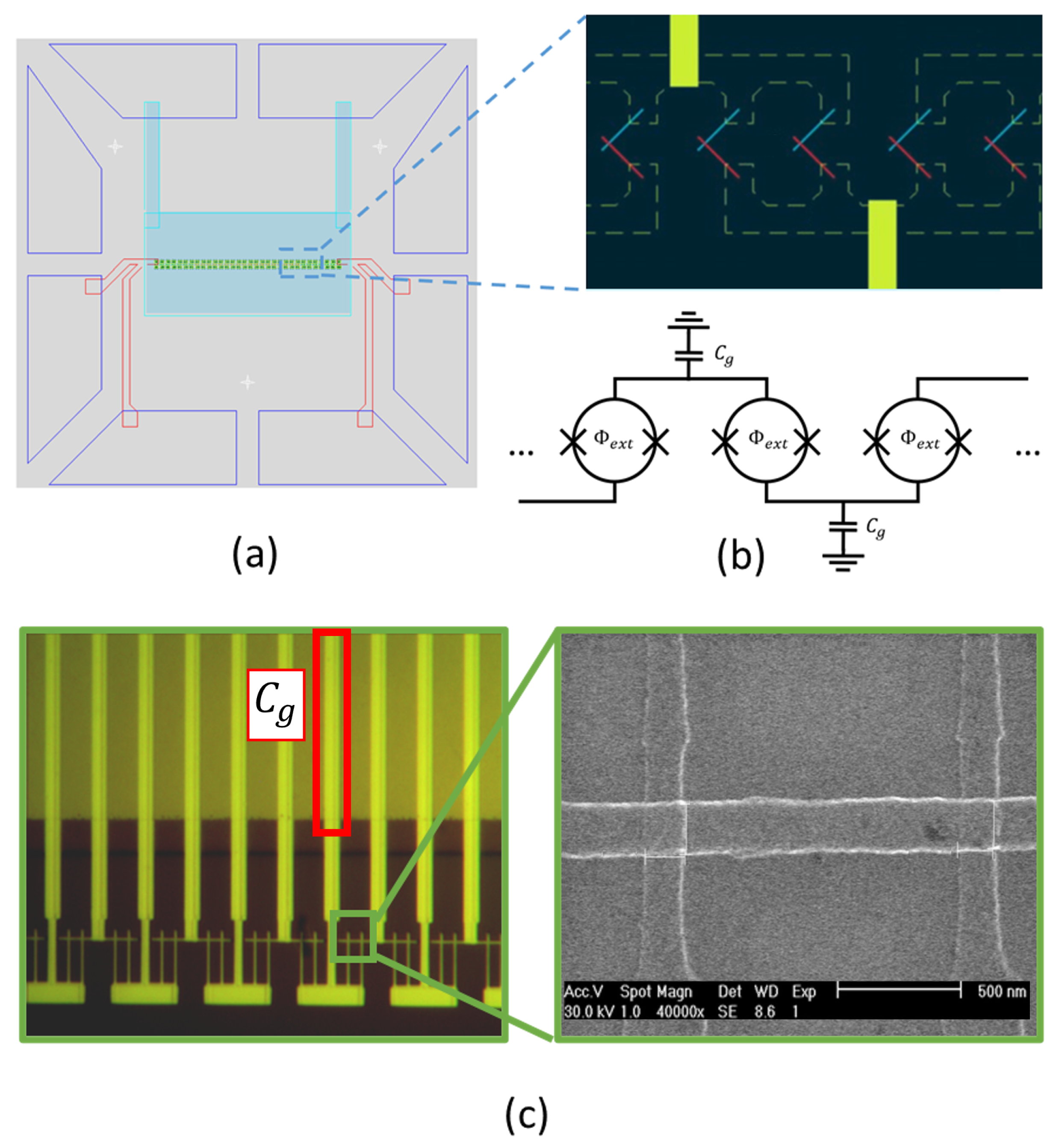
Figure 1. (a) Current-voltage characteristics of two connected-in-series SQUIDs at Φ = 0 (blue curve) and Φ = 0.5 Φ 0 (red curve) at T 30 mK. Each SQUID is formed by two nominally identical JJs with E J = 0.76 K (sample 3 in Table 1), thus the SQUID Josephson energy is 1.52   K . Even for this circuit with relatively high E J , the measured switching current per junction, I S W = 9 nA, is significantly lower than I C A B = 33 nA. (b) The IVC of a chain of 20 SQUIDs with E J = 80 mK (for single-JJ parameters, see sample 6 in Table 1). (c) The enlargement of the region of small currents/voltages in panel (b). Note that the resistance is non-zero for all biasing currents. The switching current (its value for a given sample, 0.6 pA, is indicated by an arrow) corresponds to a rapid increase of the voltage across the chain. This switching current is almost four orders of magnitude smaller than the I C A B value for this sample (see Table 1). The zero-bias resistance ( R 0 500 M Ω per junction) was determined as the slope of the IVC at I I S W .
Electronics 12 00416 g001
Figure 2. (a) Schematics of a chain of SQUIDs made of Josephson junctions with a relatively large area (i.e., large C J ) and a low transparency of the tunneling barrier (i.e., small E J ). The common ground electrode made of a sputtered Pt film is shown in pale blue. A few n m thick A l O X oxide covers this electrode and serves as a pinhole-free dielectric that isolates the ground from the SQUIDs. The typical value of the capacitance that shunts a single SQUID, C g , is 0.5 nF for 50 μ m 2 pad area. This C g corresponds to a charging energy per SQUID E C = ( 2 e ) 2 2 C g = 8 mK. (b) The circuit diagram of a chain of SQUIDs. (c) An alternative design of a chain of SQUIDs shunted by external capacitors to the ground. The vertical 5 μ m-wide pads are the ground electrodes for the capacitors, a few n m thick A l O X serves as a dielectric between the electrodes.
Electronics 12 00416 g002
Figure 3. (a) Current-voltage characteristics of two connected in series SQUIDs measured at Φ = 0.5 Φ 0 and different temperatures (from 30 mK to 560 mK, as shown in the panel). The SQUIDs are formed by JJs with E J = 0.76 K (sample 3 in Table 1). (b) The temperature dependence of the zero-bias resistance for this sample. The red dashed line corresponds to the dependence R 0 ( Φ = 0.5 Φ 0 , T ) = 4 k Ω × exp ( δ / T ) with δ = 2.1 K.
Electronics 12 00416 g003
Figure 4. (a) Current-voltage characteristics of a single SQUID formed by JJs with E J = 2.4 K (sample 2 in Table 1) measured at different values of Φ / Φ 0 = 0 , 0.08 , 0.17 , 0.25 , 0.37 , 0.5 . A sub-gap voltage plateau at V 75 μ V appears at Φ > 0.35 Φ 0 . For different samples the sub-gap voltage plateau was observed at V = 40–200 μ V. (b) The dependence of I S W on the magnetic field B. (c) The measured I S W ( Φ ) / I S W ( Φ = 0 ) as a function of c o s ( π Φ / Φ 0 ) . The dashed line corresponds to the dependence I S W c o s ( π Φ / Φ 0 ) .
Electronics 12 00416 g004
Figure 5. The switching current I S W as a function of E J measured in experiments conducted in this work (the color-coded symbols, the sample numbers correspond to that in Table 1) and by other experimental groups (black dots, the references are given in square brackets). All the data have been obtained at T 20–50 mK for A l / A l O X / A l junctions. For the values of I S W measured at B 0 the Josephson energy E J ( B ) was calculated using Equation (2). The dashed red line corresponds to the Ambegaokar–Baratoff dependence I C A B ( E J ) (Equation (1)), the solid red curve—to the switching current predicted by the IZ theory in presence of additional V n o i s e = 24 μ V generated by the biasing scheme (see Appendix D).
Electronics 12 00416 g005
Figure 6. The zero-bias resistance R 0 as a function of E J measured for a chain of SQUIDs made of JJs with E J = 0.43 K (sample 5 in Table 1) (red dots). For comparison, the values of R 0 measured by other experimental groups for A l / A l O X / A l junctions (black dots, the references are given in square brackets) are also plotted, the parameters of these samples are listed in Table 2. All the data have been obtained at the base T < 50 mK, though the physical temperature of the Josephson circuits has not been directly measured. The Josephson energy E J ( B ) for sample 5 was calculated using Equation (2).
Electronics 12 00416 g006
Table 1. Parameters of single Josephson junctions in SQUID chains. R N and A J J are the normal-state resistance and the junction area, respectively. The Josephson energy E J = π Δ / ( ( 2 e ) 2 R N ) has been calculated using R N and T C = 1.3 K. The charging energy E C , where C is the shunting capacitance, did not exceed 10 mK for all samples. The critical current I C A B was calculated using Equation (1).
Sample R N (k Ω ) E J (K) A JJ ( μ m 2 ) I C AB I SW (nA)
12.42.91.913048
22.92.43.7410768
39.40.760.04339
415.80.450.04200.3
516.60.430.04190.1
61750.040.041.80.003
Disclaimer/Publisher’s Note: The statements, opinions and data contained in all publications are solely those of the individual author(s) and contributor(s) and not of MDPI and/or the editor(s). MDPI and/or the editor(s) disclaim responsibility for any injury to people or property resulting from any ideas, methods, instructions or products referred to in the content.