Article

Investigation of Spindt Cold Cathode Electron Guns for Terahertz Traveling Wave Tubes

1
School of Mechanical and Automotive Engineering, Guangxi University of Science and Technology, Liuzhou 545006, China
2
School of Automation, Guangxi University of Science and Technology, Liuzhou 545006, China
3
Beijing Vacuum Electronics Research Institute, Beijing 100015, China
*
Author to whom correspondence should be addressed.
Electronics 2023, 12(20), 4197; https://doi.org/10.3390/electronics12204197
Submission received: 18 August 2023 / Revised: 18 September 2023 / Accepted: 28 September 2023 / Published: 10 October 2023

Abstract

:
In this work, a Spindt cold cathode electron gun with a PPM (periodic permanent magnet) focusing system for a terahertz TWT (traveling wave tube) was designed and simulated based on the Pierce electron gun structure. More specifically, a new 3D (three dimensional) emission model was used, where the cathode radius of the electron gun was 1 mm and the cathode current was 30 mA, with an emitting half angle of about 28°. It was demonstrated that the electron beam was well focused with an electron beam radius of 0.3 mm and a filling ratio of 0.5 when the maximum value of the PPM field along with the axis was 0.122T. According to the simulation results, a planar cold cathode electron gun was developed. Measurements demonstrated that the I/V characteristics of the cold cathode gun were consistent with that of a cold cathode, revealing that the electrons emitted from the cathode are not intercepted when passing through the electron gun.

1. Introduction

High-frequency vacuum devices have received considerable attention from the scientific community owing to their promising applications in various applications, including broadband communication, radar, medical imaging, and so on [1,2,3]. In particular, a vacuum device for radar consists of an electron gun assembly with a cathode, a slow wave structure (SWS) with both an output and input coupler, a magnetic field system, and a collector. For terahertz TWTs, electron guns have to emit a sufficient number of electrons to amplify terahertz signals. In addition, Spindt cold cathodes have a high current density emission, long lifetime, and low operating voltage, which render them an attractive candidate for fabricating thermionic emitters for terahertz vacuum devices [4,5]. In addition, the modulation of the input signals with gated cathodes at microwave frequencies directly allows for the development of current density-modulated electron beams, thus resulting in a significant reduction in the length of linear beam devices, as well as the volume and weight of terahertz TWTs [6,7]. Terahertz TWTs operating in the modulated or unmodulated mode exhibit greatly expanded I/V operation space over that of a thermionic TWT. However, the Spindt cold cathode consists of Mo tips, which exhibit some undesirable features [8,9]. Electrons emitted from a tip have divergences of up to 28° and can easily bombard electrodes, such as anode electrodes. In addition, unlike the thermionic cathode, the surface of the FEA (field emitting array) cathode is flat, not spherical. Thus, the generated space charge force created by the high current density induces the divergence of the electron beam. Another critical issue that needs to be addressed is the ion back-bombardment. Due to the ionization of the residual gas in the TWT, ions are produced that interact with the electric field and are accelerated by the application of the large negative voltage at the cathode surface. Afterward, these ions bombard the surfaces of the Mo tips with sufficient energy. As a result, they will be damaged and the electron emissions at the damaged surfaces may possibly be suppressed.
Although the application of FEA (field emitters array) cold cathodes in TWTs faces many problems, this issue has still been investigated in the literature. Whaley et al. used the MAGIC software package to design a cold cathode electron gun with current values of 0 < I < 0.15 A. The authors incorporated a PPM-focused system and achieved circuit efficiencies of 50% for the minimal bunching of average-to-peak current ratios of 0.7–0.9 [6]. Moreover, NEC also designed an electron gun with excellent focusing performance. The flow rate of the TWT was 99.3% at an electron injection current of 56 mA, and the output power was 28.2 W at a center frequency of 11.5 GHz with an efficiency of 10% [10]. Under certain conditions, the geometry of the Pierce electron gun can be used to focus the electron beams of the planar cathodes. In the investigations described above, the larger thermionic emitters were used to replace FEA emitters to simulate electron gun geometry for focusing and confining FEA-generated electron beams without considering the perpendicular velocities of the electrons. In this work, a new 3D computational model was used to optimize the cold cathode electron gun and the PPM structures applied in the TWT to effectively overcome the initial transverse velocity of the emitted electrons and form a laminar and parallel electron beam.

2. Theoretical Design

Whaley et al. [6] have directly placed a planar cold cathode into a Pierce electron gun instead of a convergent thermionic cathode and studied the focusing and confinement effect of an electron beam generated by the cold cathode. From the acquired experimental results, it can be seen that Pierce electron guns can focus an electron beam well, even at low current densities. Once the current density exceeded a certain threshold, the electron beam scattered and bombarded the anodes or tube walls. At 40 mA, the electron beam started to expand due to space charge forces. Next, at 100 mA, the electron beam exhibited zero transmission and clearly demonstrated the need for the development of a new type of cold cathode electron gun. The electron current of the electron gun in this work was 30 mA. From the above-mentioned analysis, it can be inferred that the geometry of the Pierce electron gun can be used for focusing the cold cathode electron gun on the low emitted electron current.
Based on the Pierce electron gun geometry and the PPM system, each dimension and parameter of the electron gun and the PPM stacks were thoroughly designed and optimized to acceptably obtain the focusing of the electron beam, including positions, shape, and applied voltages of each electrode, as well as the amplitude of the PPM magnetic field. On this basis, the variation of the electron beam parameters was examined and the relationship between the electron beam focusing characteristics, the operating current, and the variation of the magnetic field amplitude was investigated.

2.1. Cold Cathode

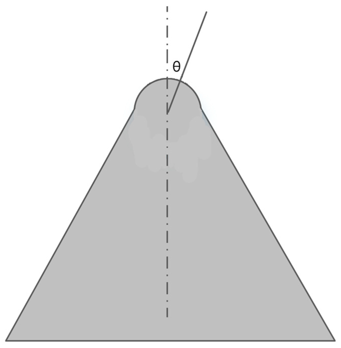
The Spindt cold cathode essentially consisted of Mo (Molybdenum) emitters, a Mo gate film, a SiO2 (Silicon Dioxide) layer, and a Si (Silicon) wafer, shown in Figure 1. The Mo gate film had holes of 1 μm in diameter in it, through which cavities were etched into the SiO2 layer with the thickness of 0.6 μm. Mo emitters with heights of 0.9 μm were deposited into the cavities via electron beam evaporation. The Spindt cold cathode used in the terahertz TWT consisted of 13,000 Mo emitting tips arranged in a circular area of 0.6 mm in diameter, shown in Figure 1 [11]. The emitter can be modeled as a hemisphere with a radius of 25 nm centered at the apex of a cone, as shown in Figure 2. The field emission current can be derived from the Fowler–Nordheim equation as a function of the applied electric field at the emitting surface [4,12].
J = A E 2 ϕ t 2 ( y ) e x p ( B ϕ 3 / 2 E v ( y ) )
where A and B are the approximate Fowler–Nordheim constants, A = 1.5 × 10 6 ,   B = 6.87 × 10 7 , t ( y ) and v ( y ) are elliptical functions of the variable y = 3.79 × 10 4 E 1 / 2 / ϕ , E is the electric field at the emitting surface in V/cm, J denotes the emission current density in A/cm2, ϕ refers to the material work function in eV, and y stands for the Schottky lowering of the work function barrier.
The total emitting current from a single-tip emitter is obtained through the following expression:
I ( V ) = α J [ E ( V ) ]
where α is the effective emitting area. The effective emitting area can be defined by an emitting half angle ( θ ), where the electric field has reduced by 10% [4] and where θ   is the angle of the symmetry axis to the cone emitter, as shown in Figure 2.
The electric field E ( θ ) , where θ represents the emitting half angle, can be written as follows [13,14,15,16]:
E ( θ ) = E 0 / ( 1 + f 2 ( θ ) t a n 2 ( θ ) ) 1 / 2
f ( θ ) = 1 ± 1 + 2 t a n 2 ( θ )         :   θ 90 ° ; + : θ 90 °  
where E 0 is the electric field at the apex of the Mo tip.
According to Equation (3), the variation of the electric field ( E ( θ ) ) with the emitting half angle ( θ ) is plotted in Figure 3. As can be observed, at the emitting half angle of about 28°, E ( θ ) was decreased by 10% from the value ( E 0 ) at the apex, while J was reduced by about 90%, which is consistent with the experimental outcomes.
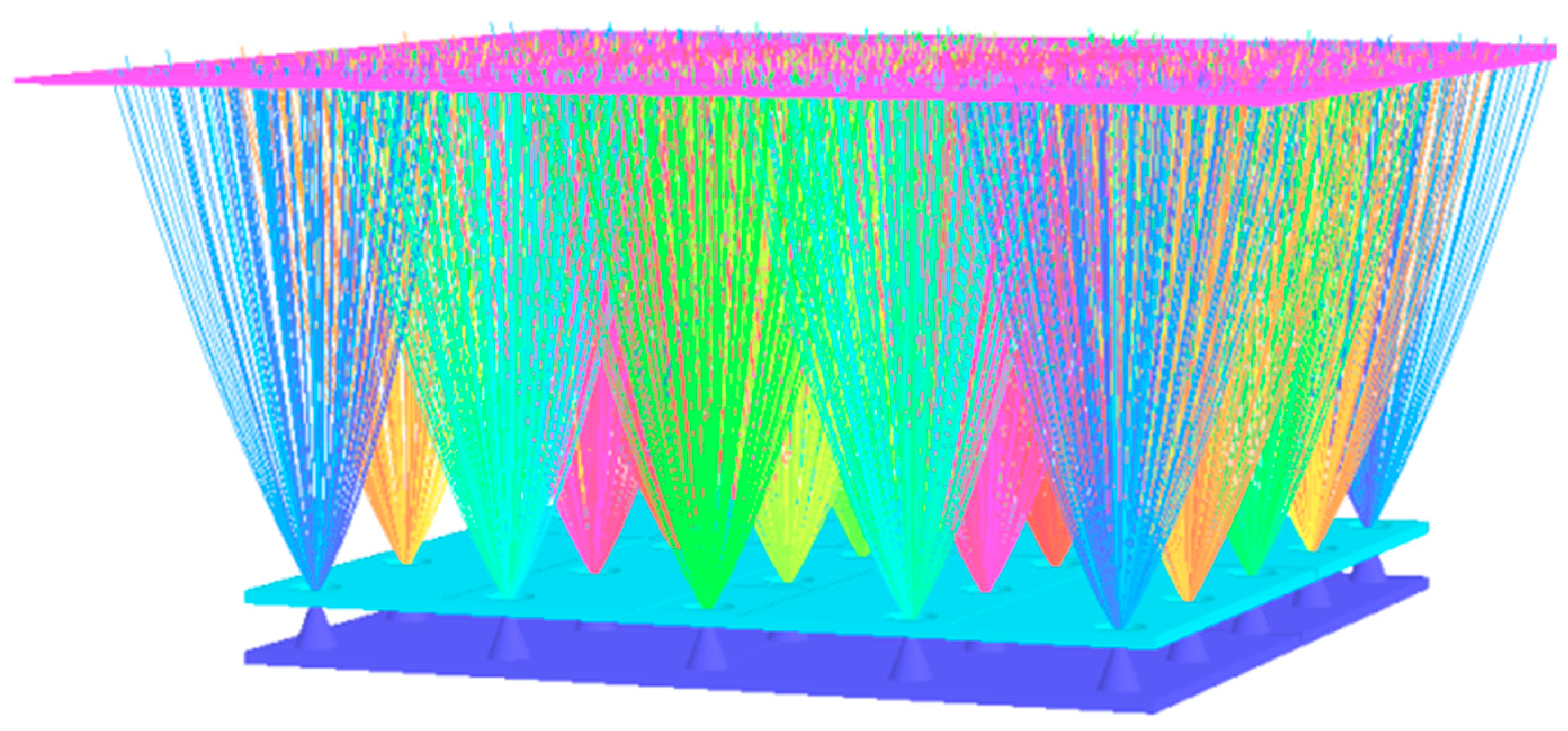
In order to understand the field distribution along the emitter and electron trajectories, the Spindt field emitting arrays cathode in the triode mode was also simulated using Opera-3D [17,18,19]. The apex of the emitter is approximated by a hemisphere with a radius of 25 nm. The collector electrode was placed 0.2 mm above the FEA cathode along the Y axis. As the boundary conditions, the electrical potential of emitters, Mo gate electrodes, and the collector were 0 V, 140 V, and 200 V. Figure 4 exhibits emitting electron trajectories from emitters. As can be seen in Figure 4, the electron trajectories cross each other. The electron trajectories exhibited an emitting half angle of about 28° from each emitting point, which was a challenge for the design of the electron gun. The initial velocity of electrons at the edge was accelerated by the gate, and thus the electron beam was more difficulty to be focused by an electric field produced through the focusing electrode in the gun.

2.2. PPM-Focusing System

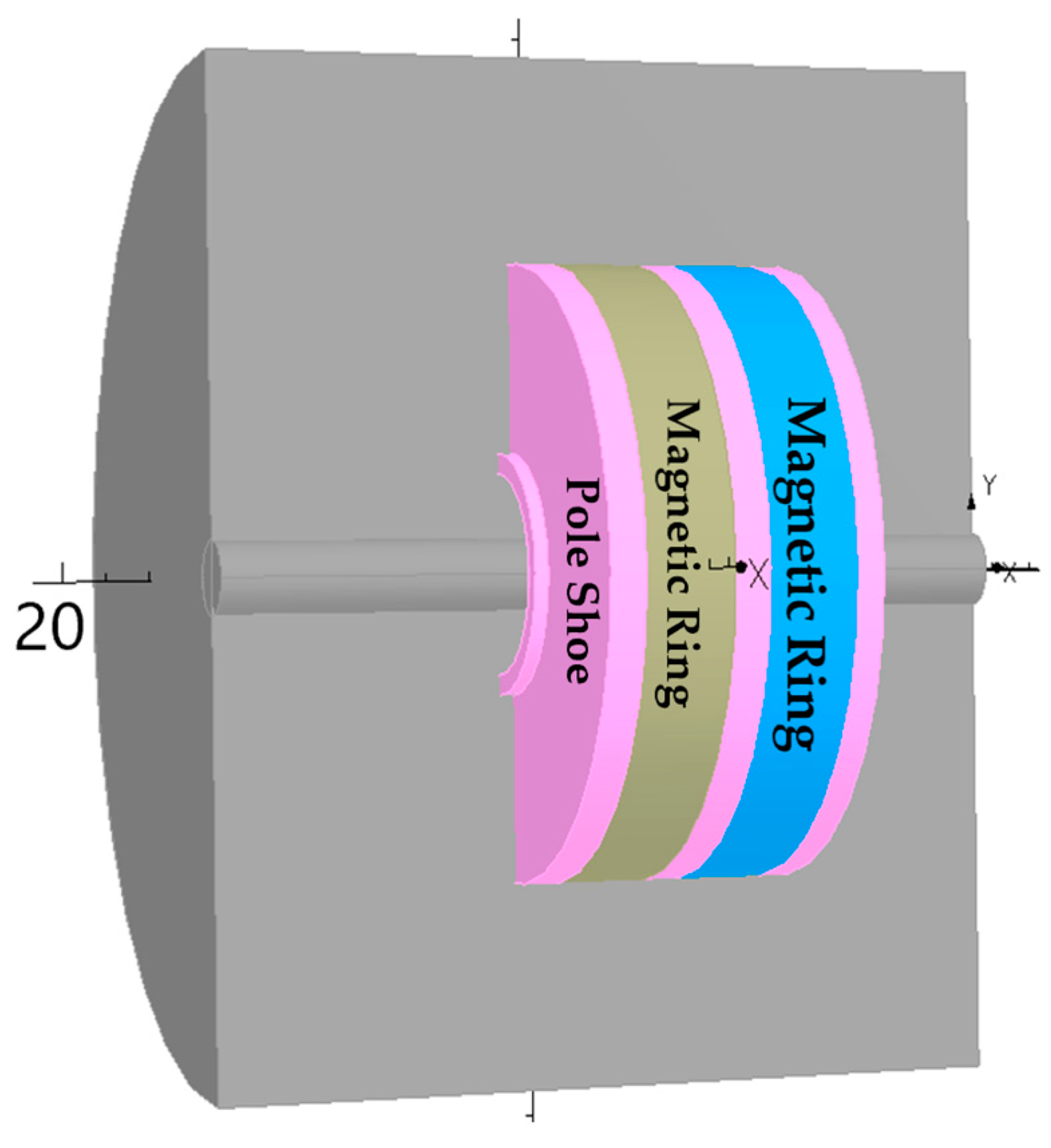
The electron beam emitted from the cathode passes through the focusing pole and the anode hole and continues on its way into the interaction region of the traveling wave tube. In the interaction region, the electron beam is only subjected to the space charge force. If there is no external force, the electron beam will diverge. In terahertz traveling wave tubes, a PPM-focusing system is usually used to constrain the electron beam to ensure that the electron beam is stable without divergence. The PPM system consists of a series of magnetic rings arranged with pole shoes separating the rings from each other. The magnetic rings are made of special samarium cobalt permanent magnets, and the pole shoes are composed of pure iron. Adjacent magnetic rings are polarized in opposite directions, resulting in a periodic magnetic field change in axial line, as shown in Figure 5.
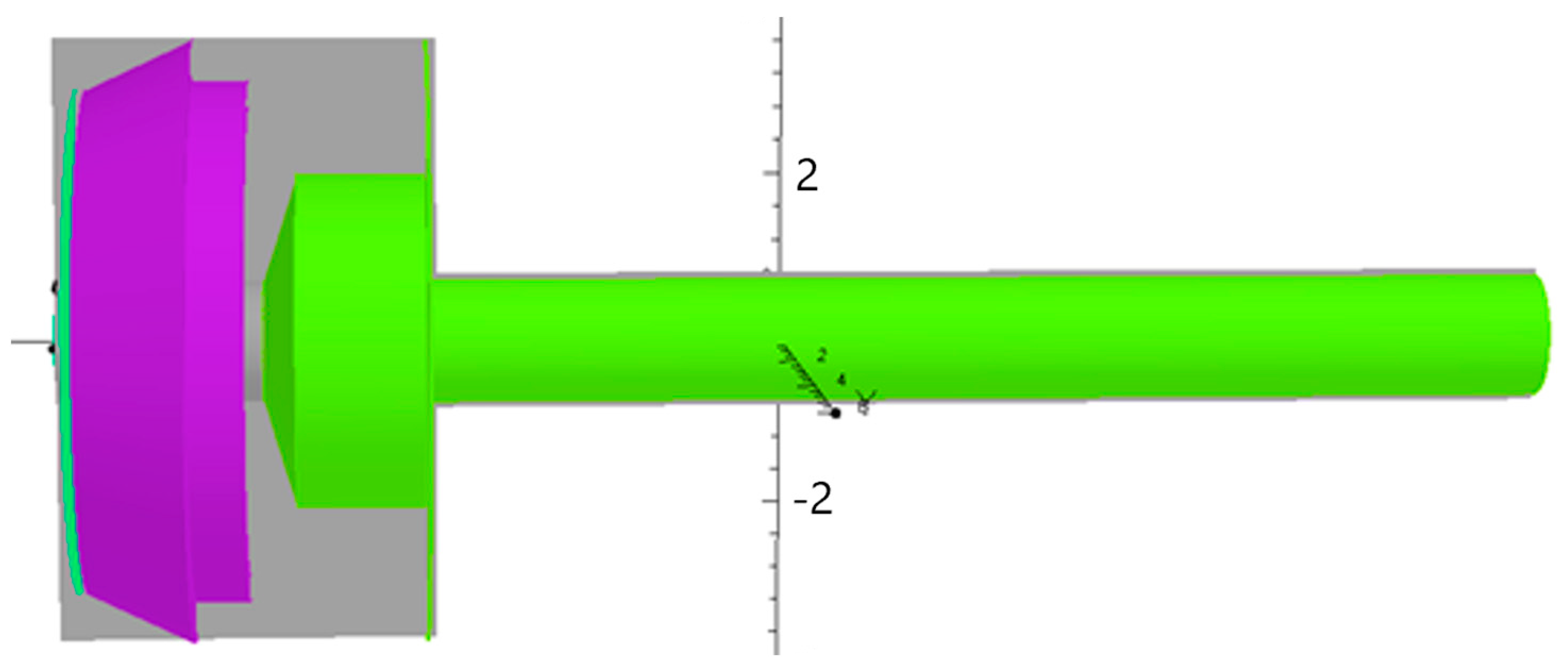
Figure 6 depicts the model of a PPM-focusing magnetic field period. The TOSCA module in Opera-3D was also used to calculate the static magnetic field, which can be used to calculate the current, electrostatic, and static magnetic fields including the impact of the three-dimensional nonlinear medium.

2.3. Design and Parameters

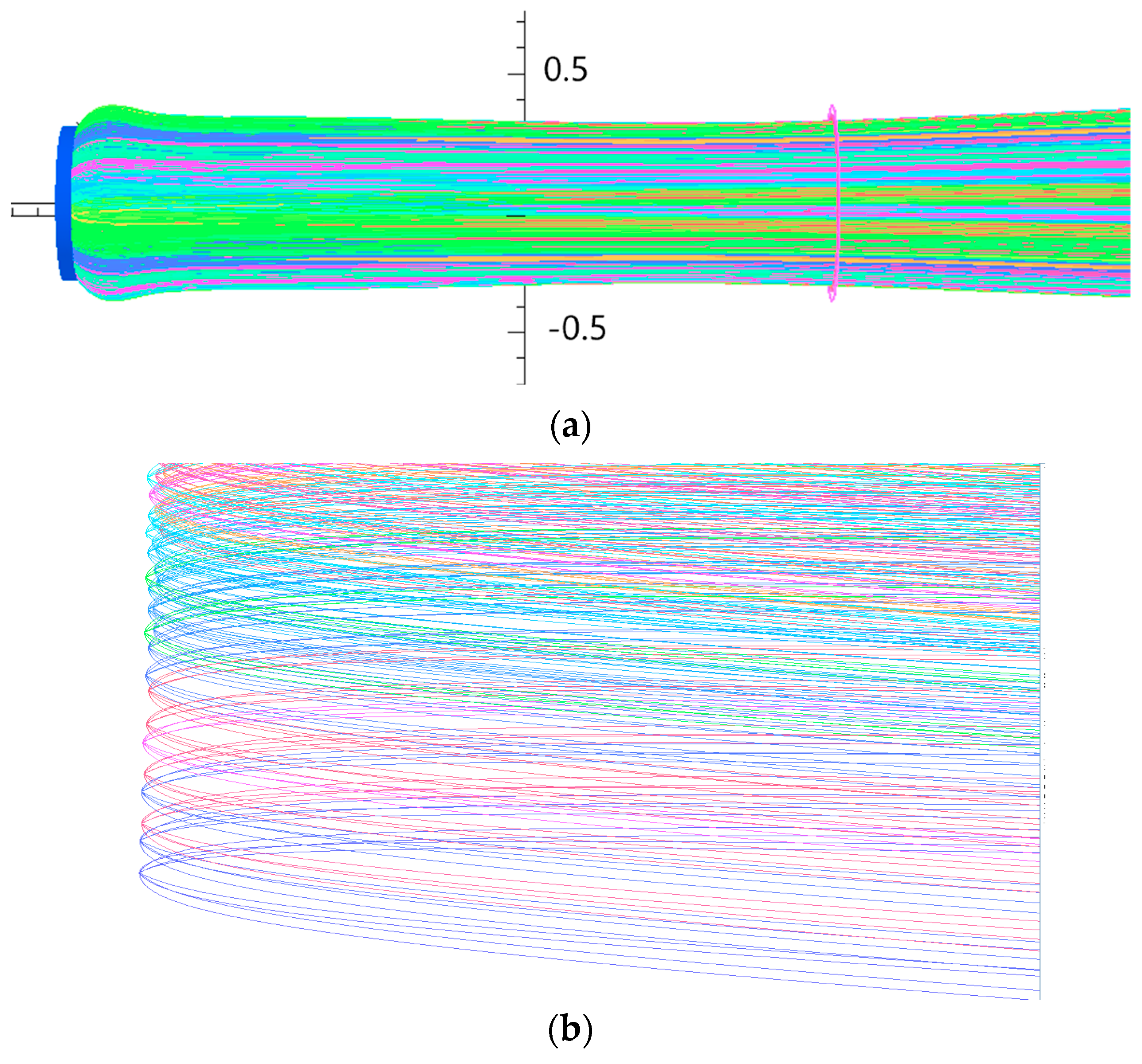
For the Spindt cold cathode electron gun design, the 3D electromagnetic analysis software Opera-3D was used to simulate the characteristics of the electron gun. Figure 7 displays a simulated electron gun model, consisting of a planar cold cathode, a focusing electrode, and an anode. The shape of the Spindt cold cathode was set as a plane. The position and the size of the focusing electrode and anode were initially determined via theoretical calculations and then optimized through simulations to achieve the well-focusing electron beam. The voltages of the emitters, the gate, the focusing electrode, and the anode were set to 0, 150, 200, and 5000 V. Figure 8a shows the plot of the electron beam trajectory in the electron gun region without the PPM magnetic field, with an operating current of 30 mA. As can be observed from Figure 8a, the focusing electrode achieved a good focus on the electron beam. Clearly, no trajectory crossover was detected, and the electron beam had good laminar flow. The distance from the beam waist to the cathode-emitting surface was about 3 mm. An enlarged view of the electron trajectory at each emitting point on the cathode-emitting surface is depicted in Figure 8b. Each emitting point is equivalent to an actual emitter, because the actual emitter is too small and numerous to be simulated with the electron gun. The cathode-emitting surface was meshed to generate 5000 grids in simulation, and each grid was defined as an emitting point. Thus, a total of 5000 emitting points were defined, i.e., 5000 emitting points instead of the actual 11,300 emitters. Of course, the cold cathode-emitting surface can be divided into more grids, i.e., define more emitting points, which depends on the conditions of the simulation calculation. In addition to the above, this new 3D emitting model can also simulate electron divergences of up to 28° at the emitting surface, which validate the fact that the simulations assume the actual electron trajectories, thus yielding better experimental results.
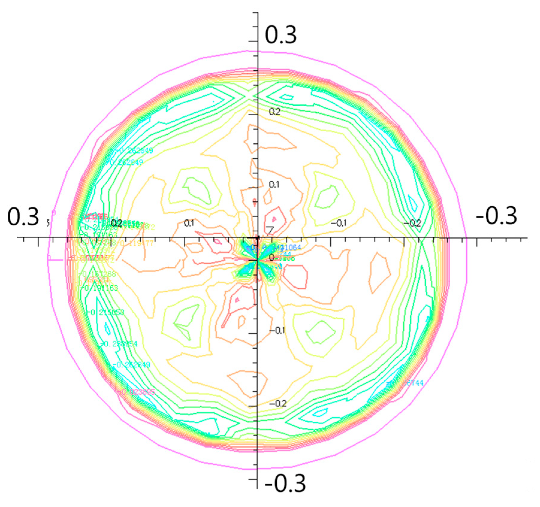
Figure 9 illustrates the distribution diagram of the equal charge density of the electron beam cross-section at the beam waist, i.e., Z = 3 mm. As seen in Figure 9, the beam radius was about 0.32 mm. Different colors indicated different current densities. The concentric circles in the outer layer indicated that the electron beam did not cross each other, exhibiting good beam laminarity. Since the anode was short and the current density was small, the space charge effect was not obvious and the electron beam was well focused in the electron gun region, which ensured that the electrons were incident into the interaction region of the electron gun with a small transverse velocity.
The model of a PPM-focusing system applied in the terahertz TWT is shown in Figure 10. As can be observed in Figure 10a, the peak value of the magnetic field was 0.16 T. Figure 10b depicts the vector distribution of the magnetic field for one PPM period.
The calculated magnetic field produced by the PPM period was applied to the interaction region of the terahertz TWT, and the electron beam under the action of the magnetic field is displayed in Figure 11. As can be seen from Figure 11a, the electron beam diverged in the interaction region, and the PPM-focusing system cannot focus easily on the electron beam. Varying the magnetic field on the central axis, the magnetic field peaking at 0.141 T and 0.122 T on the central axis were applied to the electron beam interaction region, respectively, resulting thus in the electron beam trajectories shown in Figure 11b,c. Compared with the electron beam shown in Figure 11a, the electron beam focusing in Figure 11b was effectively improved, but there was still a significant divergence at the interaction exit. When the axial magnetic field Bz was reduced to 0.122 T, the electron beam trajectories were even without divergence at the interaction exit. From the comparative analysis of the above results, it could be argued that when the peak Bz was 0.122 T, the electron injection advanced evenly behind the beam waist and the radius of the electron beam was about 0.3 mm. Figure 12 shows the equal charge density distribution of the electron beam cross-section at z = 15 mm. As can be seen in Figure 12, the outer electron laminarity was good and the inner electrons partially crossed.
It also can also be seen that by adjusting the PPM-focusing magnetic field, a good focusing of the electron beam with a waist radius of 0.3 mm can be achieved at a working current of 30 mA, and the electron beam filling ratio was 0.5. For the design of small and medium power terahertz TWT, the electron beam filling ratio r/a was selected between 0.5 and 0.75. Table 1 lists the operating parameters of the electron gun and calculated results.

3. Experimental Results

Based on the simulation described above, a planar cold cathode electron gun was developed, as shown in Figure 13, including the cathode, the focusing electrode, and the anode. The focusing electrode and anode were assembled together through hydrogen welding at 750 °C, and the FEA cathode was spot-welded to the component; however, the emitters of the cathode were easily damaged in the spot-welding process. To perform the measurements, the electron gun was connected to the measurement fixture in a vacuum chamber with a pressure of 1.4 × 10⁻⁶ Pa. A planar electrode was used as a collector to collect electrons emitted from the anode hole, which was set 5 mm in front of the gun. The voltages of the focusing electrode and the anode were set at 200 V (dc) and 5000 V (dc), respectively. The cathode emission current (mA) as a function of the gate voltage (V) was measured when the gate voltage was changed from 10 V to 140 V, as shown in Figure 14. In Figure 14, it can be seen that the I/V characteristics of the cold cathode gun were consistent with the cold cathode. Measurements reveal that the emission performance of the cold cathode was stable and that the electrons were not intercepted when passing through the electron gun, which is consistent with simulation results.

4. Conclusions and Perspectives

In this article, we studied a new 3D simulation of a cold cathode electron gun with electron divergences of up to 28° at the emitting surface. Based on the geometry of the Pierce electron gun, a planar cold cathode electron gun with a cathode surface of 0.6 mm and an operating current of 30 mA was designed and jointly simulated through the PPM magnetic system. The simulated results demonstrate that a good laminarity of the electron beam with a waist radius of 0.3 mm can be attained, whereas the electron–filling ratio was 0.5. A planar cold cathode electron gun was developed and measured in a vacuum chamber. The measurement results show that the cold cathode was in good working condition, and additionally, the electrons were not intercepted when passing through the electron gun, which is consistent with simulation results.

Author Contributions

Conceptualization, Y.L. and J.F.; methodology, J.F.; software, H.L.; investigation, Y.L. and H.L.; resources, Y.L.; writing—original draft preparation, H.L. All authors have read and agreed to the published version of the manuscript.

Funding

This research was funded by the National Natural Science Foundation of China, grant numbers 62041402 and 61474139.

Data Availability Statement

Not applicable.

Conflicts of Interest

The authors declare no conflict of interest.

References

  1. Srivastava, V. Novel current mode electronically tunable lossless integrator employing VDTA. In Proceedings of the 2015 Annual IEEE India Conference (INDICON), New Delhi, India, 17–20 December 2015; pp. 1–5. [Google Scholar]
  2. Beigang, R. The route from fundamental physics to real world applications. In Proceedings of the 2016 41st THz Technology International Conference on Infrared, Millimeter, and Terahertz waves (IRMMW-THz), Copenhagen, Denmark, 25–30 September 2016; p. 1. [Google Scholar]
  3. Han, S.-T.; Jeon, S.-G.; Shin, Y.-M.; Jang, K.-H.; So, J.-K.; Kim, J.-H.; Chang, S.-S.; Park, G.-S. Experimental investigations on miniaturized high-frequency vacuum electron devices. IEEE Trans. Plasma Sci. 2005, 33, 679–684. [Google Scholar]
  4. Spindt, C.A.; Brodie, I.; Humphrey, L.; Westerberg, E.R. Physical properties of thin-film field emission cathodes with molybdenum cones. J. Appl. Phys. 1976, 47, 5248–5263. [Google Scholar] [CrossRef]
  5. Charbonnier, F.M.; Barbour, J.P.; Garrett, L.F.; Dyke, W.P. Basic and applied studies of field emission at microwave frequencies. Proc. IEEE. 1963, 51, 991–1004. [Google Scholar] [CrossRef]
  6. Whaley, D.R.; Gannon, B.M.; Smith, C.R.; Armstrong, C.M.; Spindt, C.A. Application of Field Emitter Arrays to Microwave Power Amplifiers. IEEE Trans. Plasma Sci. 2002, 30, 998. [Google Scholar] [CrossRef]
  7. Yuan, X.; Wang, B.; Cole, M.T.; Zhang, Y.; Deng, S.; Milne, W.I.; Yan, Y. Theoretical Research on a Multibeam-Modulated Electron Gun Based on Carbon Nanotube Cold Cathodes. IEEE Trans. Electron Devices 2016, 63, 2919–2924. [Google Scholar] [CrossRef]
  8. Lin, C.M.; Chang, S.J.; Yokoyama, M.; Lin, I.N.; Chen, J.F.; Huang, B.R. Field-emission enhancement of Mo-tip field-emitted arrays fabricated by using a redox method. IEEE Electron Device Lett. 2000, 21, 560–562. [Google Scholar] [CrossRef]
  9. Schwoebel, P.R.; Spindt, C.A.; Holland, C.E. High current, high current density field emitter array cathodes. J. Vac. Sci. Technol. B 2005, 23, 691–693. [Google Scholar] [CrossRef]
  10. Makishima, H.; Miyano, S.; Imura, H.; Matsuoka, J.; Takemura, H.; Okamoto, A. Design and performance of traveling-wave tubes using field emitter array cathodes. Appl. Surf. Sci. 1999, 146, 230. [Google Scholar] [CrossRef]
  11. Li, X.; Bai, G.; Ding, M.; Zhang, F.; Feng, J.; Liao, F. Field Emitter Array Electron Gun for Traveling Wave Tubes. In Proceedings of the IVESC 2012, Monterey, CA, USA, 24–26 April 2012; p. 305. [Google Scholar]
  12. Fowler, R.H.; Nordheim, L. Electron emission in intense electric fields. Proc. R. Soc. Lond. 1928, 119, 173–181. [Google Scholar]
  13. Jensen, K.L.; Mukhopandhyay-Phillips, P.; Zaidman, E.G.; Nguyen, K.; Kodis, M.A.; Malsawma, L.; Hor, C. Electron emission from a single spindt-type field emitter: Comparison of theory with experiment. Appl. Surf. Sci. 1997, 111, 204. [Google Scholar] [CrossRef]
  14. van Veen, G.N.A. Collimated sputter deposition, A novel method for large area deposition of Spindt type field emission tips. J. Vac. Sci. Technol. B 1994, 12, 655. [Google Scholar] [CrossRef]
  15. Dvorson, L.; Ding, M.; Akinwande, A. Analytical electrostatic model of silicon conical field emitters I. IEEE Trans. Electron Devices 2001, 48, 134–143. [Google Scholar] [CrossRef]
  16. Dvorson, L.; Ding, M.; Akinwande, A.I. Analytical Electrostatic Model of Silicon Conical Field Emitters-Part II: Extension to Devices with Focusing Electrode. IEEE Trans. Electron Devices 2001, 48, 144–148. [Google Scholar] [CrossRef]
  17. Li, H.; Feng, J. Simulation Study of Field Emitter Arrays Using Opera-3D. In Proceedings of the 2008 IEEE International Vacuum Electronics Conference, Monterey, CA, USA, 22–24 April 2008; p. 351. [Google Scholar]
  18. Zhang, Y.; Liu, X.; Zhao, L.; Li, Y.; Li, Z. Simulation and Optimization of CNTs Cold Cathode Emission Grid Structure. Nanomaterials 2023, 13, 50. [Google Scholar] [CrossRef] [PubMed]
  19. Li, N.; Yan, F.; Pang, S.; Zeng, B.; Luo, Y. Novel Nanofabricated Mo Field-Emitter Array for Low-Cost and Large-Area Application. IEEE Trans. Electron Devices 2018, 65, 4369–4374. [Google Scholar] [CrossRef]
Figure 1. SEM (scanning electron microscope) image of a Spindt cold cathode consisting of Mo tips.
Electronics 12 04197 g001
Figure 2. Schematic representation of a Mo emitter, where θ   is the angle of the symmetry axis to the cone emitter.
Electronics 12 04197 g002
Figure 3. Variation of the electric field E ( θ ) with the emitting half angle θ .
Electronics 12 04197 g003
Figure 4. Schematic illustration of electron trajectories from Mo tips.
Electronics 12 04197 g004
Figure 5. The PPM system consists of a series of magnetic rings arranged with pole shoes separating the magnetic rings from each other.
Electronics 12 04197 g005
Figure 6. A model of a PPM-focusing magnetic field period.
Electronics 12 04197 g006
Figure 7. A model of the cold cathode electron gun consisting of a planar cold cathode, a gate, a focusing electrode, and an anode.
Electronics 12 04197 g007
Figure 8. (a) A 3D schematic of the beam trajectory from the planar cold cathode; (b) a 3D schematic of electron trajectories from emitting points with an emission half-angle of about 28°.
Electronics 12 04197 g008
Figure 9. Distribution diagram of the equal charge density of the electron beam cross-section at the beam waist.
Electronics 12 04197 g009
Figure 10. (a) Distribution of the magnetic field Bz profile on the central axis with the peak value of 0.16 T; (b) the vector distribution of the magnetic field for one PPM period.
Electronics 12 04197 g010
Figure 11. Depiction of the electron beam under the action of the magnetic field with the peak value of (a) 0.16 T, (b) 0.141 T, and (c) 0.122 T.
Electronics 12 04197 g011
Figure 12. Distribution diagram of the equal charge density of the electron beam cross-section at the beam waist.
Electronics 12 04197 g012
Figure 13. Optical photograph of the cold cathode electron gun, including the cathode, focusing electrode and anode.
Electronics 12 04197 g013
Figure 14. Electron emission characteristics of the cold electron gun.
Electronics 12 04197 g014
Table 1. The operating parameters of the electron gun.
ParameterValue
Operating current30 mA
Gate voltage150 V
Focusing electrode voltage200 V
Anode voltage5000 V
Peak value of the PPM magnetic field0.122 T
Waist radius0.3 mm
Electron beam filling ratio0.5
Disclaimer/Publisher’s Note: The statements, opinions and data contained in all publications are solely those of the individual author(s) and contributor(s) and not of MDPI and/or the editor(s). MDPI and/or the editor(s) disclaim responsibility for any injury to people or property resulting from any ideas, methods, instructions or products referred to in the content.