Abstract
Coverage limitation due to signal attenuation is one of the main challenges facing single-hop LoRaWAN when deployed in IoT applications that require low power consumption and operate over a wide area network. The challenge can be figured out using the dense deployment of typical LoRaWAN gateways to ensure devices can transfer their data to the network server successfully. However, this is considered a costly path because of the requirement of deploying a larger number of gateways. To cope with this, a multi-hop communication strategy can be utilized to extend the coverage of employed LoRaWAN networks, eliminating the need for dense gateway deployment. Thus, this paper proposes a Listen-To-Talk-based Multi-hop LoRaWAN LTM-LoRaWAN, a multi-hop relaying system for a wide area LoRaWAN network. It supports out-of-range devices to deliver their traffic to the gateway without using complex routing mechanisms or routing topology construction. Moreover, the proposed system is dynamic and does not require any special entities or assign specific tasks to specific devices. The paper provides a detailed description of the design and configuration of the proposed LTM-LoRaWAN. Using simulation, the feasibility of the proposed system was demonstrated. The evaluation result showed that the proposed system outperformed one-hop LoRaWAN and achieved better reliability in traffic delivery.
1. Introduction
The LoRa has gained much attention recently, from both academic and industrial fields, due to its capability to facilitate efficient Device-to-Device (D2D) communications and provide applications for different areas, including smart cities, health care, smart agriculture, smart metering, and so forth [1,2]. LoRa operates using the unlicensed ISM sub-GHz band and uses Chirp Spread Spectrum and Frequency Shift Keying modulation that makes it more robust to interference while transmitting to longer distances. It supports low power consumption and long-range transmission reaching up to several kilometers range. However, the long coverage, along with minimum transmission power, comes at the cost of a low data rate [3].
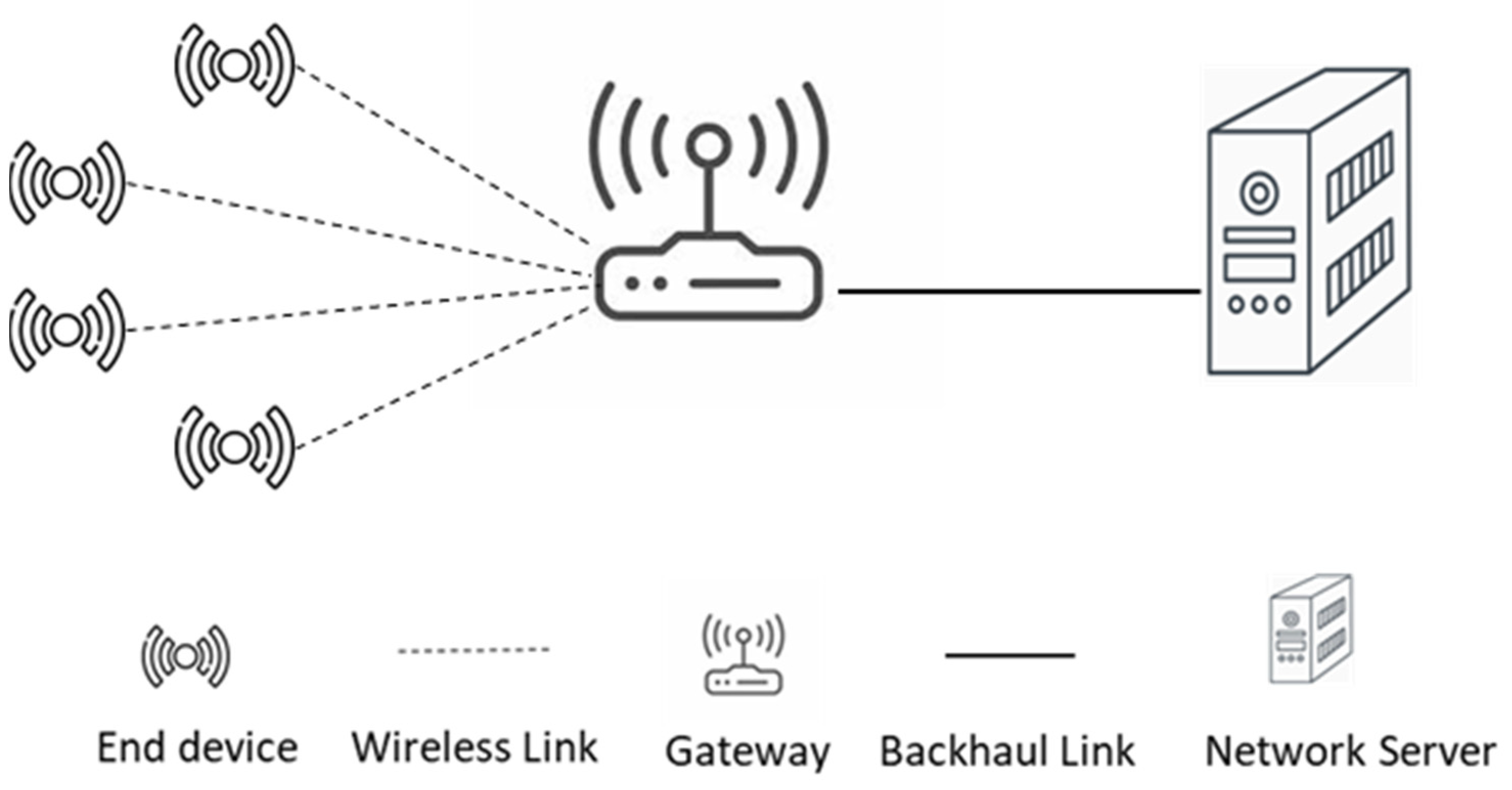
Long Range Wide Area Network (LoRaWAN) forms a star-of-star topology that contains end devices transmitting traffic to a gateway in a single-hop communication approach. Its basic design consists of end devices, gateways, and network servers, as shown in Figure 1. End devices are in charge of collecting data by interacting with the surrounding environments based on the purpose of the deployed application. The collected data are transmitted by end devices to one or more gateways using Spreading Factors ranging from 7–12. Gateways take the responsibility of forwarding the received traffic to the network server. Gateways are connected to the network server via an IP network. The network architecture implies that an end device must be in the radio range of the gateway to transmit its traffic successfully. However, the radio range can be reduced due to different possible obstacles in the deployed environment, such as buildings, Trees, and mountains, hence affecting the overall efficiency of the network. In addition to that, some deployment scenarios require much longer coverage based on the purpose of the employed applications. Being out of the gateway range can also be a result of mobility if the end devices are mobile [4]. Therefore, multi-hop LoRaWAN can fill in this gap, allowing out-of-the-range devices to transmit their traffic to the gateway utilizing other end devices that are in the range of the gateway without installing additional gateway devices. The use of additional gateways is considered impractical sometimes since a gateway requires main power that would be difficult to supply in some remote locations. Moreover, employing multi-hop LoRaWAN would be justified for avoiding collisions since faraway devices can use a smaller Spreading Factor (SF). The use of lower SF reduces the Time-on-Air (TOA) a packet requires to travel to its destination. Thus decreasing the chance of collisions.
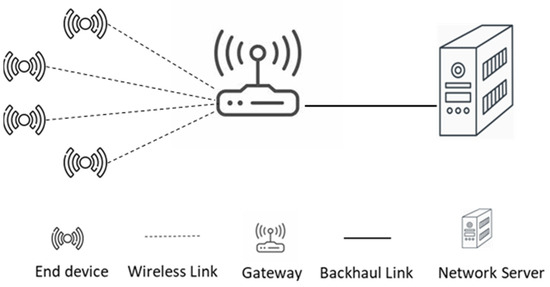
Figure 1.
Standard LoRaWAN Network.
LoRaWAN provides support for three different Medium Access Control (MAC) modes to satisfy different application requirements. An end device should operate according to one of the three classes: class A, class B, or class C [5]. Class A functions based on the application need. It offers bidirectional communication between the device and the gateway based on the ALOHA protocol. The communication starts with an uplink transmission, which is followed by two receive windows that can be used for downlink communication. It is considered the lowest power device mode. Class B, on the other hand, adopts synchronization of end devices with the network server to enable more receive windows in addition to the two receive windows of class A. A time synchronization beacon is sent periodically by a gateway to allow end devices to synchronize their clocks and, hence, entitle the network server to know the moment that an end device is awake. It targets reducing the delay for the network server to transmit downlink data to an end device. Class C, finally, provides the least latency for downlink traffic since it opens an almost continuous receive window. The receive window is closed only when the device is transmitting. However, class C-enabled devices consume more power compared to classes A and B.
LoRaWAN employs an Adaptive Data Rate (ADR) mechanism as a method to adjust and control some of the network configuration parameters to reach an optimal operation [6]. ADR’s main motivation is to efficiently set the data rate, which consequently affects network capacity and power consumption [7]. It operates on two sides: the network server and the end devices. The one at the end device side is designed to entitle an end device to increase its transmission range via increasing transmission power and spreading factor. The end device maintains a counter to figure out whether it has received any ADR command or downlink messages from the server. If the counter reaches a threshold, the transmission power and spreading factor are accordingly increased. On the other hand, the network server ADR works on demand as requested by an end device. The network server measures the link budget between itself and an end device based on the last 20 packets exchanged. The collected information is used by the network server to first decrease the spreading factor and then adjust the transmission power. The recommendation is finally sent to the end device.
Several works have been proposed in the literature to handle the deployment of multi-hop LoRaWAN. Most of the proposed works are dependent on some assumptions which make their solutions appropriate for special cases. An example of that is the assumption of the use of synchronization where end devices and gateway are synchronized. Such synchronization would enable communicating devices to control activity time. This, however, contradicts the typical MAC approach used by LoRaWAN, ALOHA protocol. Other solutions assume the prior knowledge of the network topology to allow the use of some specific network construction technique, such as building a tree topology.
This paper proposes Listen-To-Talk-based Multi-hop LoRaWAN (LTM-LoRaWAN) to support multi-hop communication in LoRaWAN. The proposed system first entitles an end device to determine whether or not the device is in the range of a gateway by optimizing the existing ADR mechanism. The proposed system then provides a lightweight procedure for transmitting and forwarding out-of-range device traffic to a gateway. This requires the proposed system to employ a different mechanism for medium access similar to Listen-before-Talk. The contribution of this paper is the detailed design of LTM-LoRaWAN and a comprehensive simulative evaluation of the proposed system. Moreover, the paper provides a comparative assessment of the proposed multi-hop system compared to one-hop LoRaWAN using several performance metrics.
The remainder of this paper has been organized as follows. Section 2 introduces the existing related work in the literature. The proposed system is then presented in Section 3. The evaluation of the proposed system is addressed in Section 4. The section begins by introducing the network model and the configuration parameters. It then defines the evaluation metric and introduces and discusses the result of the evaluation. The conclusion is finally drawn in Section 5.
2. Related Works
LoRaWAN multi-hop communication approach has been investigated by several publications in the literature to find out its feasibility in increasing network coverage. It has been used in several LoRaWAN IoT applications, such as environmental monitoring [8], underground monitoring [9], oil pipeline detection [10], and smart cities [11]. This part of the paper covers current research related more to the relaying approaches rather than the routing. A comprehensive survey for multi-hop communication in the LoRaWAN field can be found in [3,12,13].
The work in [14] used a special node (Enhanced Node) to extend the range of the transmitted traffic. The Enhanced node requires a continuous power supply to stay ready for any incoming traffic. It operates at the link layer level. The Enhanced node duty is to replicate any received messages without enforcing any limitation if the incoming traffic does not require confirmation. However, the subsequent receive windows are used for confirmed traffic along with synchronizing the incoming and sending paths. In the case of downlink traffic, a gateway is required to transmit the downlink traffic after the first receive window of the e-node, whereas the e-node is required to send the downlink after the end of the second receive window of the initial uplink message. The feasibility of the e-node proposal was tested in 2800 industrial laboratory. The e-node was located about 100 m away from the gateway, and few nodes transmitting traffic were used.
The work in [15] suggested the addition of a relay device after the deployment of the network. The relay devices are placed in locations to serve far away LoRaWAN end devices and work as intermediate entities, relaying the traffic toward the gateway. The proposed relay nodes are different from standard end devices, where their main task is to extend the coverage of the LoRaWAN network via receiving and forwarding operations. One of the proposal’s main considerations was to select the most appropriate location for the relay device. The relay devices can switch between active and sleep mode based on the analysis of the uplink traffic pattern. In addition, they are proposed as transparent where the end devices and the gateways are not aware of the existence of such relay devices. The proposed approach assumed two phases for a relay device operation. The first is when the relay device stays in active mode to discover end nodes within its vicinity and observe uplink traffic. Once a relay device finishes its observation phase, it moves to the second phase, the data forwarding stage. In this stage, the relay device is in sleep mode and wakes up periodically to receive and forward uplink traffic.
On-demand forwarding has been used in [16], where relay nodes forward the received packet if and only if the network server does not receive it. This was achieved using an on-demand feedback mechanism by the server to inform the relay nodes of the status of a particular packet. The proposal made use of priority-based forwarding as well. The priority is organized based on the RSSI, which is distributed by the network server in advance of transmitting the feedback message. The relaying node with the highest priority can forward a packet immediately when it receives a feedback message from the server. Other relaying nodes should stay in active mode all the time, listening to the transmission from the relaying node with higher priority. Once the relay with higher priority is finished, the other can start forwarding their messages. The proposal was evaluated in simulation and achieved a similar delivery ratio with a smaller number of retransmissions.
The work in [11] proposed two architectures to serve multiple hops in LoRaWAN. The first architecture assumes that an end device can operate as a relay node to forward faraway node traffic toward a gateway. However, the paper lacks a description of how the forwarding mechanism works. It claimed that the relay node operates a decode and forward mechanism. Moreover, the work evaluated the proposal using real experiments with a few devices that were placed only a few hundred meters from each other. The second architecture divides the network topology into several clusters. Each cluster has its gateway, which forwards the traffic towards a main gateway. The architecture was evaluated in a 290 m × 210 m topology covering two clusters.
An opportunistic protocol for LoRa, named LoRaOpp, was proposed in [17]. It uses some opportunistic mechanisms, such as source routing and spray and focus, which have been studied to handle disruption and opportunistic networking in the literature. These mechanisms were used to limit the number of forwarded packets in the network. The proposal assumes three different LoRa devices: end node, peer node, and gateways. It assumed that LoRa devices are capable of storing data in case the next node in the path is not reachable until the following contact opportunity. LoRaOpp used broadcasting to allow gateways and end devices to announce their existence via broadcasting dedicated packets frequently. The protocol uses a collision detection mechanism and retransmission technique to avoid data loss. It was evaluated experimentally in an outdoor environment with seven end devices, including the gateway. An emulation was also used to evaluate the performance of the proposal in larger networks that contain up to 100 LoRa devices.
Based on the LoRa physical layer, the work in [18] proposed a mesh LoRaWAN named LoRaMesh aiming to extend the coverage of LoRaWAN networks. To implement multi-hop functionality, the proposed system modified several components of LoRaWAN, including the implementation of the network server, reception windows, and packet headers to facilitate retransmission. Bacon flooding is initiated by Gateways and is used to keep time synchronization among devices. The synchronization bacon is then retransmitted by one hop device to other LoRaWAN devices. A rule-based mechanism is used to set a fixed transmission schedule for every single device at the beginning of the network, where each child device is assigned a slot time for transmission. The proposal assumes a routing procedure with a global knowledge of locations and path loss between devices and the gateway to calculate routing paths and build tree structure routing for the whole network. The network server determines parent devices as well as children’s devices. The proposal was implemented in NS-3, evaluated, and compared to single-hop LoRaWAN.
A genetic algorithm was used in [19] to optimize the performance of the LoRaWAN network in terms of latency and coverage probability. The study investigated the performance of dual-hop LoRaWAN following the cooperative communication strategy where devices cooperate to carry out data transmission. The study then utilized a genetic algorithm to obtain the LoRa device’s optimal transmission configuration in terms of received power, where it is at its maximum value. The achieved values are then utilized to enhance the performance regarding coverage and latency. The proposal was simulated in MATLAB, and it is reported that it improved the coverage of the network by about 20%.
A two-hop real-time LoRa was proposed in [20] and extended in [21]. The proposed protocol contains two main phases: tree topology construction and slot scheduling. In the first phase, the protocol constructs a tree topology of the network based on the quality of the links between end devices and the gateway. The tree topology is then used by the network server to perform slot scheduling between one-hop and two-hop neighbors of the gateways. The one-hop end devices can transmit their uplink traffic directly, and the two-hop devices use one of the one-hop devices as a relaying node to transmit their traffic on the scheduled slots. The proposal optimizes broadcasting to build the tree topology where a gateway is required to broadcast a Tree Construction Request that will be received by all possible one-hop devices. The Tree Construction Request is then re-broadcast to other possible two-hop devices. Two-hop devices evaluate the received Tree Construction Requests to decide their parents. All end devices are required to transmit traffic periodically to maintain the topology. The proposal was evaluated in a testbed containing one gateway and ten nodes, which were located manually to have two-hop nodes in the topology.
The work in [22,23] proposed a multi-hop communication protocol based on a centralized MAC LoRaWAN instead of the MAC mechanisms used by standard LoRaWAN, such as Listen Before Talk and ALOHA. It uses Time Division Multiple Access (TDMA) as the medium access strategy to target real-time IoT applications. The main goal of the proposed system was to decrease the Time on Air (ToA) by utilizing a multi-hop technique to allow the LoRa device to use a smaller spreading factor. The proposed solution adopted a hierarchical topology approach. The end devices are organized in advance of the network operation; hence, the network topology is assumed to be priorly known. The whole topology is divided into several layers, where the first layer constitutes devices with one hop distance from the network gateway. Relaying of messages is restricted to devices that belong to adjacent layers. The system assumes the usage of devices that exclusively work as relay devices. It also uses frequent Bacon broadcasting to maintain node synchronization in the network. The proposed system was evaluated in a simulation environment using OMNeT++ with three layers of tree topology containing up to 54 nodes.
3. Proposed Protocol Design
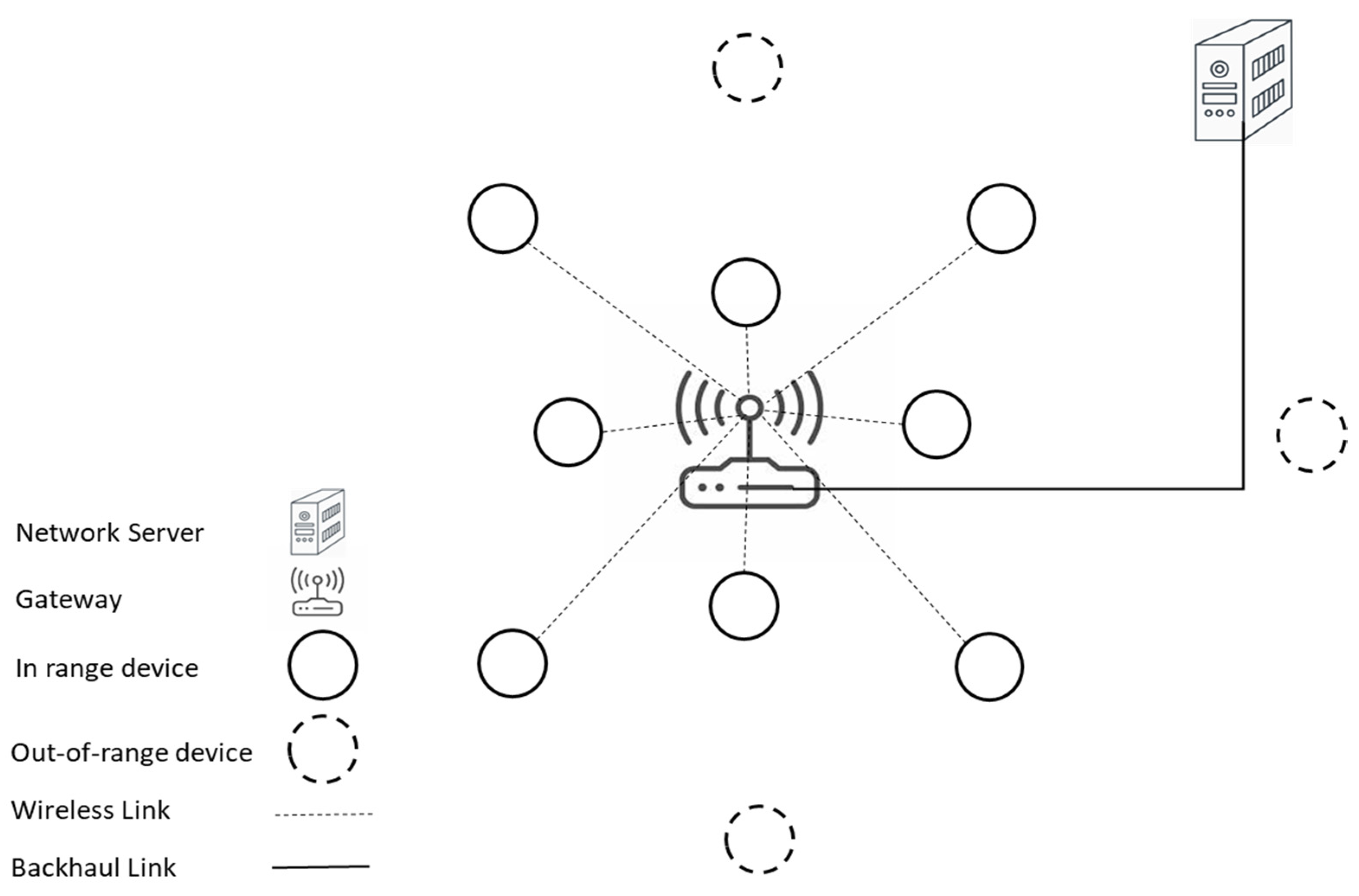
This paper proposes a novel lightweight mechanism based on LoRaWAN to enable multi-hop communication named Listen-to-Talk-based Multi-hop LoRaWAN (LTM-LoRaWAN). The main goal is to allow out-of-range devices to deliver their traffic to the gateway while keeping the typical LoRaWAN functionalities as simple as possible. This is achieved by utilizing other in-range devices to forward the messages toward the gateway. The proposed system avoids any use of complex routing mechanisms or routing topology construction, nor does it use special entities or assign specific tasks to specific devices. This is to keep the functionality of the proposed one as similar as possible to standard LoRaWAN. The network model under investigation contains a network server, a gateway, and hundreds of LoRaWAN devices. No specific rules or functionalities are assigned to any device before the network deployment. All the end devices are standard devices. However, the proposed system entitles the devices to opt for forwarding their traffic based on their needs. Moreover, the proposed system introduces a lightweight mechanism within the end device’s functionalities to allow them to participate in traffic forwarding. Figure 2 displays a simple representation of the considered LoRaWAN network containing out-of-range end devices in addition to standard LoRaWAN end devices.
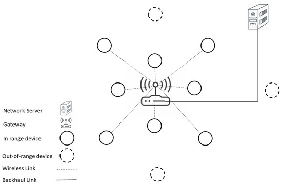
Figure 2.
Network Topology.
The proposed protocol involves two main phases to carry out delivering faraway device traffic to the gateway. The first phase is related to out-of-range LoRaWAN devices. It covers the process according to which a device can identify itself as being out of the range of the gateway. The second phase is related to the process of transmitting and forwarding out-of-coverage devices’ traffic. The latter phase contains the proposed strategies that are embedded in the procedure of both out-of-range devices and other in-range devices.
3.1. Identification of Being out of a Gateway Coverage
The first phase in the proposed system is concerned with a device identifying itself as out of the gateway coverage. Therefore, delivering its messages requires collaboration from other LoRaWAN devices to pass on its messages to the gateway. The standard LoRaWAN offers an Adaptive Date Rate (ADR) to allow devices to control their data rate and, hence, increase the network efficiency. ADR operates on two different sides: the network server side and the end devices side. The ADR feature at the LoRaWAN device side is optimized and modified by the proposed system to serve for identifying out-of-range devices. ADR employs a counter to maintain connectivity with the gateway. The counter is increased for each transmission and reset to zero value if the device receives an ADR command or a downlink message. In the case that the counter reaches a predefined limit, the device must regain connectivity by increasing its transmission power and spreading factor, which allows longer radio coverage with a lower data rate. This feature has been modified and utilized by the proposed system to identify being out of the radio range of the gateway [24].
When the spreading factor has been increased to its maximum value, 12, with no ADR command from the network server being received nor a downlink message for a predefined limit, it indicates that the end device is out of the gateway coverage even though it is using the maximum available SF and transmission power. The limit is defined by standard LoRaWAN as the sum of the number of acknowledgment limits and the number of acknowledgment delays. Once an end device reaches this point, it is regarded by the proposed system as an out-of-range end device, and its ADR mechanism is disabled. The proposed system then forces the current device to switch to the proposed mechanism LTM-LoRaWAN to be able to transmit its traffic despite being out of the coverage of the gateway. Algorithm 1 shows the pseudocode for identifying out-of-coverage LoRaWAN devices.
| Algorithm 1: Pseudocode for Identifying Out-of-Range Device | |
| 1: | PKT: End device Packet for transmission |
| 2: | ADR_ACK_CNT: ADR Acknowledgement Counter |
| 3: | ADR_ACK_LMT: ADR Acknowledgement Limit |
| 4: | ADR_ACK_DLY: ADR Acknowledgement Delay |
| 5: | SF: Spreading Factor |
| 6: | For each PKT do |
| 7: | increase ADR_ACK_CNT |
| 8: | If ADR_ACK_CNT >=(ADR_ACK_LMT + ADR_ACK_DLY) & SF = 12 & Transmission power is maximum |
| 9: | set forwarding field to 1 |
| 10: | set Time_To_Live to 1 |
| 11: | initialize ADR_ACK_CNT to zero |
| 12: | End if |
| 13: | End for |
3.2. Frame Structure
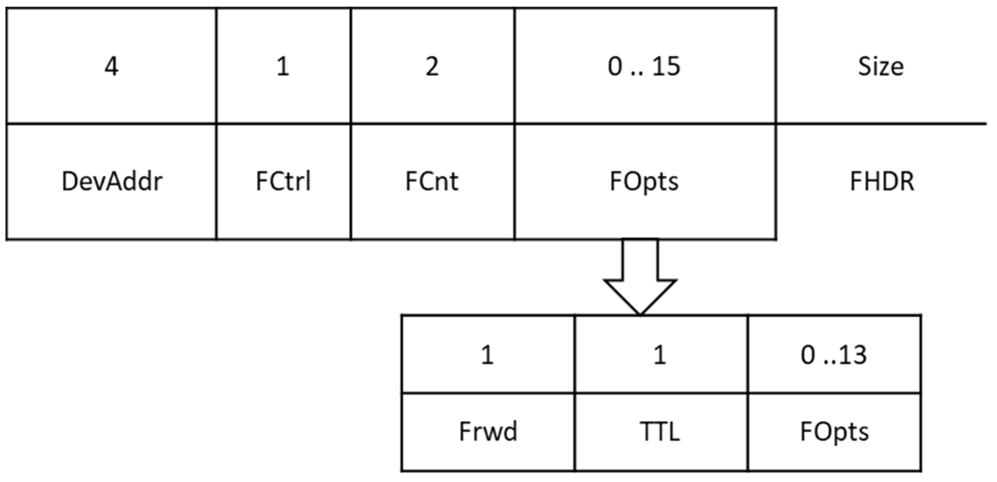
The uplink message format is re-engineered in the proposed system to contain the need for forwarding a message being transmitted by an end device. A MAC payload for a LoRaWAN frame consists of three parts: Frame Header (FHDR), Frame Port (FPORT), and Frame Payload (FRMPAYLOAD). The frame Header itself is divided into four sections with a size not exceeding 22 bytes, as shown in Figure 3. The frame option (FOpts) part is up to 15 bytes field and is used for MAC commands. A portion of the FOpts is used in the proposed system to hold the status of a transmitted message regarding the need for forwarding by other end devices in the network. Figure 3 shows the new format as well as the LoRaWAN frame header.

Figure 3.
Proposed Frame Header Structure.
Moreover, an end device in the proposed system is required to attach a Time-To-Live (TTL) value to its messages. The TTL is positioned next to the Forwarding status field in the new structure of the frame header. The TTL is assigned 1 in messages generated by an out-of-range device and 0 in messages issued by end devices that reside within the coverage of the gateway. This is used to control the broadcasting of out-of-range devices’ traffic and provide loop avoidance. The TTL is decreased to 0 once the message is forwarded by one or more of the neighbors of the out-of-the-range device. Therefore, the message no longer gets forwarded in case it has been received by other end devices, hence decreasing the chance of storming the network with the introduced forwarding mechanism and providing loop avoidance.
3.3. MAC Mechanism to Facilitate Transmission and Forwarding
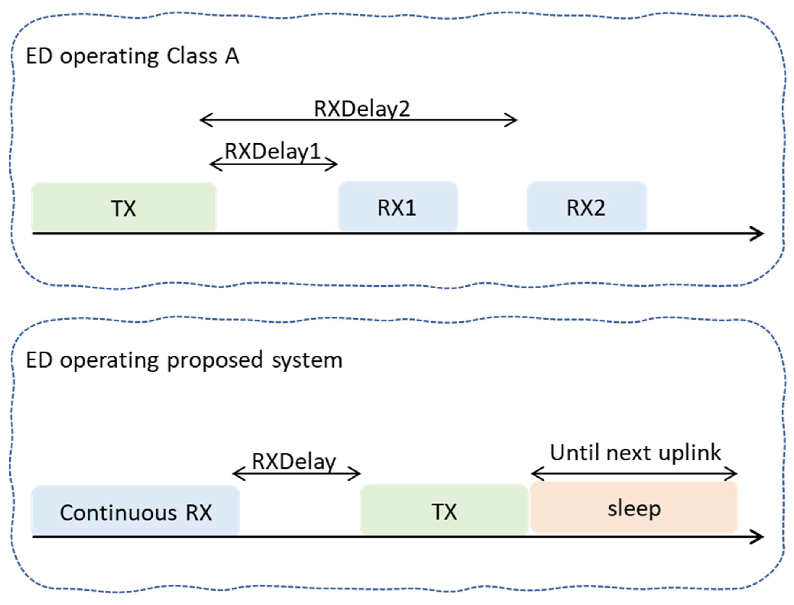
End devices in the proposed system implement the class A approach, which is the most implemented class, consumes the least amount of power compared to other classes, and provides the least functionalities of the LoRaWAN network. Similar to other classes, class A uses ALOHA as the medium access algorithm. An uplink transmission by an end device is followed by two short receive windows named RX1 and RX2. However, the proposed system opts for optimizing the ALOHA protocol by out-of-range devices to allow them to deliver their traffic to the main network server. Thus extending the coverage of the LoRaWAN network using a multi-hop strategy. Once an end device finds itself out of the range of the gateway based on phase one, it immediately employs a different scheme for medium access similar to Listen-Before-Talk (LBT) named Listen-To-Talk (LTT).
Differently from the traditional access scheme employed using the standard end device, the proposed medium access scheme forbids out-of-range devices to directly transmit their messages whenever they need to. Instead, the proposed system requires an out-of-range device to employ the Listen-To-Talk scheme. According to the utilized LTT, an out-of-range device starts the lifecycle of transmission by listening to other neighboring devices in advance of transmitting its traffic. Once the device senses an uplink transmission, the Listening phase of the LTT mechanism is finished. The listened uplink transmission indicates that there would be two receive windows following the transmission. This is possible since end devices use broadcasting when transmitting their messages toward LoRaWAN gateways, and hence, such transmission by closer-to-the-edge devices can be sensed by out-of-range devices. Thus, the proposed system utilizes these two windows to coincide out-of-range device transmission with one of the aforementioned two receive windows. In other words, the two receive windows of standard end devices are utilized by out-of-range devices to initiate their uplink communication. This constitutes the Talk phase of the employed LTT by the out-of-range device. Figure 4 shows the standard MAC operations for in-range and the LTT operation for out-of-range devices. After sensing and receiving a transmission, an out-of-range device delays its transmission for a while, then starts the transmission, hoping that such uplink traffic would coincide with one of the two receive windows. Once the transmission finishes, the end device sleeps until the next transmission is needed. The process of transmitting an uplink message for an end device in the proposed system is illustrated in Figure 5.
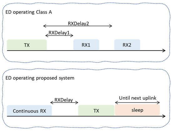
Figure 4.
MAC operation timing for the proposed system.
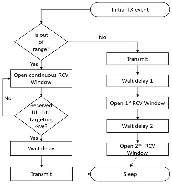
Figure 5.
Transmission of an uplink message diagram.
The second part of the second phase is the forwarding procedure that must be accomplished using other LoRaWAN end devices that have just received the message from an out-of-range device. The forwarding end device is expected to receive the message for forwarding during one of its two receive windows. Upon receiving and recognizing the message as a message for forwarding, the forwarding device cancels the other receiving window if it was in the first, sets its transmission parameters, such as SF and transmission power, to the received frame, and starts the transmission. It should be noted that the forwarding end device does not open any other receive windows and should go to sleep mode after the forwarding procedure. The pseudocode for the forwarding procedure is shown in Algorithm 2.
| Algorithm 2: Pseudocode for the Forwarding Procedure | |
| 1: | PKT: End device Packet for transmission |
| 2: | SF: Spreading Factor |
| 3: | TP: Transmission Power |
| 4: | TTL: Time-To-Live |
| 5: | RCVW: Receive Window |
| 6: | For each received PKT do |
| 7: | If (PKT for forwarding & I can see the gateway) |
| 8: | decrease PKT’s TTL |
| 9: | set SF & TP |
| 10: | cancel other RCVW if any |
| 11: | insert PKT into Transmission Queue |
| 12: | schedule PKT for transmission |
| 13: | End if |
| 14: | End for |
4. Performance Evaluation
This section presents the evaluation of the proposed system. Firstly, the system model and the used simulation configuration parameters are detailed. The evaluation metrics are then introduced, and the third subsection presents and discusses the evaluation result for the proposed system and the baseline.
4.1. System Model and Configuration Parameters
The simulation model in this study is based on the Framework for LoRa (FloRa) simulation model [25], which can be found at [26]. FloRa itself is developed based on the OMNeT++ network simulator and uses the INET framework. The simulation model has been modified to support the proposed system. It supports all the functionalities of the proposed system, which has been introduced in the previous section, including the identification of being out-of-range of a gateway, the procedure of medium access, and the forwarding mechanism.
The log-distance propagation model is the used model for path loss and propagation. It provides an estimation for an urban environment. It calculates path loss according to the following equation.
The is a path loss value for path loss calculation at 0 distance. The parameter shows the effect of the range on the data rate. The is a Gaussian random variable with zero-mean and presents standard deviation. The used path loss model uses 1000 m for , 128.95 dB for , 2.32 for , and 0 dB . The values were derived from real experiments in [27].
End devices are deployed in a 20 km × 20 km square area. For each simulated experiment, about 20% of the participating LoRa end devices were distributed close to the border of the area to allow the evaluation of the proposed system. The number of end devices varied from 100 to 1000 devices in the step of 100 end devices. One gateway was used and located in the middle of the simulation area. The characteristic of the SX1272 Lora device is used to give the simulator more realistic parameters, as it is an industry standard developed by Semtech [28]. The ADR mechanism is enabled for all the end devices and the network server as well. Hence, SF and transmission power are adopted using the ADR mechanism whenever it is needed based on the position and the circumstance for each single device. Each end device wakes up periodically to generate traffic with 30-byte sizes based on the used send interval. Two intervals were used, sixty minutes and ninety minutes. Every single experiment was repeated 10 times with a duration of 10 days. The performance of the proposed system was compared to the baseline, a LoRaWAN network operating one-hop communication in similar simulation configurations and parameters. Table 1 highlights the parameters used in the carried-out simulations.

Table 1.
Simulation Parameters.
4.2. Evaluation Metrics
- Delivery Ratio: it is the ratio of successfully received packets using the network server to the overall sent packets by all participating devices over the whole simulation time. The metric is evaluated according to the following equation.
- Total received packets by network server from out-of-range devices using the proposed mechanism compared to the total sent uplink traffic from the same devices.
- Amount of received packets by the main gateway’ LoRa receiver that is below the sensitivity of the gateway itself. The receiver sensitivity expresses the capability of the gateway radio receiver to extract the transmitted signal and, hence, indicates the weakness of the signal. The metric indicates the ability of the proposed system to decrease the overall lost traffic due to arriving below the sensitivity of the gateway.
- Average power consumption by an end device per day. It is calculated according to the following equation.
4.3. Result and Discussion
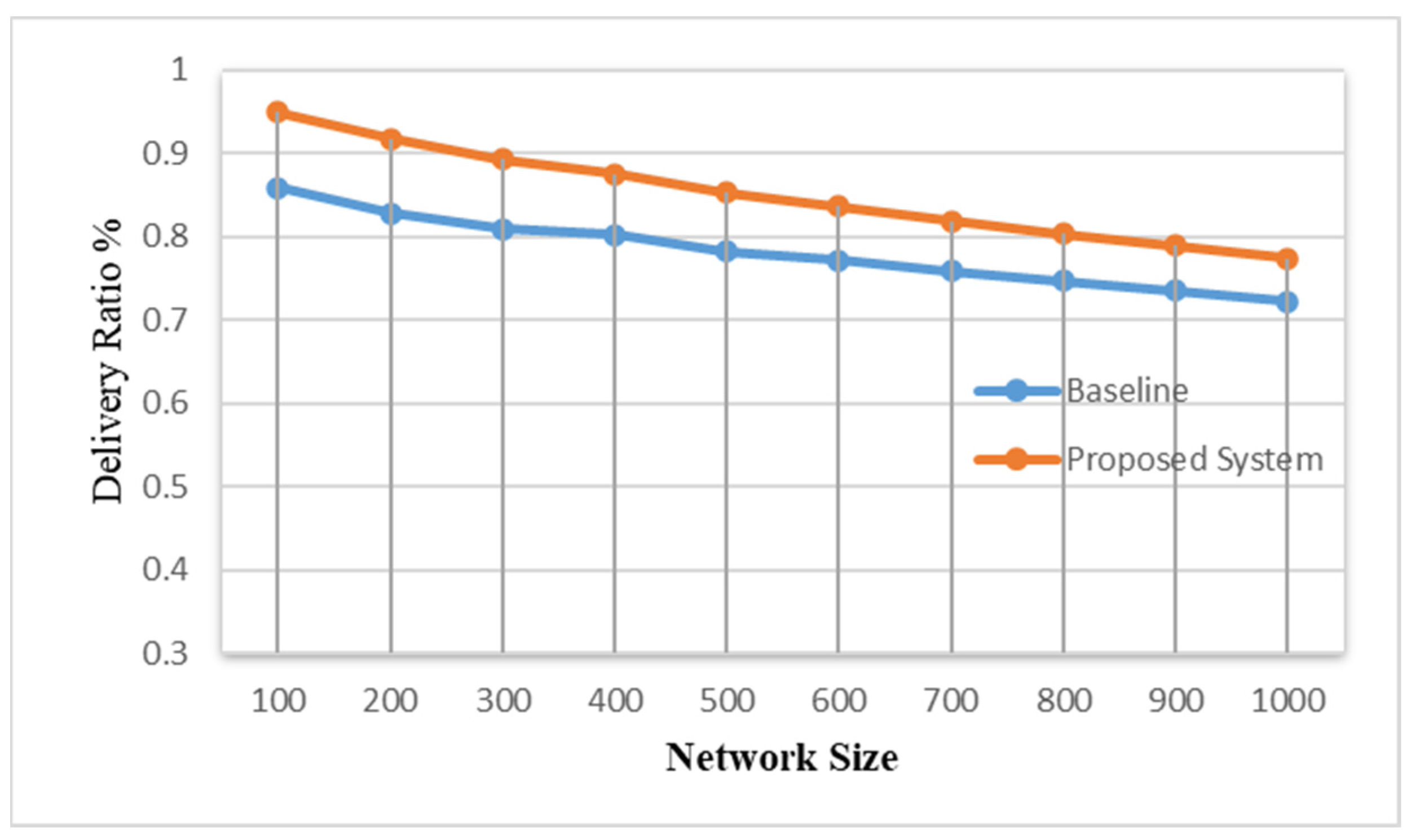
The delivery rate for all simulated networks is shown in Figure 6 and Figure 7. Figures display the overall success rate for a network, including the generated traffic by devices located at the border of the area. Both figures clearly show that a better delivery rate is achieved using the proposed mechanism for all the network sizes. Almost a 10% increase in the delivery ratio is attained. This is a result of the success in delivering messages of out-of-range devices via the employed multi-hop strategy. The proposed system is seen to function better with more relaxing networks, a network with 5400 s send interval, as shown in Figure 7. This is expected as much amount of traffic in the network causes an increase in the chance of collisions and hence affects the overall efficiency of the network. This is also the case when the number of participating end devices is increased in the step of 100 devices, as can be seen in the figures. Moreover, it can be noted that distant devices in the one-hop system, standard LoRaWAN, ended up using a higher spreading factor with low bandwidth as a result of employing ADR. The use of such a setting leads to higher time on air for transmitted packets. This, however, would increase the possibility of collisions and consequently decrease the overall delivery rate.

Figure 6.
Packet Delivery rate for networks—one hour send interval.
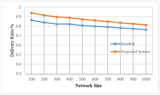
Figure 7.
Packet Delivery rate for networks—one and half an hour send interval.
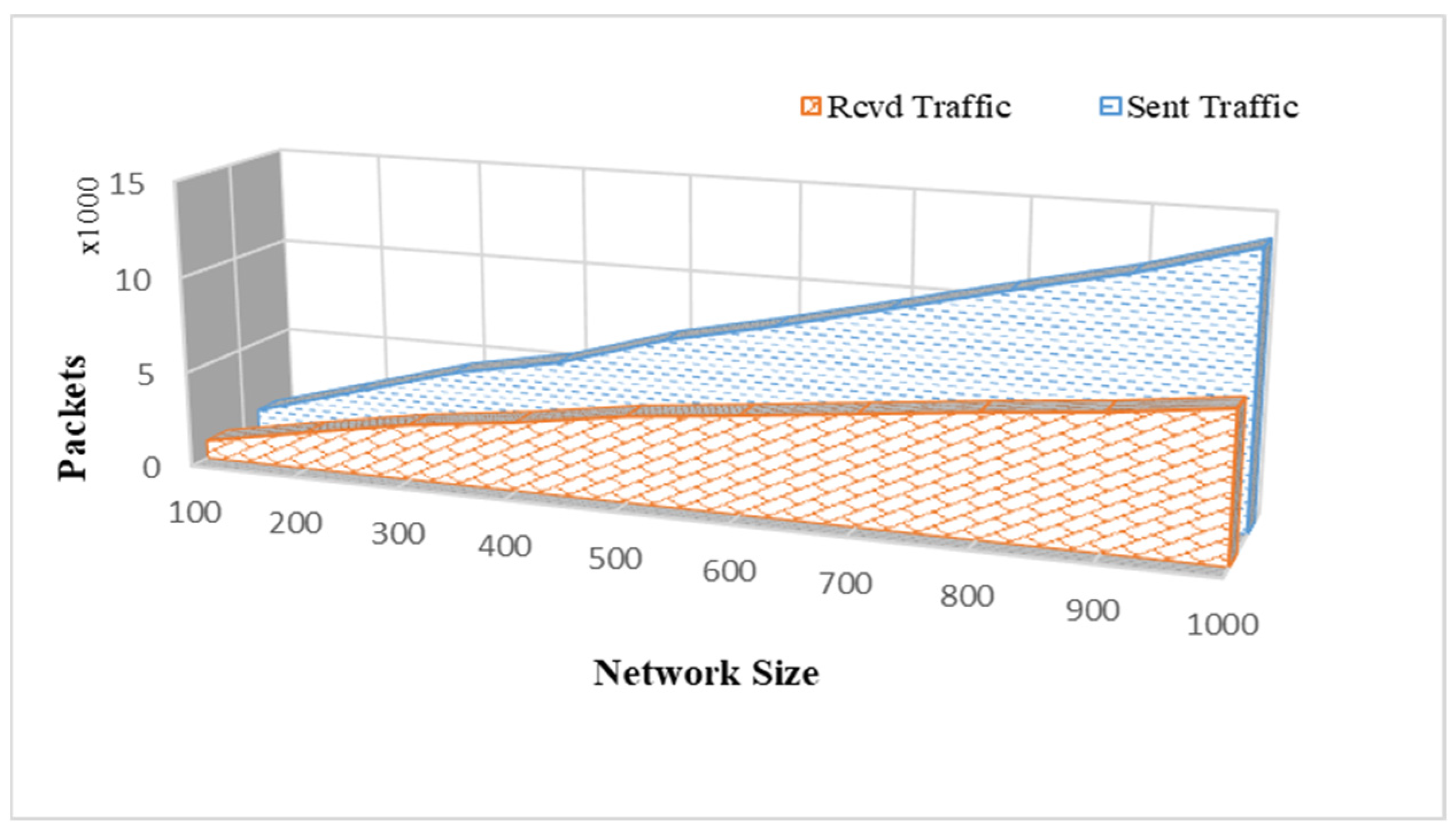
Figure 8 shows the amount of traffic that has been received successfully by the gateway via two hops using the proposed system in comparison to the overall traffic generated by out-of-range devices. Without the proposed system, the whole amount of sent traffic, illustrated in the figure with the blue line, would have been lost. The other line shows the delivered packets by the proposed system from faraway devices to the gateway. It shows the number of packets that have been saved by the proposed system. It has been achieved as a result of enforcing out-of-range devices to postpone their transmissions until they sense a transmission from one of their adjacent devices. The adjacent device is then used as a relaying device to forward the out-of-range device’s packet. As the figure shows, the ratio of delivered packets successfully to sent ones deteriorates as the network size grows, especially with 1000 participating devices. This has been experienced for both systems, as highlighted in Figure 6 and Figure 7, and it reveals the sensitivity of the LoRaWAN network regarding scalability. It is also due to the fact that devices located far away and still in the range of the gateway may use lower bandwidth with a larger spreading factor set using the ADR mechanism. Thus, the used network settings result in higher time on air, which increases the chance of collisions, especially with a larger number of devices in the network, and consequently affects the performance negatively.
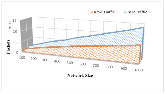
Figure 8.
Successfully received traffic from out-of-range devices.
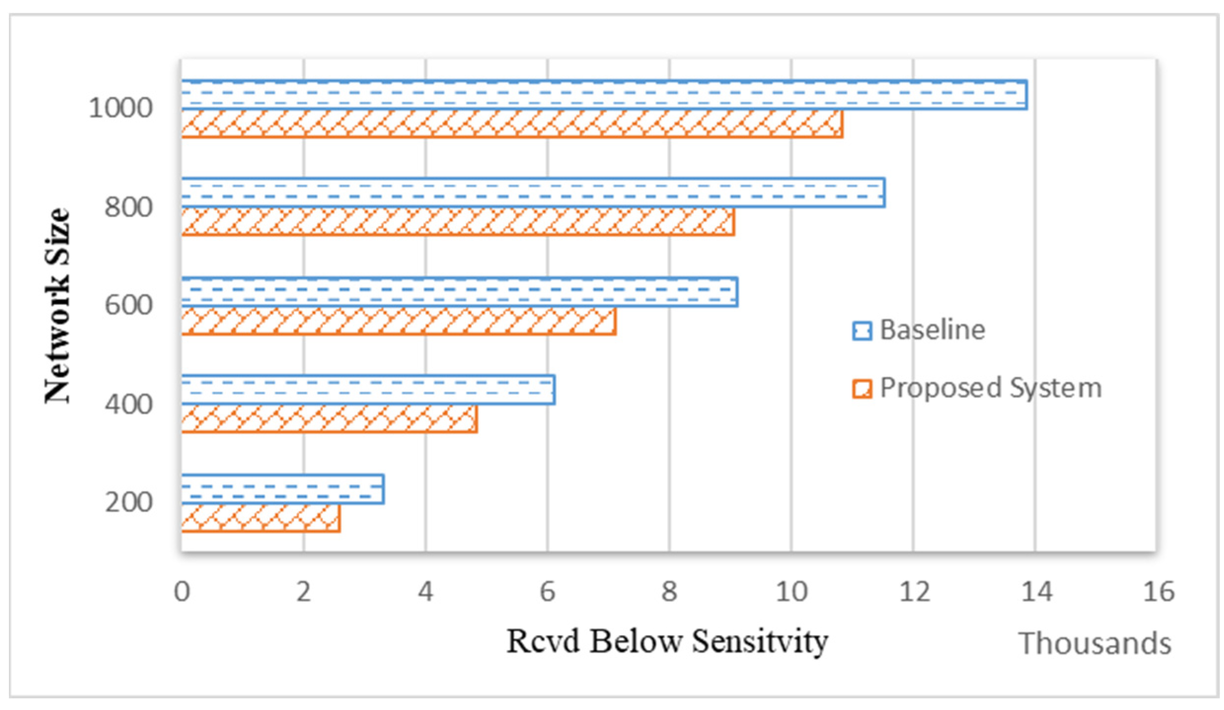
Figure 9 illustrates the performance of the proposed system in terms of the number of received packets by the gateway, which is under the receiver sensitivity. The proposed system achieves better results concerning this metric where less traffic is received below gateway radio sensitivity compared to the baseline, as depicted in the figure. This can be justified by the fact that the proposed system managed to deliver more traffic to the gateway successfully, as shown previously in Figure 6 and Figure 7. Therefore, the number of lost packets due to arriving below receiver sensitivity is decreased compared to the standard LoRaWAN. It is also due to the ability of distant devices in the proposed system to detect themselves as out of the gateway coverage and consequently adopt a lower spreading factor and delay their transmissions until they hear a signal from their neighbors. In addition, the higher number of lost packets due to arriving below sensitivity in the baseline system can be justified by the use of a higher spreading factor to reach the gateway. Nonetheless, the arriving signals are weak due to the long distance and consequently regarded below the sensitivity of the receiver.
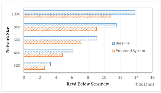
Figure 9.
Received packets below gateway’s sensitivity.
In order to improve traffic reliability, the proposed system allows data transmission using more than one hop for out-of-range devices. Thus, the impact of the developed mechanism on power consumption is investigated. Figure 10 shows the average daily energy usage for every single end device. The plotted result expresses the consumption calculated based on the radio spent time in a particular state. A LoRa device switches between three different states: receive, sleep, and transmit. As the figure illustrates, the proposed system consumed more power in contrast to the baseline. This is due to the fact the proposed system mechanism involves the relaying of out-of-range devices’ traffic, which consumes additional energy compared to the baseline, where devices are restricted to one-hop transmission. However, this can be seen as a cost for providing data reliability, especially for those devices that experience network isolation. Therefore, the proposed system is more favorable for such cases despite the higher power consumption. The figure also shows that the consumed power by the proposed system decreases inversely with the size of the network. The increase in the number of end devices means an increase in the opportunity of finding an end device transmitting a packet and, hence, decreasing the listening time for an out-of-range device trying to transmit. As a consequence, the average power consumption decreases as the number of end devices increases.
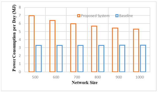
Figure 10.
Average daily power consumption for an end device.
5. Conclusions
In this paper, a multi-hop system for the LoRaWAN network, named Listen-To-Talk-based Multi-hop LoRaWAN (LTM-LoRaWAN), is proposed. It targets extending the coverage of the LoRaWAN network when increasing the number of gateways is infeasible due to gateway deployment constraints. The proposed system is dynamic and flexible enough to be adopted using different LoRaWAN applications that require an extended coverage capability while ensuring delivery reliability. The proposed system in this paper does not require any specific topology. It can be deployed using standard LoRaWAN end devices. The protocol ensures the ability of devices to discover themselves if they are out of the gateway coverage. This would be the trigger of the protocol operation. For out-of-coverage devices, the proposed system utilizes a procedure of transmission using a special type of medium access mechanism. The proposed system also entitles any standard end device that receives traffic from out-of-range devices to forward such traffic to a gateway while operating as a standard LoRaWAN device.
The performance of the proposed system is comprehensively evaluated using a network simulator. The result indicates the ability of the proposed system to increase network coverage while maintaining traffic reliability. The proposed system outperformed the standard LoRaWAN as it achieved a better delivery rate. The protocol also demonstrated scalability since it yielded a good performance while network sizes were increased. However, as a cost for providing data reliability and coverage extension, the proposed system showed higher energy consumption compared to the baseline system. In future work, the power consumption by the proposed system needs further investigation and analysis to improve the proposal’s performance regarding power consumption. This may involve investigating the listening time by out-of-range devices and the forwarding mechanism in order to decrease the consumed power. In addition, the impact of the proposed system on the traffic delay will be further investigated.
Funding
This research received no external funding.
Data Availability Statement
The data presented in this study are available on request from the corresponding author.
Conflicts of Interest
The author declares no conflict of interest.
References
- Alghamdi, A.M.; Khairullah, E.F.; Al Mojamed, M.M. LoRaWAN Performance Analysis for a Water Monitoring and Leakage Detection System in a Housing Complex. Sensors 2022, 22, 7188. [Google Scholar] [CrossRef] [PubMed]
- Al Mojamed, M. Smart Mina: LoRaWAN Technology for Smart Fire Detection Application for Hajj Pilgrimage. Comput. Syst. Sci. Eng. 2022, 40, 259–272. [Google Scholar] [CrossRef]
- Lalle, Y.; Fourati, M.; Fourati, L.C.; Barraca, J.P. Routing Strategies for LoRaWAN Multi-Hop Networks: A Survey and an SDN-Based Solution for Smart Water Grid. IEEE Access 2021, 9, 168624–168647. [Google Scholar] [CrossRef]
- Al Mojamed, M. On the Use of LoRaWAN for Mobile Internet of Things: The Impact of Mobility. Appl. Syst. Innov. 2022, 5, 5. [Google Scholar] [CrossRef]
- Yegin, A.; Seller, O. LoRaWAN Link Layer 1.0.4 Specification. 2020. Available online: https://lora-alliance.org/wp-content/uploads/2021/11/LoRaWAN-Link-Layer-Specification-v1.0.4.pdf (accessed on 15 February 2023).
- Benkahla, N.; Tounsi, H.; Song, Y.Q.; Frikha, M. Review and Experimental Evaluation of ADR Enhancements for LoRaWAN Networks. Telecommun. Syst. 2021, 77, 1–22. [Google Scholar] [CrossRef]
- Park, J.; Park, K.; Bae, H.; Kim, C.K. EARN: Enhanced ADR with Coding Rate Adaptation in LoRaWAN. IEEE Internet Things J. 2020, 7, 11873–11883. [Google Scholar] [CrossRef]
- Pan, M.; Chen, C.; Yin, X.; Huang, Z. UAV-Aided Emergency Environmental Monitoring in Infrastructure-Less Areas: LoRa Mesh Networking Approach. IEEE Internet Things J. 2021, 9, 2918–2932. [Google Scholar] [CrossRef]
- Abrardo, A.; Pozzebon, A. A Multi-Hop Lora Linear Sensor Network for the Monitoring of Underground Environments: The Case of the Medieval Aqueducts in Siena, Italy. Sensors 2019, 19, 402. [Google Scholar] [CrossRef] [PubMed]
- Alhomyani, H.; Fadel, M.; Dimitriou, N.; Bakhsh, H.; Aldabbagh, G.; Alkhuraiji, S. Multi-Hop Routing Protocols for Oil Pipeline Leak Detection Systems. Electronics 2022, 11, 2078. [Google Scholar] [CrossRef]
- Aslam, M.S.; Khan, A.; Atif, A.; Hassan, S.A.; Mahmood, A.; Qureshi, H.K.; Gidlund, M. Exploring Multi-Hop LoRa for Green Smart Cities. IEEE Netw. 2019, 34, 225–231. [Google Scholar] [CrossRef]
- Osorio, A.; Calle, M.; Soto, J.D.; Candelo-Becerra, J.E. Routing in LoRaWAN: Overview and Challenges. IEEE Commun. Mag. 2020, 58, 72–76. [Google Scholar] [CrossRef]
- Cotrim, J.R.; Kleinschmidt, J.H. LoRaWAN Mesh Networks: A Review and Classification of Multihop Communication. Sensors 2020, 20, 4273. [Google Scholar] [CrossRef]
- Sisinni, E.; Ferrari, P.; Fernandes Carvalho, D.; Rinaldi, S.; Marco, P.; Flammini, A.; Depari, A. LoRaWAN Range Extender for Industrial IoT. IEEE Trans. Industr. Inform. 2019, 16, 5607–5616. [Google Scholar] [CrossRef]
- Diop, M.; Pham, C. Increased Flexibility in Long-Range IoT Deployments with Transparent and Light-Weight 2-Hop LoRa Approach. In Proceedings of the Wireless Days, Manchester, UK, 24–26 April 2019. [Google Scholar]
- Tanjung, D.; Byeon, S.; Kim, D.H.; Deok Kim, J. OODC: An Opportunistic and On-Demand Forwarding Mechanism for LPWA Networks. In Proceedings of the International Conference on Information Networking, Barcelona, Spain, 7–10 January 2020; pp. 301–306. [Google Scholar]
- Le Sommer, N.; Touseau, L. LoRaOpp: A Protocol for Opportunistic Networking and Computing in LoRa Networks. In Proceedings of the 18th International Conference on Wireless and Mobile Computing, Networking and Communications (WiMob), Thessaloniki, Greece, 10–12 October 2022. [Google Scholar]
- Durand, T.G.; Booysen, M.J. Performance Evaluation of a Mesh-Topology LoRa Network. SSRN 4359315. 2023. Available online: https://papers.ssrn.com/sol3/papers.cfm?abstract_id=4359315 (accessed on 13 January 2023).
- Kaur, G.; Gupta, S.H.; Kaur, H. Evaluating and Optimizing the Performance of Dual-Hop LoRa Network Using Genetic Algorithm. In Proceedings of the 2nd International Conference on Innovative Practices in Technology and Management, Pradesh, India, 23–25 February 2022; pp. 663–668. [Google Scholar]
- Tran, H.P.; Jung, W.S.; Yoon, T.; Yoo, D.S.; Oh, H. A Two-Hop Real-Time LoRa Protocol for Industrial Monitoring and Control Systems. IEEE Access 2020, 8, 126239–126252. [Google Scholar] [CrossRef]
- Tran, H.P.; Jung, W.; Yoo, D.; Oh, H. Design and Implementation of a Multi-Hop Real-Time LoRa. Sensors 2022, 22, 3518. [Google Scholar] [CrossRef] [PubMed]
- Leonardi, L.; Lo Bello, L.; Mangiameli, E.; Patti, G. Towards Multi-Hop Real-Time Communications over LoRa Networks for Industrial Applications. In Proceedings of the IEEE International Conference on Emerging Technologies and Factory Automation, ETFA, Stuttgart, Germany, 6–9 September 2022; pp. 33–36. [Google Scholar]
- Leonardi, L.; Lo Bello, L.; Patti, G. MRT-LoRa: A Multi-Hop Real-Time Communication Protocol for Industrial IoT Applications over LoRa Networks. Comput. Commun. 2023, 199, 72–86. [Google Scholar] [CrossRef]
- LoRa Alliance LoRaWAN 1.1 Specification v1.1. 2017. Available online: https://resources.lora-alliance.org/technical-specifications/lorawan-specification-v1-1 (accessed on 26 November 2022).
- Slabicki, M.; Premsankar, G.; Di Francesco, M. Adaptive Configuration of Lora Networks for Dense IoT Deployments. In Proceedings of the IEEE/IFIP Network Operations and Management Symposium: Cognitive Management in a Cyber World, NOMS 2018, Taipei, Taiwan, 23–27 April 2018; pp. 1–9. [Google Scholar] [CrossRef]
- FloRa Framework. Available online: https://flora.aalto.fi/ (accessed on 12 April 2023).
- Petajajarvi, J.; Mikhaylov, K.; Roivainen, A.; Hanninen, T.; Pettissalo, M. On the Coverage of LPWANs: Range Evaluation and Channel Attenuation Model for LoRa Technology. In Proceedings of the 14th International Conference on ITS Telecommunications (ITST), Copenhagen, Denmark, 2–4 December 2015. [Google Scholar]
- Semtech WIRELESS & SENSING PRODUCTS Datasheet. Available online: https://semtech.my.salesforce.com/sfc/p/#E0000000JelG/a/440000001NCE/v_VBhk1IolDgxwwnOpcS_vTFxPfSEPQbuneK3mWsXlU (accessed on 20 June 2023).


Disclaimer/Publisher’s Note: The statements, opinions and data contained in all publications are solely those of the individual author(s) and contributor(s) and not of MDPI and/or the editor(s). MDPI and/or the editor(s) disclaim responsibility for any injury to people or property resulting from any ideas, methods, instructions or products referred to in the content. |
© 2023 by the author. Licensee MDPI, Basel, Switzerland. This article is an open access article distributed under the terms and conditions of the Creative Commons Attribution (CC BY) license (https://creativecommons.org/licenses/by/4.0/).