Article

The Analysis of Permanent Magnet Vernier Synchronous Machine Vibration and Noise

School of Electrical and Electronic Engineering, Harbin University of Science and Technology, Harbin 150080, China
*
Author to whom correspondence should be addressed.
Electronics 2023, 12(20), 4341; https://doi.org/10.3390/electronics12204341
Submission received: 14 September 2023 / Revised: 9 October 2023 / Accepted: 18 October 2023 / Published: 19 October 2023

Abstract

:
The permanent magnet vernier synchronous machine (PMVSM) has the characteristics of high torque density and high power density and has advantages in the field of low-speed and high-torque applications. The PMVSM utilizes rich harmonics for torque enhancement, but it can also cause an increase in radial electromagnetic force and vibration noise. In this paper, we take a 12-slot 10-pole PMVSM as an example to analyze the source of radial electromagnetic force, vibration and noise. The electromagnetic finite-element model and structural finite-element model of the PMVSM are established for calculation. Through the analysis and calculation of two-dimensional electromagnetic fields, the radial electromagnetic force distribution of the PMVSM is obtained. We derive the radial electromagnetic force formula of the PMVSM and verify the correctness of the formula through harmonic analysis of the radial electromagnetic force. The sources of radial electromagnetic forces at various orders and frequencies within the PMVSM are analyzed and summarized by coupling the radial electromagnetic force obtained from the electromagnetic finite-element model to the structural finite-element model and conducting electromagnetic vibration harmonic response analysis on the PMVSM. The measured acceleration spectrum of the prototype is compared with the finite-element method (FEM) results, verifying the correctness of the finite-element simulation results for electromagnetic vibration.

1. Introduction

With the widespread research and application of rare earth materials, the permanent magnet synchronous motor (PMSM) plays an important role in industrial production and transportation. For a PMSM, electromechanical energy conversion and stable output torque can only be carried out when the number of pole pairs of the stator and rotor magnetic fields is equal. This feature makes the permanent magnet vernier synchronous machine (PMVSM) easy to design and analyze, and machine design and optimization can be achieved through magnetic path and field operations. However, for low-speed and high-torque direct drive applications, the number of stator slots in a PMSM becomes very large, resulting in a larger machine volume and a decrease in power density and torque density. A PMVSM based on the principle of magnetic field modulation can achieve low-speed and high-torque output with fewer stator slots [1,2,3]. Due to the unequal number of pole pairs in the stator and rotor magnetic fields of the PMVSM, magnetic field modulation is carried out by adjusting the number of magnetic modulation teeth, which makes the structure of the PMVSM flexible and diverse [4]. Due to the unequal number of pole pairs between the stator and rotor magnetic field of a PMVSM, it differs from a PMSM in terms of electromagnetic characteristics.
In practical applications, there are strict restrictions on the vibration and noise of PMSMs. Excessive noise can cause health damage to users. The study of PMSM vibration and noise is currently a research hotspot. Radial electromagnetic force can cause periodic deformation and vibration of the stator core, and the radial electromagnetic force wave that varies with time and space is the main cause of machine noise [5]. Rotor step skewing can effectively reduce the vibration noise of the PMSM. By establishing an analytical formula for radial electromagnetic force waves, the impact of the number of skewing segments on vibration noise can be analyzed [6]. The stator current has harmonic components, which can affect the vibration and noise of the PMSM. By studying the amplitude variation in the lowest-order spatial radial electromagnetic force wave caused by current harmonics and the direct axis current component of the stator input current, the relationship between noise and the vibration peak can be analyzed and the radial electromagnetic force of the machine can be reduced [7,8]. In addition, the current harmonics of the inverter can also have an impact on electromagnetic noise [9]. The variable speed transmission of the machine can also cause the stator core vibration of the permanent magnet synchronous machine. By analyzing the model and electromechanical pulse response, the relationship between stator current and stator acceleration is established [10]. The shape of the stator teeth can influence the distribution of the radial electromagnetic force higher-order harmonics, causing the machine to enter low-mode vibration, thereby optimizing the vibration reduction in the PMSM [11]. For machines with built-in permanent magnets, the geometric shape of the magnetic isolation bridge affects the distribution of the magnetic field and has an impact on the spatial–temporal distribution of radial electromagnetic force. Optimizing the design of the magnetic isolation bridge for the built-in permanent magnet machine can reduce low-order radial electromagnetic forces and vibration noise. [12,13]. A mathematical model for analyzing the radial electromagnetic force density of surface-mounted permanent magnet machines can be established to obtain the amplitude frequency and order and further determine the resonance situation, revealing the influence of PMSM parameters on vibration noise [14,15]. Structurally, the vibration noise of a machine is related to the shape of the permanent magnet poles. The pole arc coefficient of permanent magnets affects the amplitude of radial electromagnetic force. By establishing a permanent magnet shape function and adjusting the structure of the permanent magnet, reductions in the vibration and noise of the machine can be achieved. This method is suitable for surface-mounted and built-in permanent magnet machines [16]. The length of the air gap of a PMSM has a significant impact on its performance. When the length of the air gap of the PMSM undergoes deformation, both the radial electromagnetic force and vibration noise of the machine change, and the low-frequency radial electromagnetic force content increases, resulting in an increase in vibration noise [17]. The harmonic content of stator current affects the distribution of non-sinusoidal magnetic field flux, and controlling stator current can reduce PMSM vibration noise [18]. By using analytical methods to obtain the air gap flux density and radial electromagnetic force density of the PMSM and then using the method of continuously segmented variable pole width, the radial electromagnetic force and bending moment of the PMSM can be reduced [19]. Taking into account the anisotropy of stator materials during machine modal analysis can improve the accuracy of finite-element calculations. Through analysis of current harmonic types, it is found that (6k ± 1) times the fundamental frequency can affect the vibration and noise peaks [20]. In addition, for an external rotor PMSM, adjusting the slot width can play a role in vibration reduction and noise reduction, as verified through finite-element method calculation [21]. At present, PMSM vibration noise is believed to be related to the stator structure and input current. Adjusting the stator structure and current of the PMSM can reduce vibration noise. Using control methods to reduce the harmonic content of low-order radial electromagnetic force can also achieve reductions in the vibration and noise of a PMSM.
Due to the magnetic tooth structure of the PMVSM, the uneven degree of the air gap is exacerbated by the concave convex geometric structure, and the harmonic content in the air gap flux density becomes more abundant. The interaction of harmonic magnetic fields in the air gap generates radial electromagnetic forces of different orders and frequencies. This paper focuses on the influence of the magnetic field modulation principle of the PMVSM on the radial electromagnetic force and vibration noise. By deriving the radial electromagnetic force formula of a PMVSM considering stator slotting and rotor saliency effects, the harmonic decomposition of the radial electromagnetic force is obtained to determine the source of its harmonic magnetic field, and the influence of stator magnetic teeth on the radial electromagnetic force is studied. The low-order low-frequency radial electromagnetic force has a significant impact on the vibration of the machine, while the high-frequency magnetic field has a significant impact on the machine noise. The FEM is used to simulate the modal and vibration noise of the PMVSM, obtain the vibration mode and natural frequency of the machine and compare it with the radial electromagnetic force to determine the resonance situation of the machine. Finally, the accuracy of the finite-element calculation is confirmed through prototype experiments.
In Section 2 of the paper, we establish a two-dimensional finite-element model of a PMVSM. In Section 3, we derive the radial electromagnetic force formula of the PMVSM and determine the spatiotemporal distribution of the radial electromagnetic force of the machine. In Section 4, we analyze the radial electromagnetic force of the PMVSM. The correctness of the radial electromagnetic force formula in Section 3 is verified through harmonic decomposition; using modal analysis and the FEM to evaluate vibration and noise, the vibration modes of the machine at different frequencies and the noise at rated speed are obtained. And in Section 5, the vibration and noise of the machine are determined through experiments to verify the correctness of the FEM analysis.

2. The Structure of the PMVSM

The pole pairs of the magnetic field of the stator and rotor of a PMVSM are not equal. By matching the pole pairs of the magnetic field with a reasonable number of modulation teeth, a stable rotating air gap magnetic field is generated. The PMVSM in this paper has an external rotor structure; the stator is fixed by a fixed shaft, and the rotor of the machine rotates stably through the casing bearing and the stator fixed shaft bearing. In this paper, a 12-slot 10-pole PMVSM is built, and the number of pole pairs in the rotor magnetic field is 19. The permanent magnet is built into the external rotor. The PMVSM structure is shown in Figure 1.
The simulation model and prototype machine are made based on the PMVSM design parameters. The speed of the machine at a fundamental frequency of 95 Hz is 300 rpm and the rated power is 750 W. The structural parameters of the PMVSM are shown in Table 1.

3. The Calculation of Radial Electromagnetic Force

There is a significant difference in structure between a PMVSM and a traditional PMSM, as the number of pole pairs of the stator and rotor of the PMVSM is not equal. The stator and rotor magnetic field in the PMVSM are set by adjusting the magnetic modulation teeth so that the air gap can produce a stable rotating magnetic field and output torque. The number of pole pairs in the stator and rotor of a PMVSM meets the principle of magnetic field modulation, and the specific quantity relationship is
P t = P r + P s
where the P t is the number of the modulation teeth, P r is the number of the rotor pole pairs, and P s is the number of stator winding pole pairs.
The magnetomotive force of the PMVSM rotor can be calculated as follows:
F μ = 4 B P M h P M μ 0 μ π sin ( μ α p π 2 )
where the B P M is the remanence of the permanent magnet, h P M is the thickness of the permanent magnet, μ 0 is the relative permeability of air, α p is the pole arc coefficient of the permanent magnet, and μ is the harmonic coefficient of rotor magnetomotive force.
For a fractional slot concentrated winding PMVSM, the magnetomotive force of the stator winding can be calculated as follows:
F ν = 1 ν 2 2 N k ω ν π P r I ϕ k ω ν = sin ( ν 2 π P t )
where the N is the number of series turns per phase of stator winding, k ω ν is the winding factor of the ν th harmonic coefficient of stator magnetomotive force, and I ϕ is the effective value of the current. υ is the harmonic coefficient of the stator magnetomotive force.
Considering the slotted stator, the air gap permeance is
Λ ( θ ) = Λ 0 + k = 1 , 2 , 3 , Λ k cos ( k P t θ )
where Λ 0 is the DC component of air gap permeance, Λ k is the k th harmonic air gap permeance amplitude. θ is the angle between the centerline of the rotor permanent magnet and the centerline of the stator teeth, which is the relative position angle of the stator and rotor.
Considering the rotor saliency effect caused by the built-in permanent magnet, the air gap relative permeability is
λ ( θ ) = λ 0 + m = 1 , 2 , 3 , λ m cos ( 2 m ω 2 m P r θ )
where the λ 0 is the DC component of air gap relative permeability, λ m is the amplitude of the m th harmonic relative permeability generated by the rotor salient pole, and ω is the mechanical angular frequency of the PMVSM.
Generally speaking, the larger the air gap flux density, the higher the torque and efficiency of the machine. However, excessive air gap flux density can increase the vibration noise of the machine. The PMVSM radial component of air gap flux density can be calculated as follows:
B r ( θ , t ) = [ μ = 1 , 3 , 5 , F μ cos ( μ ω t μ P r θ ) + ν = 1 , 5 , 7 , F ν cos ( ω t ν P r θ + ϕ ) ] [ Λ 0 + k = 1 , 2 , 3 , Λ k cos ( k P t θ ) ] [ λ 0 + m = 1 , 2 , 3 , λ m cos ( 2 m ω 2 m P r θ ) ]
According to the Maxwell tensor method, the radial electromagnetic force density of the machine is
f r ( θ , t ) = 1 2 μ 0 ( B r 2 ( θ , t ) B t 2 ( θ , t ) ) 1 2 μ 0 B r 2 ( θ , t ) = 1 2 μ 0 { [ μ = 1 , 3 , 5 , F μ cos ( μ ω t μ P r θ ) + ν = 1 , 5 , 7 , F ν cos ( ω t ν P r θ + ϕ ) ] [ Λ 0 + k = 1 , 2 , 3 , Λ k cos ( k P t θ ) ] [ λ 0 + m = 1 , 2 , 3 , λ m cos ( 2 m ω 2 m P r θ ) ] } 2

4. The Vibration and Noise of the PMVSM

The vibration of a PMVSM is influenced by two factors: one is the inherent parameters of the machine itself, and the other is the excitation force. The excitation force of the machine is also affected by two aspects: on the one hand, it is mechanical, such as machine balance issues, torque ripple of load type prime movers, machining accuracy, etc.; on the other hand, it is electromagnetic, mainly radial electromagnetic force. When the frequency of the radial electromagnetic force is consistent with the natural frequency of the machine, the machine will resonate and the noise will increase. To avoid resonance, it is necessary to make the frequency of radial electromagnetic force different from the natural frequency of the machine.

4.1. The Radial Electromagnetic Force of the PMVSM

The deformation of the machine stator is affected by the radial electromagnetic force, which is the main reason electromagnetic vibration noise is generated by the machine. Studying the radial electromagnetic force of a machine is the foundation for studying the vibration and noise of the machine.
The magnitude of electromagnetic vibration caused by the radial electromagnetic force on the stator is directly proportional to the amplitude of the radial electromagnetic force and inversely proportional to the fourth power of the electromagnetic force order. Therefore, the higher the spatial order, the less likely it is to cause vibration.
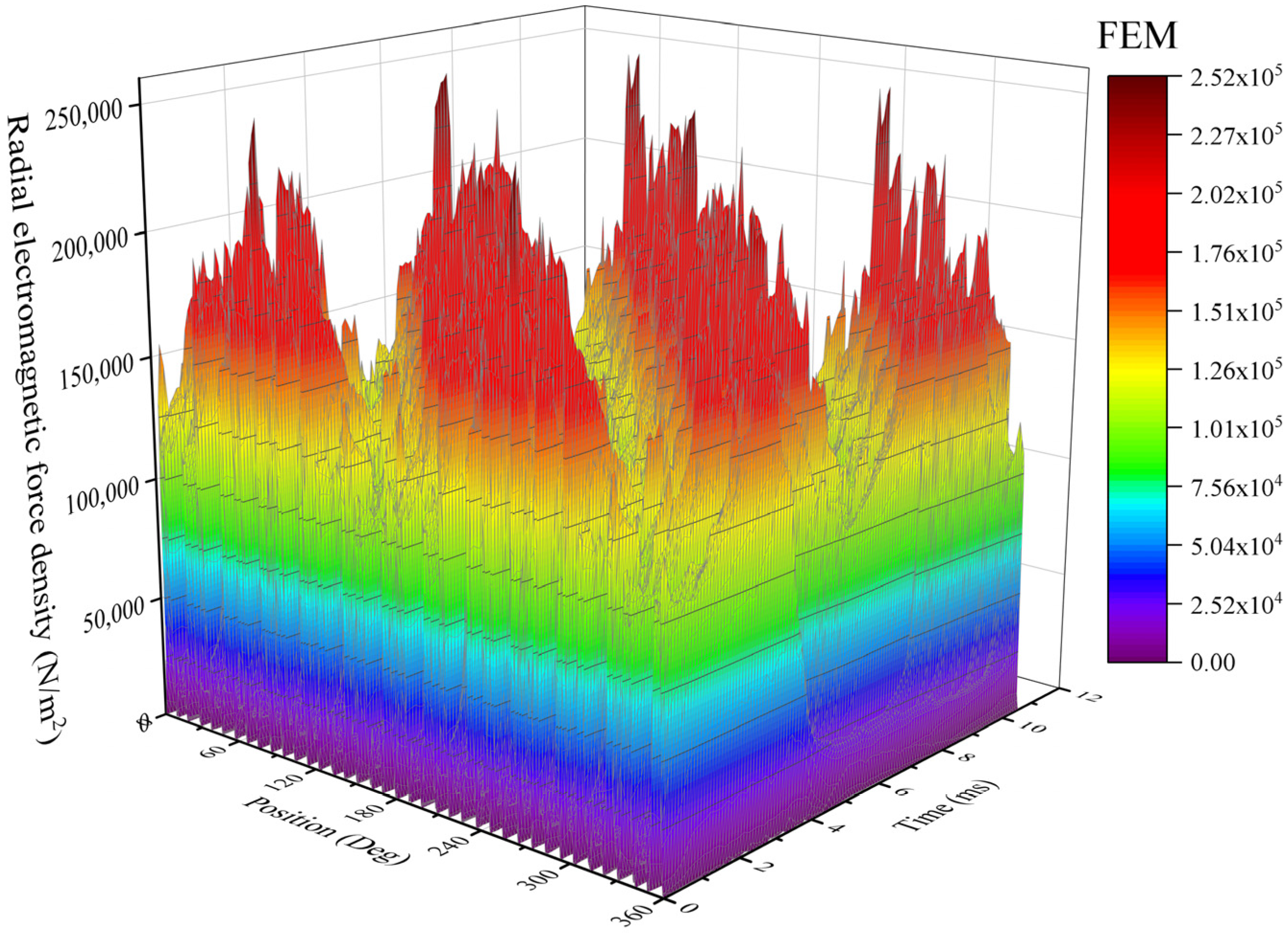
A 2D simulation model of the PMVSM is established to obtain the radial electromagnetic force via FEM analysis. The spatiotemporal distribution of radial electromagnetic force is shown in Figure 2.
The spatial–temporal distribution of the radial electromagnetic force is obtained through harmonic decomposition. In the Figure 3 (A, Bf), A represents the spatial order and B represents the temporal order. The harmonic content of the radial electromagnetic force is shown in Figure 3.
The harmonic content of radial electromagnetic force in Figure 3 is higher than that of traditional PMSMs. It can be seen that the magnetic field modulation effect introduces more harmonics into the PMVSM, resulting in a rich and complex harmonic content of radial electromagnetic force. The smaller the spatial and temporal orders, the greater the impact on machine vibration. Therefore, the radial electromagnetic force harmonics of the PMVSM, (−2, 2f), (10, 2f), (−4, 4f), (8, 4f), (6, 6f), (8, 8f) and (−12, 12f), are the main harmonics causing machine vibration. The source of the radial electromagnetic force density harmonic content can be obtained with Equations (A1)–(A3) in Appendix A. Through the analysis of the sources of radial electromagnetic force in Table A1 in Appendix A, it can be seen that the tooth effect of the stator magnetic teeth of a PMVSM is more pronounced than that of PMSM. A large amount of radial electromagnetic force is generated by the tooth harmonic magnetic field, increasing the possibility of machine vibration.

4.2. The Modal Analysis and Vibration and Noise of the PMVSM

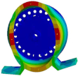
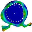
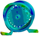
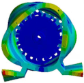
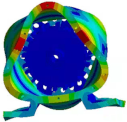
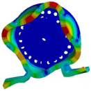
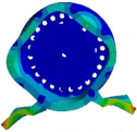
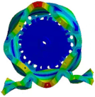
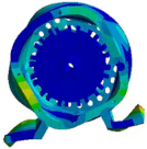
When the frequency of radial electromagnetic force harmonics is close to the natural frequency of the machine stator, resonance will occur in the stator, which will cause a more serious vibration response. Therefore, modal analysis is a key step in studying the electromagnetic vibration noise of the machine. Through modal analysis, the modal shapes and natural frequencies of each order of the machine stator structure can be clearly understood, and the possibility of resonance in the machine can be analyzed. In this paper, we use the modal calculation method under the free state of the stator to solve this. In Table 2, the M in the order column (M, N) represents the radial vibration mode, and N represents the axial vibration mode. Before the modal analysis, the PMVSM stator winding is equivalent to a mass point added to the stator core. The stator core and casing are analyzed together; the stator modal shapes and natural frequencies of the PMVSM are shown in Table 2.
The frequencies of the radial electromagnetic force harmonics are mainly 2f = 190 Hz, 4f = 380 Hz, 6f = 570 Hz, 8f = 760 Hz and 12f = 1140 Hz, which are not consistent with the natural frequencies of the PMVSM, so the PMVSM does not resonate.
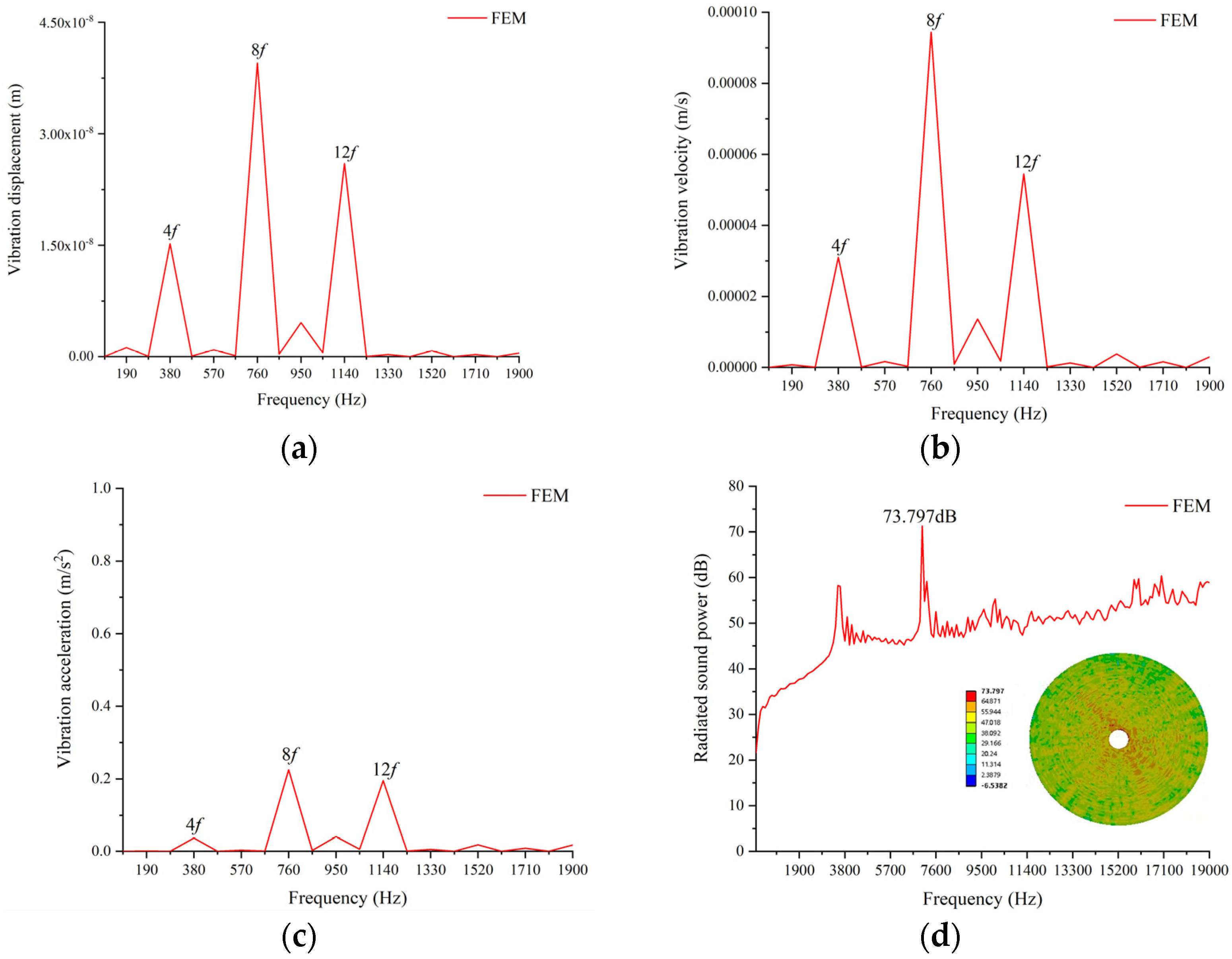
Figure 4 shows the vibration displacement, vibration velocity and vibration acceleration wave form of the PMVSM, which are mainly concentrated at 4f = 380 Hz, 8f = 760 Hz and 12f = 1140 Hz. Due to the low order and large amplitude of the radial electromagnetic force harmonic components of 4f = 380 Hz, 8f = 760 Hz and 12f = 1140 Hz, the harmonic content of the vibration displacement, vibration velocity and vibration acceleration at the corresponding frequency increases. The maximum noise of the PMVSM at rated speed is 73.797 dB, and the maximum noise point occurs in the high-frequency region.

5. PMVSM Modal and Noise Experiment

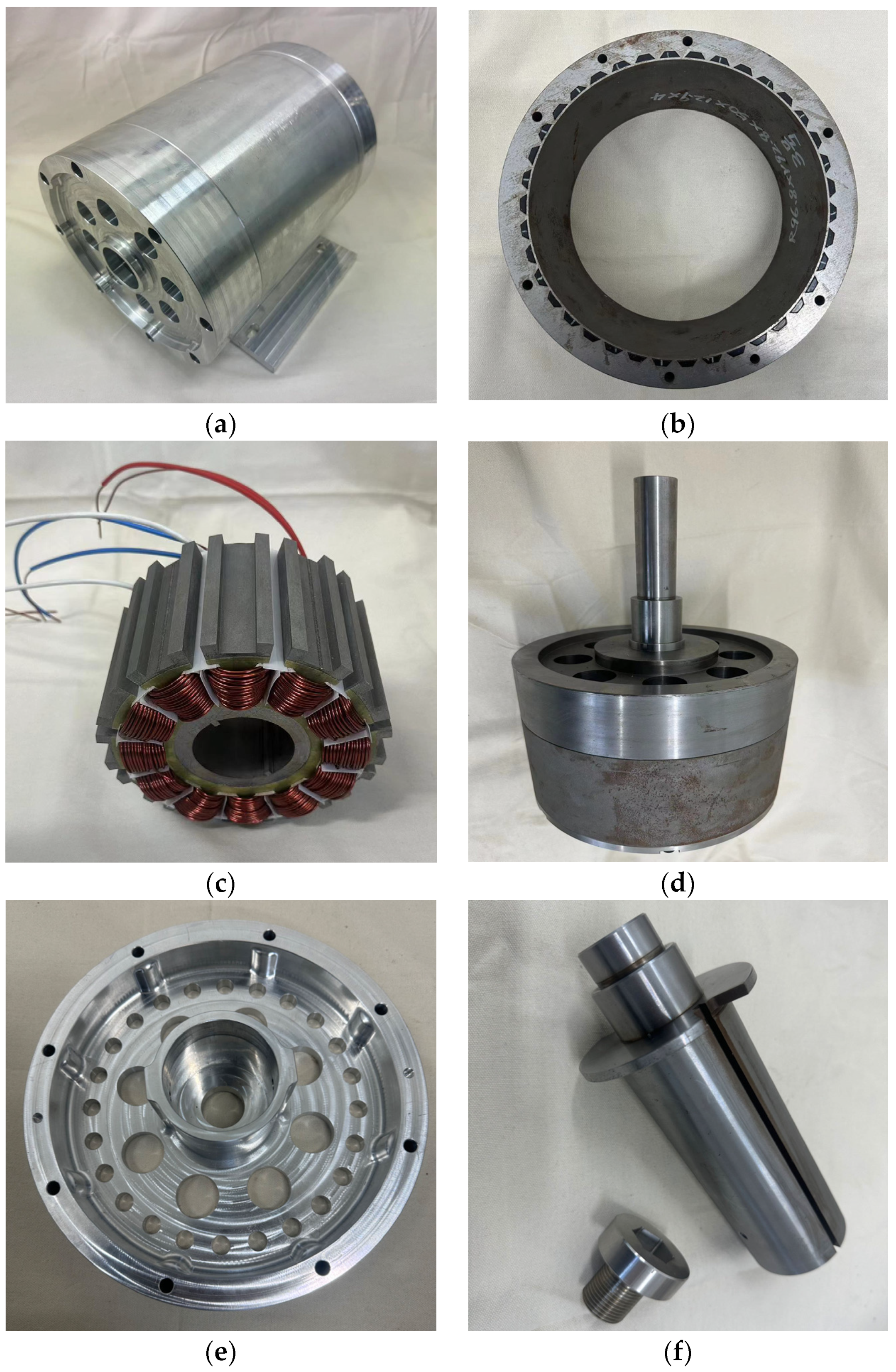
We designed a prototype based on the structural parameters of the PMVSM. The machine structure is an external rotor structure, and the output shaft is connected with the experimental platform through a coupling. The main components of the PMVSM are shown in Figure 5.
The prototype PMVSM is dragged with a six-pole rated power of 3 kW prime mover, and the no-load back-EMF of the prototype PMVSM at a rated speed of 300 rpm is obtained. The no-load back-EMF of PMVSM has good sinusoidal characteristics. Through comparison, it is found that the simulation results are consistent with the experimental results, proving that the actual performance of the machine is consistent with the design performance. The no-load experiment of the PMVSM is shown in Figure 6.
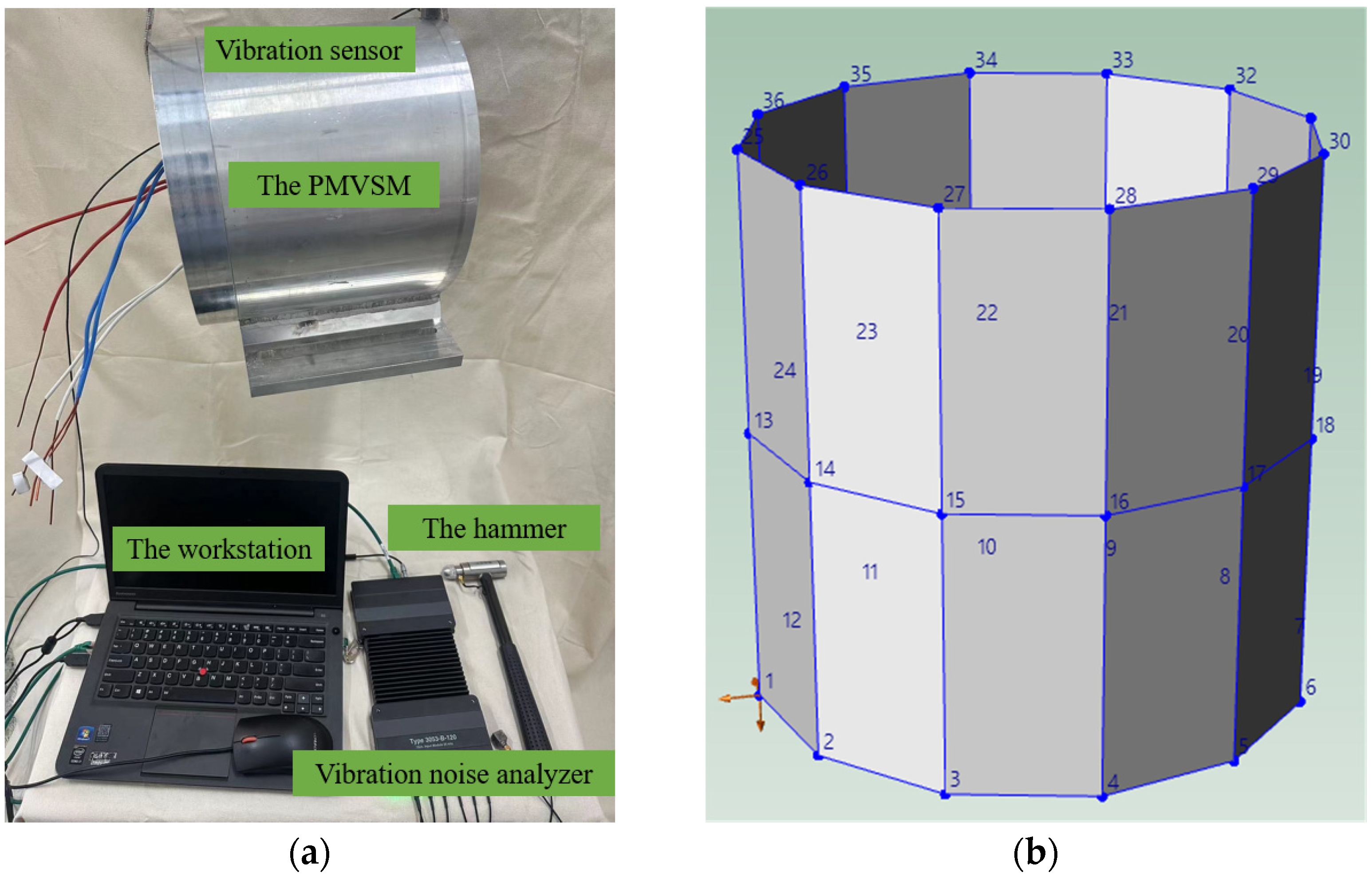
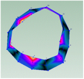
We used the hammer method to conduct modal experiments on the prototype PMVSM. The force hammer strikes the PMVSM to vibrate, inputting an excitation signal at each specific position. The response signal is collected by the machine, allowing the sensor to obtain the machine modal vibration mode and natural frequencies. The PMVSM casing is divided into 36 areas (vibration point) in both the axial and radial directions, and a hammer is used to evenly strike each area three times to obtain the natural frequency and modal shape of the machine. The vibration points need to be evenly distributed on the surface of the casing, and there should be as many as possible to ensure the accuracy of the measurement. Figure 7b shows the internal software of the measurement system. The model only displays the distribution of the vibration points on the surface of the casing and does not represent the specific structure of the measured object. The modal test platform is shown in Figure 7.
The stable frequency response curve of the PMVSM is obtained after conducting multiple sets of tapping tests on the machine’s tapping points. The stable frequency response curve is shown in Figure 8.
Through the PMVSM modal experiments, the modes of the machines, (2, 0), (2, 1), (3, 0), (3, 1), (4, 0) and (4, 1), are obtained, and the corresponding frequencies obtained are shown in Figure 8. Through comparison with Table 2, it is found that the modal experimental results are basically consistent with the simulation results. The machine modal experiment verifies the correctness of finite-element calculation. The experimental results for the modal shapes and natural frequencies are shown in Table 3. The modes of the modal shapes and natural frequencies, as shown in the left row, are (2, 0), (3, 0) and (4, 0) respectively.
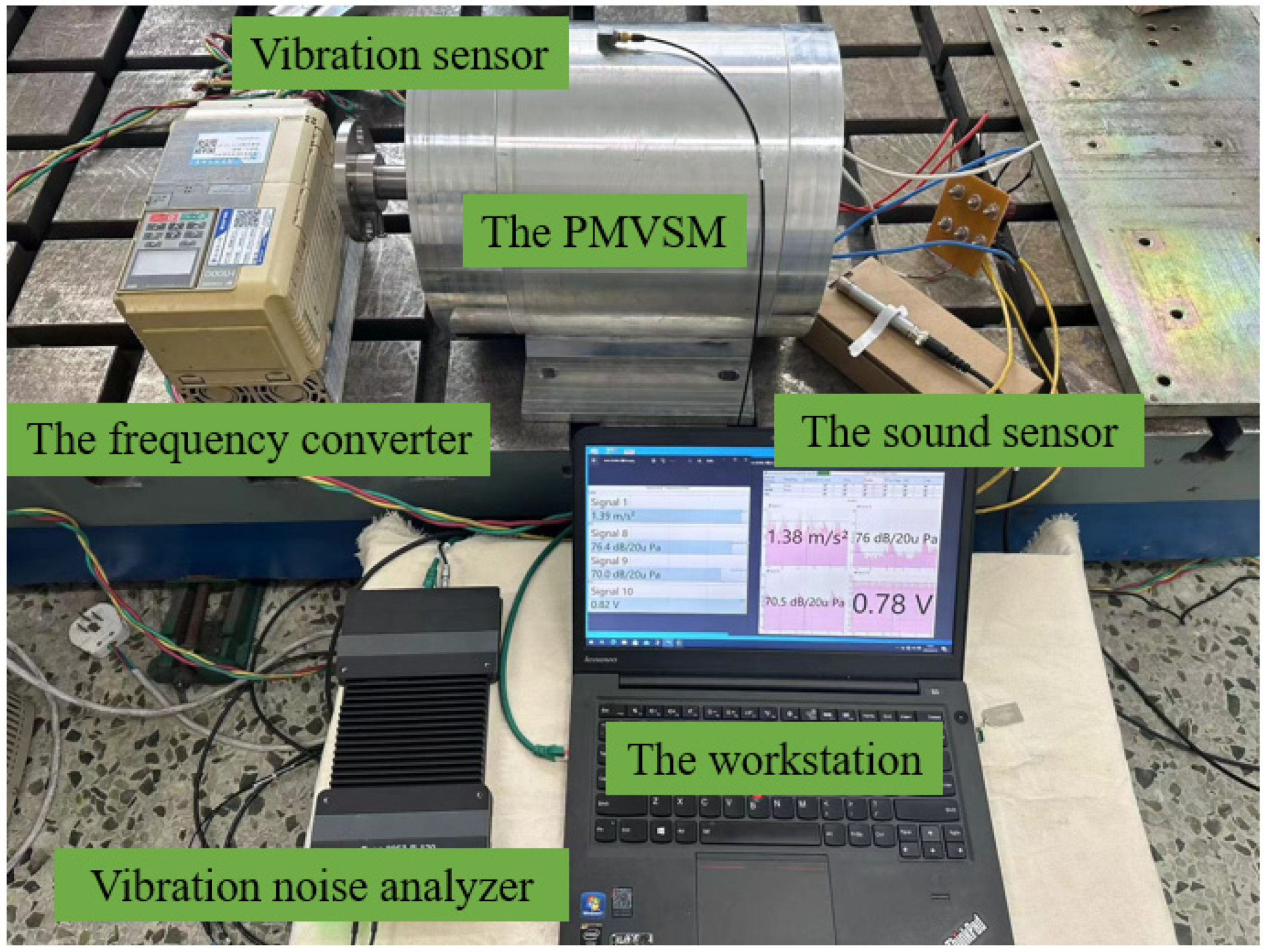
The PMVSM is connected to the controller, the frequency is set to 95 Hz, and the PMVSM speed is set to 300 rpm. The vibration acceleration of the PMVSM is obtained through sensors on the surface of the casing, and the noise of the PMVSM at the rated speed of 300 rpm is obtained through sound sensors. The noise test platform is shown in Figure 9.
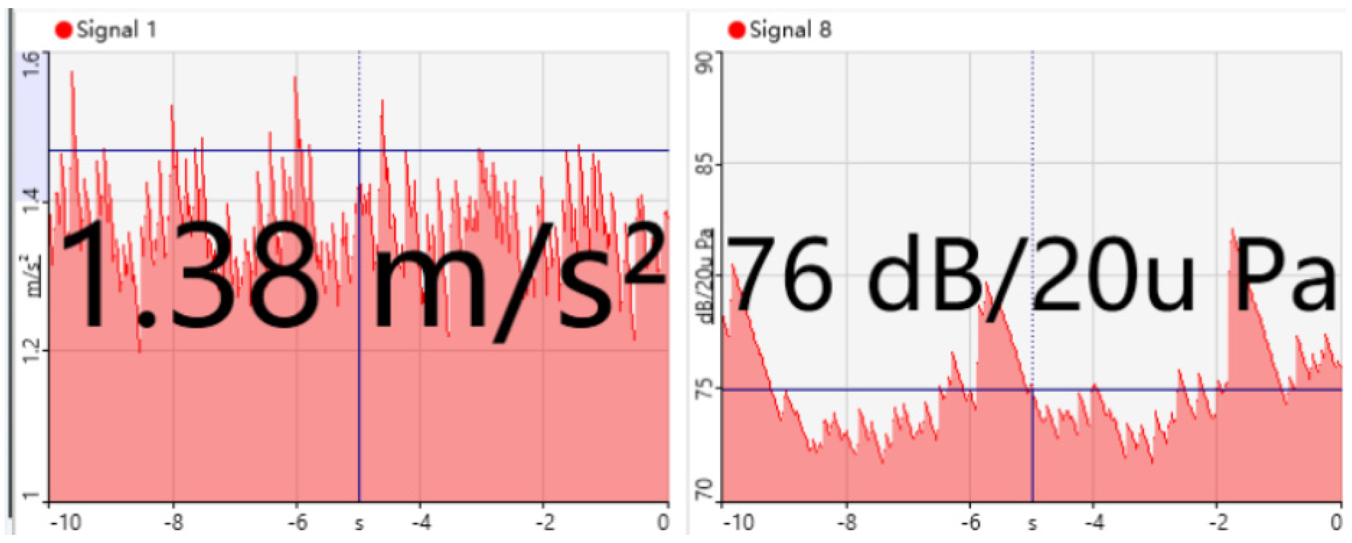
The noise of the motor at the rated speed of 300 rpm obtained through experiments is 76 dB. The error between noise experimental data and simulation is 2.2 dB, with an error rate of 2.9%. The machine noise is shown in Figure 10.

6. Conclusions

In this paper, we study the radial electromagnetic force and vibration noise of a PMVSM and derive a formula for the radial electromagnetic force considering the effects of stator slotting and rotor saliency. The spatiotemporal distribution characteristics of the radial electromagnetic force are obtained through the FEM, and the source of the radial electromagnetic force is analyzed. The stator magnetic modulation teeth of the PMVSM have a significant effect on magnetic field modulation, and the main source of radial electromagnetic force in the machine includes the tooth harmonic magnetic field, which increases the possibility of machine vibration. Then, finite-element simulation is conducted on the modal and vibration noise of the PMVSM to obtain the vibration mode and natural frequency. Due to the low-order and high-amplitude harmonic components of radial electromagnetic force being consistent with the frequency distribution of machine vibration characteristics, the harmonic content of corresponding vibration displacement, vibration velocity and vibration acceleration increases at 4f, 8f and 12f. The vibration modes (2, 0) and (2, 1) do not coincide with the radial electromagnetic force frequency of the machine in frequency, so the machine does not resonate. Finally, the vibration mode, frequency and noise measured in the experiment are consistent with the finite-element results, verifying the accuracy of the finite-element calculation.

Author Contributions

Conceptualization, F.Y.; methodology, F.Y., D.L., Y.Z., L.W., B.Y. and F.Z.; software, F.Y., D.L. and Y.Z.; validation, F.Y.; formal analysis, F.Y. investigation, F.Y. and D.L.; resources, F.Y.; data curation, F.Y.; writing—original draft preparation, F.Y. and D.L.; writing—review and editing, F.Y. and D.L.; visualization, F.Y., D.L. and Y.Z.; supervision, L.W., B.Y. and F.Z.; project administration, F.Y. All authors have read and agreed to the published version of the manuscript.

Funding

This research received no external funding.

Data Availability Statement

Data are not available in a publicly accessible repository and they cannot be shared under request.

Conflicts of Interest

The authors declare no conflict of interest.

Appendix A

By expanding Equation (7), we can obtain the various components of radial electromagnetic force. Negative harmonic order in the radial electromagnetic force space indicates that the direction of radial electromagnetic force is opposite to the direction of machine rotation.
F μ 1 F μ 2 Λ 0 2 λ 0 2 4 μ 0 cos [ ( μ 1 ± μ 2 ) ω t ( μ 1 ± μ 2 ) P r θ ] F μ 1 F μ 2 Λ 0 Λ k λ 0 2 4 μ 0 cos { ( μ 1 ± μ 2 ) ω t [ ( μ 1 ± μ 2 ) P r ± k P t ] θ } F μ 1 F μ 2 λ 0 λ m Λ 0 2 4 μ 0 cos { [ ( μ 1 ± μ 2 ) ± 2 m ] ω t [ ( μ 1 ± μ 2 ) ± 2 m ] P r θ } F μ 1 F μ 2 Λ k 1 Λ k 2 λ 0 2 16 μ 0 cos { ( μ 1 ± μ 2 ) ω t [ ( μ 1 ± μ 2 ) P r ± ( k 1 ± k 2 ) P t ] θ } F μ 1 F μ 2 Λ 0 Λ k λ 0 λ m 8 μ 0 cos { [ ( μ 1 ± μ 2 ) ± 2 m ] ω t [ ( μ 1 ± μ 2 ) P r ± 2 m P r ± k P t ] θ } F μ 1 F μ 2 λ m 1 λ m 2 Λ 0 2 16 μ 0 cos { [ ( μ 1 ± μ 2 ) ± 2 ( m 1 ± m 2 ) ] ω t [ ( μ 1 ± μ 2 ) ± 2 ( m 1 ± m 2 ) ] P r θ }
F ν 1 F ν 2 Λ 0 2 λ 0 2 4 μ 0 cos [ 2 ω t ( ν 1 + ν 2 ) P r θ + 2 ϕ ] F ν 1 F ν 2 Λ 0 Λ k λ 0 2 4 μ 0 cos { 2 ω t [ ( ν 1 ± ν 2 ) P r ± k P t ] θ + 2 ϕ } F ν 1 F ν 2 λ 0 λ m Λ 0 2 4 μ 0 cos { [ ( 1 ± 1 ) ± 2 m ] ω t [ ( ν 1 ± ν 2 ) + 2 m ] P r θ + 2 ϕ } F ν 1 F ν 2 Λ k 1 Λ k 2 λ 0 2 16 μ 0 cos { 2 ω t [ ( ν 1 ± ν 2 ) P r ± ( k 1 ± k 2 ) P t ] θ + 2 ϕ } F ν 1 F ν 2 Λ 0 Λ k λ 0 λ m 8 μ 0 cos { [ ( 1 ± 1 ) ± 2 m ] ω t [ ( ν 1 ± ν 2 ) P r + 2 m P r ± k P t ] θ } F ν 1 F ν 2 λ m 1 λ m 2 Λ 0 2 16 μ 0 cos { [ ( 1 ± 1 ) ± 2 ( m 1 ± m 2 ) ] ω t [ ( ν 1 ± ν 2 ) ± 2 ( m 1 ± m 2 ) ] P r θ + 2 ϕ }
F μ F ν Λ 0 2 λ 0 2 4 μ 0 cos [ ( μ ± 1 ) ω t ( μ ± ν ) P r θ + ϕ ] F μ F ν Λ 0 Λ k λ 0 2 4 μ 0 cos { ( μ ± 1 ) ω t [ ( μ ± ν ) P r ± k P t ] θ ± ϕ } F μ F ν λ 0 λ m Λ 0 2 4 μ 0 cos { [ ( μ ± 1 ) ± 2 m ] ω t [ ( μ ± ν ) ± 2 m ] P r θ ± ϕ } F μ F ν Λ k 1 Λ k 2 λ 0 2 8 μ 0 cos { ( μ ± 1 ) ω t [ ( μ ± ν ) P r ± ( k 1 ± k 2 ) P t ] θ ± ϕ } F μ F ν Λ 0 Λ k λ 0 λ m 8 μ 0 cos { [ ( μ ± 1 ) ± 2 m ] ω t [ ( μ ± ν ) P r ± 2 m P r ± k P t ] θ ± ϕ } F μ F ν Λ 0 2 λ m 1 λ m 2 8 μ 0 cos { [ ( μ ± 1 ) ± 2 ( m 1 ± m 2 ) ] ω t [ ( μ ± ν ) ± 2 ( m 1 ± m 2 ) ] P r θ + ϕ }
Equations (A1)–(A3) show the radial electromagnetic force generated by the rotor permanent magnet magnetic field, stator winding magnetic field and interaction between rotor permanent magnet magnetic field and stator winding magnetic field, respectively. The time invariant radial electromagnetic force generates static deformation and does not cause machine vibration, so the time invariant part is ignored in the calculation of the radial electromagnetic force expansion. Neglecting the radial electromagnetic force of the time-invariance part, the sources of radial electromagnetic force in machines can be divided into three categories: radial electromagnetic force generated by the rotor permanent magnet magnetic field, radial electromagnetic force generated by the stator winding magnetic field, and radial electromagnetic force generated by the interaction between the rotor permanent magnet magnetic field and stator winding magnetic field.
The radial electromagnetic force component generated by the fundamental magnetic field of the stator and rotor is the main component of the radial electromagnetic force, and the radial electromagnetic force generated by tooth harmonics has the most significant impact on machine vibration. Thus, the main sources of harmonic content in radial electromagnetic force analyzed in this paper are the fundamental magnetic field of the stator and rotor and the tooth harmonic magnetic field. The main source of the radial electromagnetic force density harmonic content is shown in Table A1.
Table A1. The main source of the radial electromagnetic force density.
Spatiotemporal DistributionThe Main Source of Radial Electromagnetic Force Density
(−2, 2f)Mainly generated by (1) the fundamental and the 13th stator magnetic field and the 11th tooth harmonic; (2) the fundamental and the 11th stator magnetic field and the 8th tooth harmonic; (3) the fundamental and the 13th stator magnetic field and the 8th tooth harmonic; (4) the fundamental rotor magnetic field and the 13th stator magnetic field and the 11th tooth harmonic.
(10, 2f)Mainly generated by (1) the fundamental rotor magnetic field and the second tooth harmonic; (2) the fundamental rotor magnetic field and the first tooth harmonic; (3) the fundamental stator magnetic field and the first tooth harmonic; (4) the fundamental stator magnetic field and the second tooth harmonic; (5) the fundamental rotor magnetic field and the fundamental stator magnetic field and the second tooth harmonic.
(−4, 4f)Mainly generated by (1) the fundamental and third rotor magnetic field and the third tooth harmonic; (2) the fundamental stator magnetic field and the third tooth harmonic; (3) the third rotor magnetic field and the fundamental stator magnetic field and third tooth harmonic; (4) the fifth rotor magnetic field and the fundamental stator magnetic field and third tooth harmonic; (5) the fundamental rotor magnetic field and the fundamental stator magnetic field and the third tooth harmonic.
(8, 4f)Mainly generated by (1) the fundamental and 3rd stator magnetic field and the 13th tooth harmonic; (2) the fundamental and 5th stator magnetic field and the 10th tooth harmonic; (3) the fundamental rotor magnetic field and 13th stator magnetic field and 13th tooth harmonic.
(6, 6f)Mainly generated by (1) the fundamental and fifth rotor magnetic field and the fifth tooth harmonic; (2) the fundamental stator magnetic field and the fifth tooth harmonic; (3) the fundamental rotor magnetic field and the fundamental stator magnetic field and fifth tooth harmonic.
(−8, 8f)Mainly generated by (1) the third and fifth rotor magnetic field and the sixth tooth harmonic; (2) the fundamental and seventh rotor magnetic field and the sixth tooth harmonic; (3) the fundamental rotor magnetic field and sixth tooth harmonic; (4) the fundamental stator magnetic field and the sixth tooth harmonic; (5) the seventh rotor magnetic field and fundamental stator magnetic field and the sixth tooth harmonic; (6) the fundamental rotor magnetic field and fundamental stator magnetic field and sixth tooth harmonic.
(−12, 12f)Mainly generated by (1) the fundamental and 11th rotor magnetic field and the 9th tooth harmonic; (2) the 5th and 7th rotor magnetic field and the 9th tooth harmonic; (3) the 3rd and 5th rotor magnetic field and 9th tooth harmonic; (4) the fundamental and 7th rotor magnetic field and 9th tooth harmonic; (5) the fundamental stator magnetic field and the 9th tooth harmonic; (6) the 11th rotor magnetic field and fundamental stator magnetic field and 9th tooth harmonic; (7) the 5th rotor magnetic field and fundamental stator magnetic field and 9th tooth harmonic; (8) the 7th rotor magnetic field and fundamental stator magnetic field and 9th tooth harmonic.

References

  1. Zou, T.; Li, D.; Chen, C.; Qu, R.; Jiang, D. A Multiple Working Harmonic PM Vernier Machine with Enhanced Flux-Modulation Effect. IEEE Trans. Magn. 2018, 54, 1–5. [Google Scholar] [CrossRef]
  2. Niu, S.; Ho, S.L.; Fu, W.N.; Wang, L.L. Quantitative Comparison of Novel Vernier Permanent Magnet Machines. IEEE Trans. Magn. 2010, 46, 2032–2035. [Google Scholar] [CrossRef]
  3. Li, H.; Liu, Y.; Zhu, Z.Q. Comparative Study of Air-Gap Field Modulation in Flux Reversal and Vernier Permanent Magnet Machines. IEEE Trans. Magn. 2018, 54, 1–6. [Google Scholar] [CrossRef]
  4. Li, D.; Qu, R.; Lipo, T.A. High-Power-Factor Vernier Permanent-Magnet Machines. IEEE Trans. Ind. Appl. 2014, 50, 3664–3674. [Google Scholar] [CrossRef]
  5. Yu, S.; Tang, R. Electromagnetic and mechanical characterizations of noise and vibration in permanent magnet synchronous machines. IEEE Trans. Magn. 2006, 42, 1335–1338. [Google Scholar]
  6. Wang, X.; Sun, X.; Gao, P. A Study on the Effects of Rotor Step Skewing on the Vibration and Noise of a PMSM for Electric Vehicles. IET Electr. Power Appl. 2020, 14, 131–138. [Google Scholar] [CrossRef]
  7. Tsoumas, I.P.; Tischmacher, H. Influence of the inverter’s modulation technique on the audible noise of electric motors. IEEE Trans. Ind. Appl. 2014, 50, 269–278. [Google Scholar] [CrossRef]
  8. Jiao, G.; Rahn, C.D. Field weakening for radial force reduction in brushless permanent-magnet dc motors. IEEE Trans. Magn. 2004, 40, 3286–3292. [Google Scholar] [CrossRef]
  9. Qiu, Z.; Chen, Y.; Liu, X.; Kang, Y.; Liu, H. Analysis of the sideband current harmonics and vibro-acoustics in the PMSM with SVPWM. IET Power Electron. 2020, 13, 1033–1040. [Google Scholar] [CrossRef]
  10. Lin, C.; Wang, S.; Moallem, M.; Fahimi, B.; Tschida, C. Analysis of vibration in permanent magnet synchronous machines due to variable speed drives. IEEE Trans. Energy Conver. 2017, 32, 582–590. [Google Scholar] [CrossRef]
  11. Liang, W.; Wang, J.; Patrick, C.K.; Luk, W.; Fei, W. The analytical study of stator tooth modulation on electromagnetic radial force in permanent magnet synchronous machines. IEEE Trans. Ind. Electron. 2021, 68, 11731–11739. [Google Scholar] [CrossRef]
  12. Liu, B.; Zhang, T.; Zhang, H.; Zhang, Z.; Cao, Y. Simulation Analysis on Electromagnetic Vibration and Noise of Novel Mechatronic-Electro-Hydraulic Coupler. Machines 2022, 10, 762. [Google Scholar] [CrossRef]
  13. Ge, H.; Guo, B.; Qiu, X.; Yang, J.; Feng, C.; Bai, C.; Jin, Z.; Zhang, Y. Optimising the flux barriers of interior permanent magnet machine for noise reduction under certain load conditions. IET Electr. Power Appl. 2021, 15, 1512–1528. [Google Scholar] [CrossRef]
  14. Xing, Z.; Wang, X.; Zhao, W. Research on weakening measure of radial electromagnetic force waves in permanent magnet synchronous motors by inserting auxiliary slots. IET Electr. Power Appl. 2020, 14, 1381–1395. [Google Scholar] [CrossRef]
  15. Xing, Z.; Zhao, W.; Wang, X.; Sun, Y. Reduction of radial electromagnetic force waves based on PM segmentation in SPMSMs. IEEE Trans. Magn. 2020, 56, 7507107. [Google Scholar] [CrossRef]
  16. Teng, X.; Li, Y.; Zhang, B.; Feng, G.; Liu, Z. Analysis and weakening of radial electromagnetic forces in highspeed permanent magnet motors with external rotors based on shape functions. IET Electr. Power Appl. 2023, 1–14. [Google Scholar] [CrossRef]
  17. Chai, F.; Li, Y.; Pei, Y.; Yu, Y. Analysis of Radial Vibration Caused by Magnetic Force and Torque Pulsation in Interior Permanent Magnet Synchronous Motors Considering Air-gap Deformations. IEEE Trans. Ind. Electron. 2019, 66, 6703–6714. [Google Scholar] [CrossRef]
  18. Pindoriya, R.M.; Gautam, G.; Rajpurohit, B.S. A Novel Application of Pseudorandom based Technique for Acoustic Noise and Vibration Reduction of PMSM Drive. IEEE Trans. Ind. Appl. 2020, 56, 5511–5522. [Google Scholar] [CrossRef]
  19. Yang, Z.; Wang, S.; Hong, J.; Liu, C. Vibration Reduction by Segmented Continuous Variable Width Pole for Rotating Armature Permanent Magnet Motors. IEEE Trans. Ind. Appl. 2021, 57, 4657–4664. [Google Scholar] [CrossRef]
  20. Lin, F.; Zuo, S.; Deng, W.; Wu, S. Modeling and Analysis of Electromagnetic Force, Vibration and Noise in Permanent Magnet Synchronous Motor Considering Current Harmonics. IEEE Trans. Ind. Electron. 2016, 63, 7455–7466. [Google Scholar] [CrossRef]
  21. Zuo, S.; Lin, F.; Wu, X. Noise Analysis, Calculation and Reduction of External Rotor Permanent Magnet Synchronous Motor. IEEE Trans. Ind. Electron. 2015, 62, 6204–6212. [Google Scholar] [CrossRef]
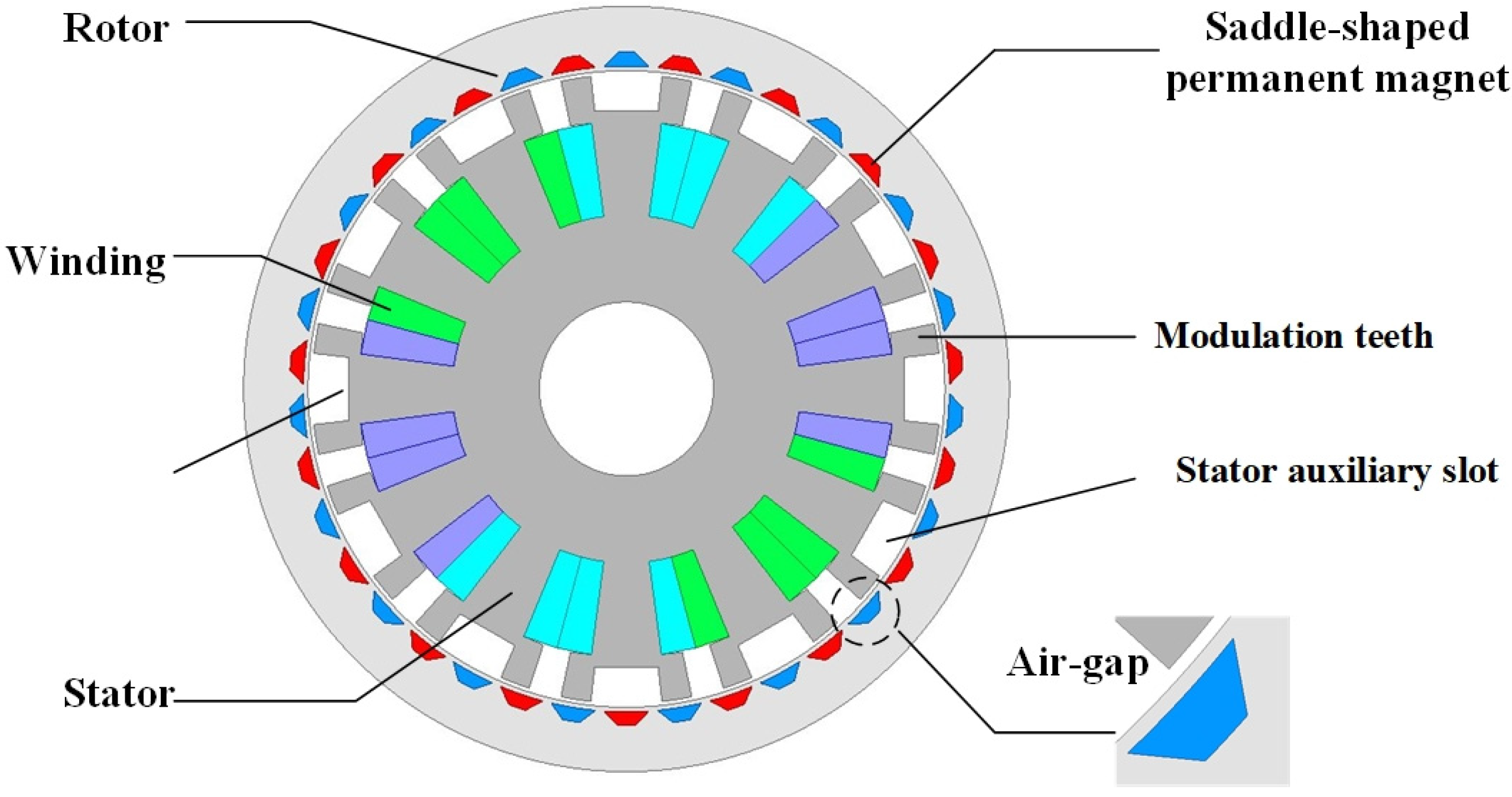
Figure 1. The structure of 2D PMVSM model.
Electronics 12 04341 g001
Figure 2. The spatial–temporal distribution of radial electromagnetic force.
Electronics 12 04341 g002
Figure 3. The spatial–temporal harmonic decomposition of radial electromagnetic force density.
Electronics 12 04341 g003
Figure 4. The vibration and noise of the PMVSM: (a) the vibration displacement; (b) the vibration velocity; (c) the vibration acceleration; (d) sound pressure level of the PMVSM.
Electronics 12 04341 g004
Figure 5. The main components of PMVSM: (a) the chassis of PMVSM; (b) the rotor core of PMVSM; (c) the stator of PMVSM; (d) the rotor integration of PMVSM; (e) the stator end cover; (f) the stator fixed shaft and fastening screws.
Electronics 12 04341 g005
Figure 6. The no-load experiment of the PMVSM: (a) no-load experiment platform; (b) no-load back-EMF comparison between the FEM and experiment.
Electronics 12 04341 g006
Figure 7. The modal experiment of the PMVSM: (a) the modal experiment platform; (b) PMVSM tapping point.
Electronics 12 04341 g007
Figure 8. Frequency response curve.
Electronics 12 04341 g008
Figure 9. The noise experiment of the PMVSM.
Electronics 12 04341 g009
Figure 10. The noise of the PMVSM.
Electronics 12 04341 g010
Table 1. The parameters of the PMVSM.
ItemValueUnit
Diameter of rotor220mm
Diameter of stator180.8mm
Inner diameter of rotor183mm
Inner diameter of stator50mm
Diameter of stator auxiliary slot bottom160.4mm
Air gap length1.1mm
Core length100mm
The depth of SPM10mm
Angle of short side of SPM4°
Angle of long side of SPM8°
Length of VPM13.1mm
Width of VPM3mm
Table 2. The stator modal shape and natural frequency of PMVSM according to the FEM.
ModesModal Shapes and Natural Frequencies
(2, 0)Electronics 12 04341 i001Electronics 12 04341 i002
822.4 Hz838.3 Hz
(2, 1)Electronics 12 04341 i003Electronics 12 04341 i004
1298.7 Hz1331.5 Hz
(3, 0)Electronics 12 04341 i005Electronics 12 04341 i006
2097.8 Hz2156.6 Hz
(3, 1)Electronics 12 04341 i007Electronics 12 04341 i008
2404.4 Hz2491.6 Hz
(4, 0)Electronics 12 04341 i009Electronics 12 04341 i010
3936.1 Hz3988.3 Hz
(4, 1)Electronics 12 04341 i011Electronics 12 04341 i012
4253.5 Hz4310.5 Hz
Table 3. The stator modal shape and natural frequency of PMVSM by experiment.
ModesModal Shapes and Natural Frequencies
(2, 0)
and
(2, 1)
Electronics 12 04341 i013Electronics 12 04341 i014
831 Hz1303.4 Hz
(3, 0)
and
(3, 1)
Electronics 12 04341 i015Electronics 12 04341 i016
2120.2 Hz2477.1 Hz
(4, 0)
and
(4, 1)
Electronics 12 04341 i017Electronics 12 04341 i018
3950.3 Hz4278.3 Hz
Disclaimer/Publisher’s Note: The statements, opinions and data contained in all publications are solely those of the individual author(s) and contributor(s) and not of MDPI and/or the editor(s). MDPI and/or the editor(s) disclaim responsibility for any injury to people or property resulting from any ideas, methods, instructions or products referred to in the content.