1. Introduction
In the last century, the automotive industry predominantly outsourced software development, concentrating its efforts on the mechanical aspects of vehicle design. However, the landscape is rapidly shifting, with software technology emerging as a decisive factor in automotive distinctiveness. Software has emerged as the most significant driver of revenue growth for automotive manufacturers. Consequently, conventional automakers are evolving from their conventional identities, becoming tech-centric entities specializing in automotive software. This transformation can be tangibly observed in numerous automotive manufacturers that have adopted software updates in their vehicles, triggering seismic shifts within the automotive OTA software market. As vehicular hardware evolves to facilitate software updates, the revenue model is experiencing a tectonic shift from an asset-centric to a service-centric paradigm.
Simultaneously, worldwide digital companies such as Amazon Web Services (AWS), Google, Alibaba, and Tencent are poised to expand their footprint in the automotive technology arena. These software-driven enterprises are aggressively embedding vehicles into their ecosystems and are ready to deliver novel vehicle-connected services. The efficacy and functionality of these diverse services depend on the underlying software, similar to the dependence of a smartphone’s capabilities on its operating system. Such vehicles are referred to as software-defined vehicles (SDVs) [
1].
Several automotive components should be electrified to enhance the performance and functionality centered around software [
2]. Successfully commercialized electrified components include parts that interact with the driver, such as steering, transmission, pedal, and other features. These electrified components all adhere to the X-by-wire paradigm, undergoing a transformation from conventional mechanical operations to an electrical signal-based module [
3]. Notably, automotive automatic transmission systems exemplify this transition.
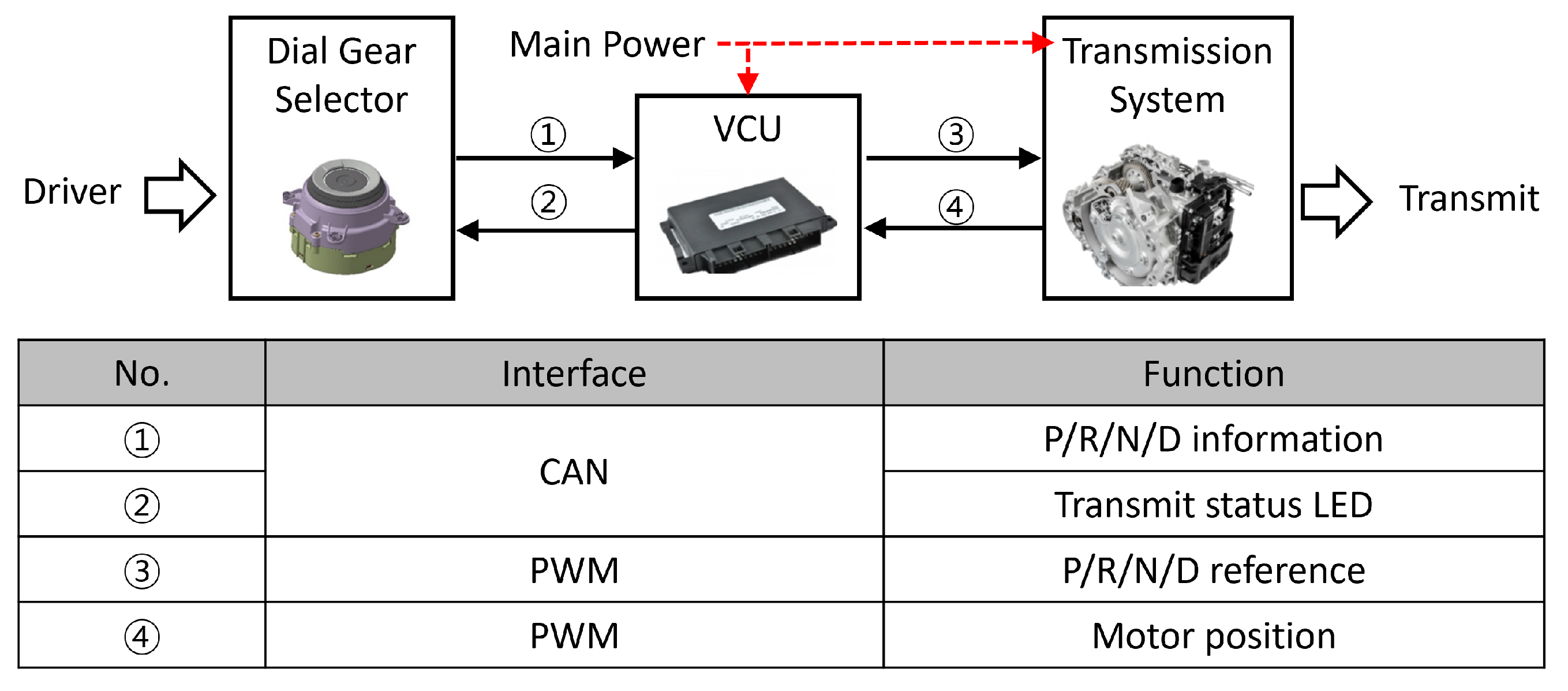
In particular, automatic transmission systems are being altered from mechanical gear shift selectors to electronic systems such as button-, rotary-, and dial-type systems. In automatic transmission systems based on mechanical gear shift selectors, the driver’s manipulation of the selector mechanically alters the automatic transmission’s gears via cables. However, developing fully electrified automatic transmission systems eliminates mechanical cables and physical selectors. Mechanical gear shift selectors have been supplanted by buttons, rotary controls, and dials, transmuting the driver’s input into electrical signals conveyed via a VCU to the automatic transmission.
Applying fully electrified automatic transmission systems engenders several benefits, including heightened vehicle interior design flexibility. Electronic gear shift selectors based on buttons or dials, which replace conventional mechanical gear shift selectors typically adorning the center console, function as design elements and enable the versatile utilization of surrounding spaces. Moreover, these electronic controls facilitate the implementation of driving convenience features such as remote smart parking assistance systems and smart valet parking [
4], tasks hitherto impossible without the driver’s input in conventional mechanical gear lever systems.
A fully electrified automatic transmission system has several advantages, including new functionalities, design adaptability, enhanced user experience, alignment with prevailing trends, and cost-effectiveness for both manufacturers and consumers. However, several considerations should be addressed [
5,
6], most importantly the nominal time delay between the driver manipulating buttons or controls and the execution of the corresponding gear selection within the vehicle. This temporal lag emanates from the time required for the VCU to interpret, process, and transmit the signal of the gear shift selector to the actuator inside the automatic transmission. The time delay in fully electrified automatic transmission systems is typically well under 1 second [
7]. In scenarios necessitating precise vehicle movements within confined spaces, this delay may cause discomfort to the driver. Secondly, the position control performance of the automatic transmission should be guaranteed. Given that the force acting upon the automatic transmission varies depending on the selected gear, the actuator should surmount these forces while maintaining precise positional control [
8]. These issues are unique to fully electrified automatic transmission systems and absent in conventional automatic transmission systems.
The merits of conventional automatic transmission systems lie in their intuitiveness and unwavering reliability. The gear sequence (P–R–N–D) is a universal standard across all automotive models worldwide [
9]. Furthermore, each gear is mechanically linked via cables, ensuring palpable tactile feedback for the driver and real-time recognition of gear changes. Significantly, the position of the gear lever is mechanically determined, ensuring consistent transmission to the transmission and precise gear selection.
Therefore, the electrification of transmission systems necessitates addressing the challenges of minimizing time delays and preserving gear selection accuracy—attributes inherently embedded in conventional transmission systems. Several research groups have developed algorithms for fully electrified automatic transmission systems, including gear shift selectors [
7,
10,
11]. However, these studies focused on the performance improvement inside the automatic transmission system, such as gear shift timing.
This study attempts to augment the responsiveness of the automatic transmission actuator in response to driver-initiated gear selections while concurrently enhancing positional accuracy in the presence of external perturbations. Accordingly, the characteristics of the electric gear shift selector (E-shifter)–VCU–actuator are first analyzed, which are components of the gear shift system, and a shift operation algorithm is designed considering the interface between components to minimize the overall shift time delay. In addition, to improve the position control performance of the automatic transmission actuator, a position control algorithm robust to disturbances generated in the automatic transmission is proposed. Control stability analysis was also performed to prevent malfunctions of the proposed actuator’s position control algorithm. A hardware-in-the-loop simulation (HILS) system was developed using an actual mass-produced dial-type gear shift selector to verify the operation algorithm of the electronic shifting system proposed in this study. The proposed electronic shifting operation algorithm was verified via various driving scenarios based on the HILS.
The remainder of this paper is organized as follows.
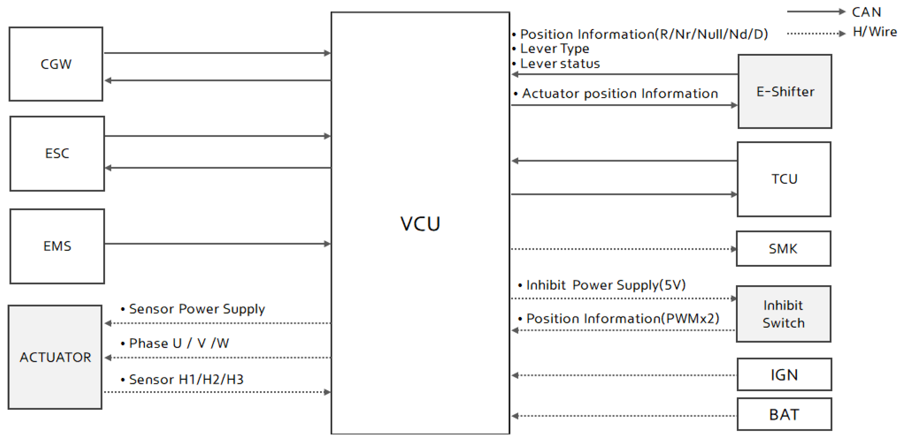
Section 2 comprehensively describes the configuration and electrical interfaces of the automatic transmission systems. In
Section 3, we develop the operational sequence of the actuator for automatic transmission, design a robust position control algorithm that handles external automatic transmission forces, and conduct a control stability analysis. In
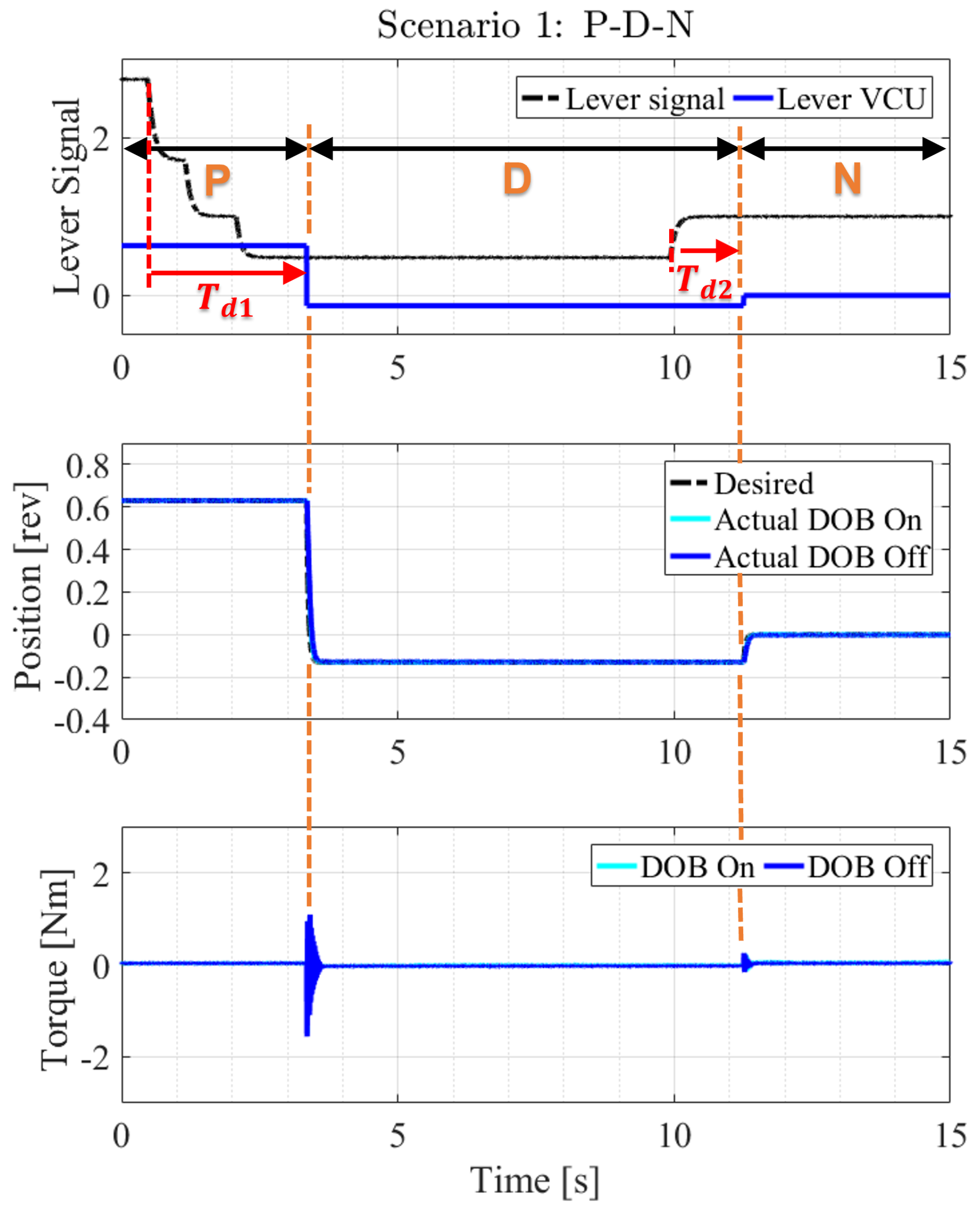
Section 4, we verify the proposed algorithm via an experimental setup and present the results for several driving scenarios.
Section 5 concludes this paper.
3. Control Algorithm for Gear Position in an Automatic Transmission System
In this Section, a comprehensive analysis is presented, elucidating the intricate shifting sequence from the dial selector all the way to the shifting actuator within the automatic transmission. This meticulous examination takes us through the step-by-step process, dissecting the multifaceted mechanics that underlie the gear shifting mechanism. Subsequently, we delve into the development and proposal of a sophisticated control algorithm meticulously designed for the shifting actuator. This algorithm, while seemingly straightforward in theory, stands the test of real-world challenges with resilience, particularly when confronted with issues like inherent friction within the system. The intricate analysis undertaken in this section delves deep into the complexities of overcoming these practical challenges, offering valuable insights into the optimization of the shifting actuator’s performance.
3.1. Gear Shift Process in the Automatic Transmission Using a Dial-Type Gear Selector
For the shifting actuator to move at a predetermined shift angle as intended by the driver, there must be a shift angle corresponding to the rotation angle of the dial-type selector. For example, as shown in
Figure 2a, if the driver rotates the dial to
for the P gear input, the shifting motor should be turned to
, as defined by Equation (
1).
where
represents a proportional factor for
, as indicated in
Table 1.
In addition, because the dial-type selector cannot independently input the desired gear shift, unlike the button type or bar type, the VCU should determine the driver’s intention by observing the staying time on the corresponding gears on the dial-type selector.
Consequently, the VCU measures the time the dial-type selector stays in a specific range (
), as expressed in Equation (
2), to determine the driver’s final shift intention.
3.2. Robust Position Control Based on a Transmission-Disturbance Observer
When the shifting position is determined from the dial, the actuator in the automatic transmission moves to the predefined gear position. The automatic transmission mechanism has a link that presses it with a spring such that the angle is not altered at the preset position. Therefore, the actuator overcomes this spring force and moves over the groove to shift; hence, a robust position control algorithm is required for this actuator.
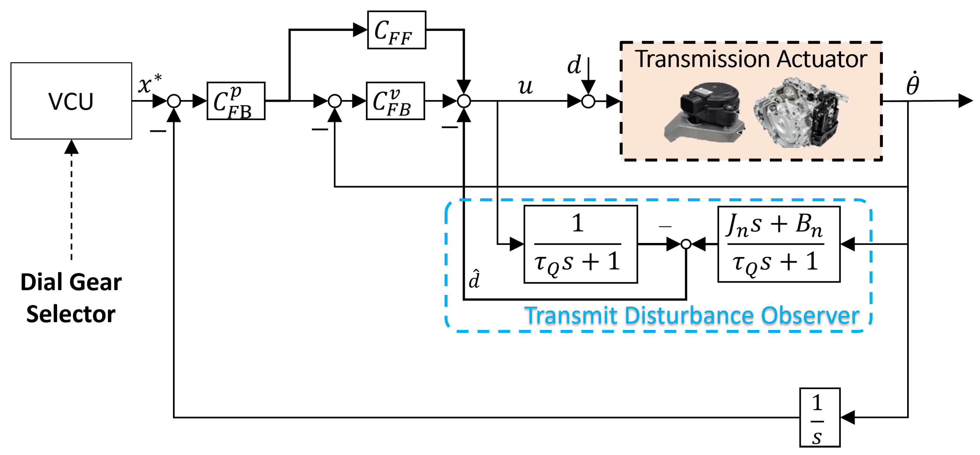
Therefore, we propose a robust position control algorithm for the gearbox, as illustrated in
Figure 4. In the proposed algorithm, all external forces, including the spring force acting on the gearbox during shifting, are assumed to be lumped transmission disturbances.
A disturbance observer (DOB) [
12] is the most effective technique for estimating the disturbance and can also be adopted to suppress the gear transmission disturbance.
In particular, the DOB observes the disturbance acting on the system by utilizing the nominal model of the system and Q filter. The nominal model in this automatic transmission system includes a transmission actuator and a transmit link.
Figure 5 presents the dynamic characteristics of the transmission actuator system using the frequency response from motor torque to the speed. The speed of the actuator can be calculated from the encoder attached to the motor shaft. Considering the dynamic characteristics, the nominal model of the system is assumed to be a first-order dynamic system in the frequency domain and expressed as
where the plant model parameters are assumed to be
and
. Therefore, the estimated lumped disturbance can be calculated using the nominal model (
) and expressed as
where
, which mostly influences the robustness of the DOB system, is designed as a first-order low-pass filter to satisfy the causality in a first-order dynamic system. The cutoff frequency of the filter (
) is set as 13
. Notably, the sensor measurement noise and model uncertainty are not considered in Equation (
3). Hence, the closed-loop transfer function of the automatic transmission system from motor torque to speed is determined as
Therefore, the closed-loop transfer function of the position controller, including the transmission disturbance observer (T-DOB), is derived as
where
denotes the transfer function from • to ∘;
represents the feedback controller of the position control loop, with a transfer function defined as
;
represents the feedback controller of the speed control loop, with a transfer function defined as
; and
represents the feed-forward controller of the speed control loop, with a transfer function defined as
. Because the spring presses the groove to fix the gear link, the frictional force acts differently when the motor moves. Accordingly, the stability of the controller should be satisfied even when the dynamic characteristics of the system are subject to change. The dynamic characteristics that change in the nominal model are expressed as
in
Figure 6a. Then, the actual plant model can be expressed as
The parameter to be changed can be regarded as a
term in (
2) and is assumed to have the following range (
<
<
). By applying this range, the model variation (
) is derived as
To ensure stability, the small-gain theorem [
13] is adopted. According to this theorem, the infinity norm should be less than 1 to guarantee closed-loop stability, expressed as
where
represents the complementary sensitivity function calculated from the block diagram in
Figure 6a and derived as
where
, and
represents the integral operator (
) required to obtain the motor angle from the speed.
Figure 6b demonstrates that
is the inverse of
and that the stability of the closed-loop system is guaranteed in the overall frequency. Model parameter
varies within the range of
. The parameters of each controller are set as follows:
,
,
, and
.


