Article

Coupling between Cavity Resonances and Characteristic Modes on Household Appliances

1
Department Electronic Engineering and Communications, I3A, University of Zaragoza, 50009 Zaragoza, Spain
2
Department R&D Induction EMC Laboratory, BSH Electrodomésticos España S.A., 50016 Zaragoza, Spain
*
Authors to whom correspondence should be addressed.
Electronics 2023, 12(21), 4484; https://doi.org/10.3390/electronics12214484
Submission received: 31 July 2023 / Revised: 25 October 2023 / Accepted: 29 October 2023 / Published: 31 October 2023

Abstract

:
Home appliances generally comprise a mechanical envelope, or enclosure, of electrically conductive material (steel, aluminum, etc.) that houses electrical and electronic circuits. That envelope typically includes all kind of apertures, openings, holes, slots, windows, etc., to connect—physically and electromagnetically—the external space with its internal space. The performance of that envelope is a key element to comply with surface current EMI/EMC (Electro-Magnetic Interference/Electro-Magnetic Compatibility) regulations for electromagnetic interference, both emissions and immunity. Here, we present a novel theoretical proposal that consists of establishing the mathematical relationship of the coupling between the resonant modes of an internal cavity (RMs) contained in a conductive body and the characteristic modes (CMs) on the external surface of its envelope through the openings that connect those external and internal spaces, and doing so by means of equivalent virtual surface currents located in those openings. The comparative results of simulations and actual measurements of immunity in an anechoic chamber (measurements originally oriented to other purposes) are presented as above-mentioned evidence of resonating modes coupling on the frequency range 40–1000 MHz. However, this theoretical proposal is novel and remains to be developed in greater depth and detail in future works.

1. Introduction

As a result of strict electromagnetic compatibility (EMI/EMC) regulations, all electronic devices must undergo thorough radiated emission and immunity tests for electromagnetic interference before being launched in the market.
Normally, an enclosure made of conductive material serves to give mechanical support to the equipment. It also isolates or shields the electromagnetic activity of the electronic circuits inside from all the electromagnetic activity that takes place in its outside environment. In this way, two spaces or regions delimited by this envelope or enclosure can be defined, the internal cavity (inner space) of the equipment and the external environment (outer space).
In the inner space, the walls of the cavity impose boundary conditions to the electromagnetic fields (EM fields) that influence the configuration of these fields and give rise to resonant modes (RMs) in the cavity.
In the outer space, the external EM fields find the envelope as a typical dispersion element and cause on its external surface a distribution of currents that can be broken down into characteristic modes (CMs), as proposed by the Theory of Characteristic Modes (TMC).
Both spaces, the inner (cavity) and the outer ones, are coupled through the inescapable apertures of the envelope. The general problem of coupling through apertures has many specific applications [1,2,3,4,5].
The mechanical envelope of a home appliance, a commercial induction hob, is used as an illustrative basis for a novel theoretical proposal. It analyzes the coupling between both resonances or modes, which are the resonance modes (RMs) of the electromagnetic cavity formed by said mechanical envelope with apertures, and the characteristic modes (CMs) of the surface electric currents that circulate outside the envelope.
Butler et.al. [2] reviews the methods available to address the classic problem of penetration of electromagnetic fields inside a conductive body with apertures. Usually, the concept of equivalent magnetic surface currents located in the apertures is used to propose a model with the short-circuited apertures and equations to be solved that require compliance with the boundary conditions in those apertures.
Harrington and Mautz [3] proposed another modal analysis, the theory of characteristic modes, for problems consisting of two regions coupled by an aperture. The modes, derived from a weighted “eigen” equation provide a set of expansion functions of the equivalent magnetic surface currents at the aperture.
Leviatan [4] conducted a more specific study of the same subject. In this case, the dimensions of the aperture were electrically small, known as the Rayleigh region, or equivalently, the working frequency was very low. This study resulted in a new set of expansion functions for the equivalent magnetic surface currents in the aperture.
El Hajj et al. [6] also carried out a specific study in the case of an electromagnetic cavity with apertures that flow into a semi-infinite space that carries a plane wave as an incident field in the apertures. The subsequent modal analysis, which considers the resonant modes of the cavity, results in a new set of expansion functions (characteristic modes) of the equivalent magnetic surface currents in the apertures.
Ladbury et al. [7] demonstrate the complexity of relating the signal present in a cavity with apertures to external electromagnetic radiation. They also comment on the usefulness of supporting the analysis with statistical methods to address a general system that does not depend on overly specific details.
Gradoni et al. [8], partly based on Ladbury’s article [7], propose a statistical model of coupling of electromagnetic radiation with the interior of a cavity with apertures. This type of study has been carried out since the mid-2000s. In their conclusions, they emphasize that the signal coupled through an aperture shows power peaks in the resonance frequencies of the aperture itself. Furthermore, when there is a cavity behind the aperture, new power peaks appear at the frequencies of the resonance modes (RMs) of the cavity.
Kwon et al. [9] address the problem that the resonances of an aperture practiced in a conductor enclosure of finite dimensions are coupled with the natural resonances of the cavity, ostensibly worsening the shielding capacity of the envelope (measured according to the typical parameter SE—Shielding Effectiveness). Apart from demonstrating the effect through numerical results, he proposes as an attenuating factor of the problem to install dielectric bodies with losses in the cavity that reduce its Q-factor.
Araneo and Lovat [10] address a system like the one in this article in which a conductive body with an aperture of finite thickness envelops an electromagnetic cavity. The system is irradiated with an external electromagnetic plane wave and the way to solve the distribution of EM fields both inside, in the aperture and outside the body, is to create three regions that are separated from each other by equivalent magnetic surface currents according to the equivalence principle. To solve each region, the corresponding Green’s functions are used, which, except for very simple cases, involve a strong numerical calculation.
Guang-Tsai [11] proposes a simple and efficient method to solve Green’s function for a cavity and accelerate its numerical calculation.
Liang and Cheng [12] perform a meaningful analysis of the electromagnetic coupling of an incident plane wave in a slot aperture backed by a lossy rectangular cavity. His formulation of a generalized network based on the principle of equivalence led him to replace the apertures with equivalent magnetic surface currents and to look for resonances in the cavity and the penetration of electromagnetic power into the cavity. This analysis is close to the proposal of our article, except for contemplating the CMs on the outside of the cavity.
Bailin, Ma and Cheng [13] addressed the coupling of the EM fields of an incident wave with a lossy cavity through a slot aperture opening, although in their case they used the equivalence between a “slot” and a conductive wire.
In their comprehensive study, researchers have addressed the classic coupling problem between electromagnetic fields present inside a finite conductive cavity with apertures and an electromagnetic field (EM field) radiating from the outside. They have considered various factors, including the resonant modes of the cavity (RMs), the resonant modes of the aperture itself, excitation of the aperture by an external radiant field, the application of statistical methods, and the analysis of equivalent magnetic surface currents, among others.
Here, a novelty is proposed: a study on a finite conductive body that contains an electromagnetic cavity and a study of the coupling between the characteristic modes (CMs) of the external surface, calculated according to the TCM, and the resonant modes (RMs) of the cavity through the apertures practiced in the body. Apertures are mathematically replaced by equivalent magnetic surface currents that will guarantee the continuity of the EM fields present in them. Once the coupling has been demonstrated, the control of the CMs would have an influence on the RMs within the cavity and, therefore, on the effectiveness of the shielding of the body.
In a Section 1, the mathematical theory is presented including a brief review of both resonance theories and a proposal for the coupling between them. For the resonant modes (RMs) theory, the envelope is considered an electromagnetic cavity. For the characteristic modes (CMs) theory, the induced currents on the surface of a conductive body are considered. Finally, a proposal to combine both theories is presented to understand the coupling between both resonant modes.
In a Section 2, a simulation model has been developed to estimate the RM and CM resonances of the envelope of a commercial home appliance, an induction cooker. The enclosure is emptied of its internal components exclusively to facilitate the estimation and measurement of the natural resonances of the envelope.
In a Section 3, laboratory measurements carried out in semi-anechoic chamber (SAC) provide evidence of the coupling between RMs and CMs, supporting the main purpose of this article. During the laboratory tests, the appliance under test (DUT) has been irradiated with an electromagnetic plane wave inside a semi-anechoic chamber (SAC) and measurements have been taken of the electric field strength inside the DUT.
The final study suggests that external radiation excites certain characteristic modes CMs on the surface that, in turn, excite the resonant modes RMs of the cavity. The corroboration of the coupling between both resonant modes provides valuable insight into the potential utility of the Theory of Characteristic Modes (TCM). This understanding can contribute to finding solutions for electromagnetic EMI/EMC compatibility issues.

2. Materials and Methods

2.1. Theoretical Analysis

There is a long tradition in the development of modal analysis for various types of electromagnetism problems. Any modal analysis gives results that are independent of the excitation of the system, as in:
  • Waveguide modal analysis
  • Cavity modal analysis (RMs)
  • Characteristic modes analysis (CMs)

2.1.1. Waveguide Modal Analysis

This modal analysis studies the transmission of energy in long waveguides [14] (pp. 351–482) [15]. This technique of modal expansion deals with the electromagnetic field propagation within an enclosed conductive structure dictated by the boundary conditions (BCs) imposed by the waveguide’s cross-sectional profile (Figure 1).

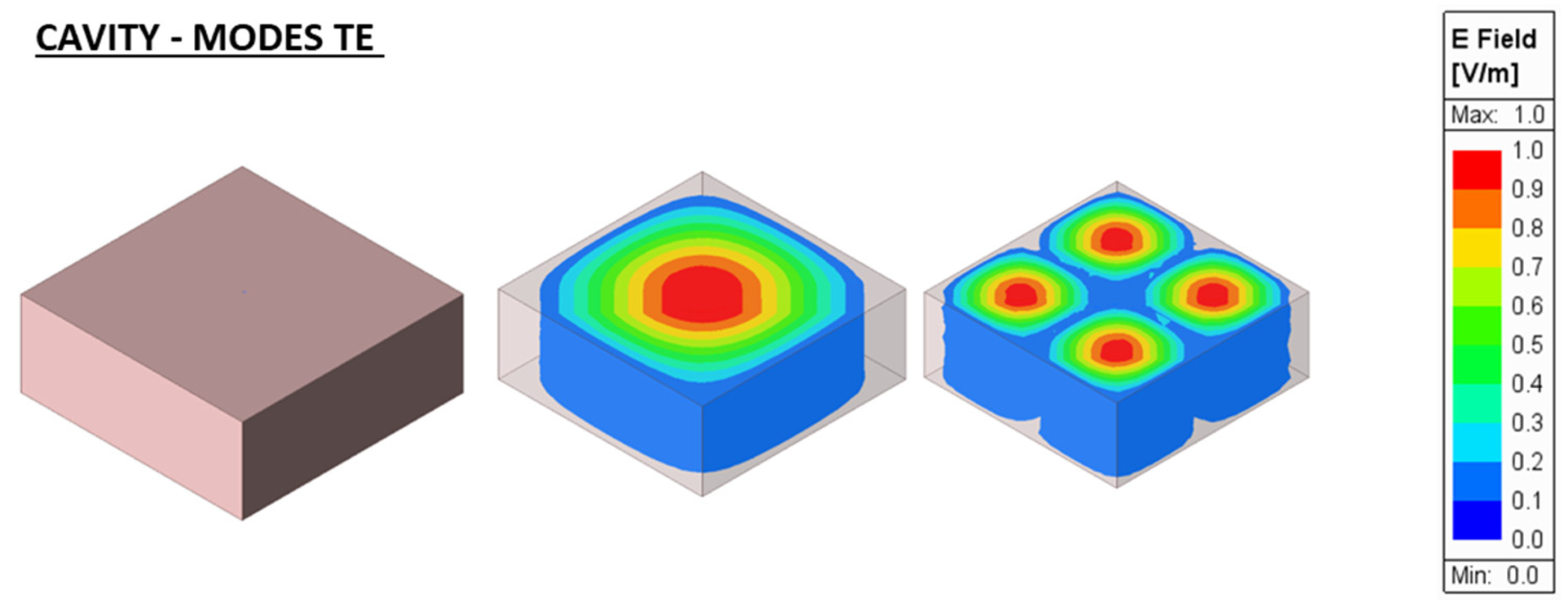
2.1.2. Cavity Modal Analysis RMs

The modal analysis in cavities [14] (pp. 351–482) [15] works with the configurations of the electric and magnetic fields within a rectangular cavity and RMs can be classified as transversal TE or TM modes and are obtained in a similar way to those in a waveguide (Figure 2).

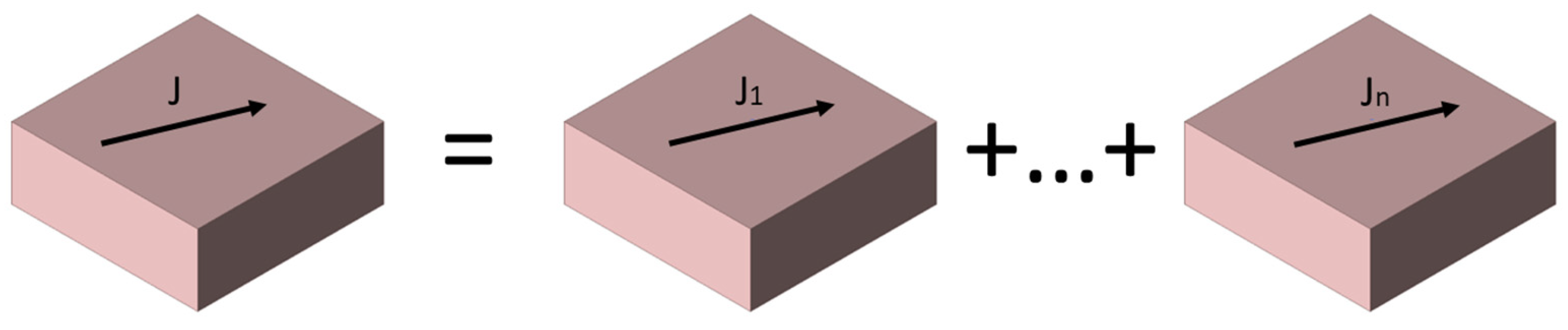
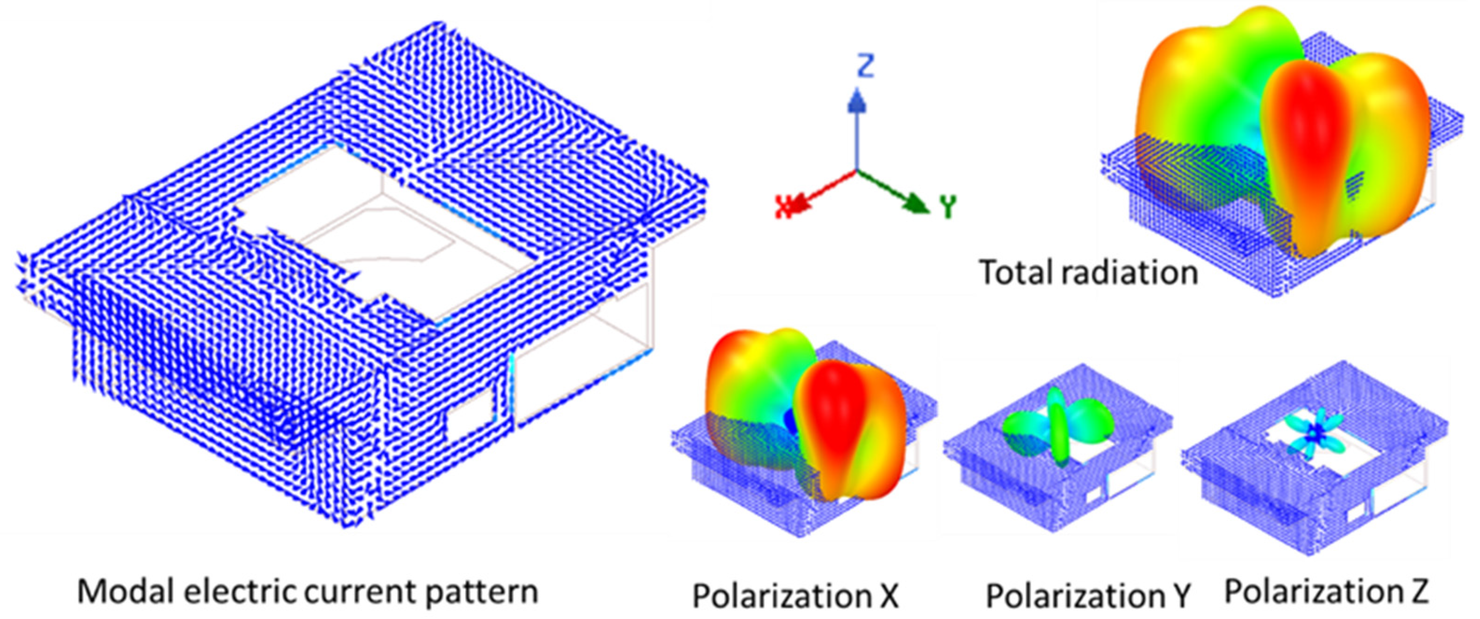
2.1.3. Characteristic Modal Analysis CMs

The modal analysis method based on the Theory of Characteristic Modes (TCM), also known as Characteristic Modes Analysis (CMA), decomposes the induced electric surface currents circulating over a finite and electrically conductive body into composing basis surface currents known as “characteristic modes” CMs (Figure 3).
The total surface current can be broken down as a combination of “characteristic modal” surface currents:
J = n A n J n
where:
  • J is the total electric surface current on the surface of a conductive body.
  • Jn is the modal electric surface currents composing the total electric surface current.
  • An is the modal excitation coefficient.
This modal analysis arises from the first studies from Garbacz [16], Harrington and Mautz [17], Inagaki and Garbacz [18], Chen [19] and others.
Initially conceived for perfectly electrically conducting (PEC) structures delimited by an outer surface, the TCM exhibits these key characteristics:
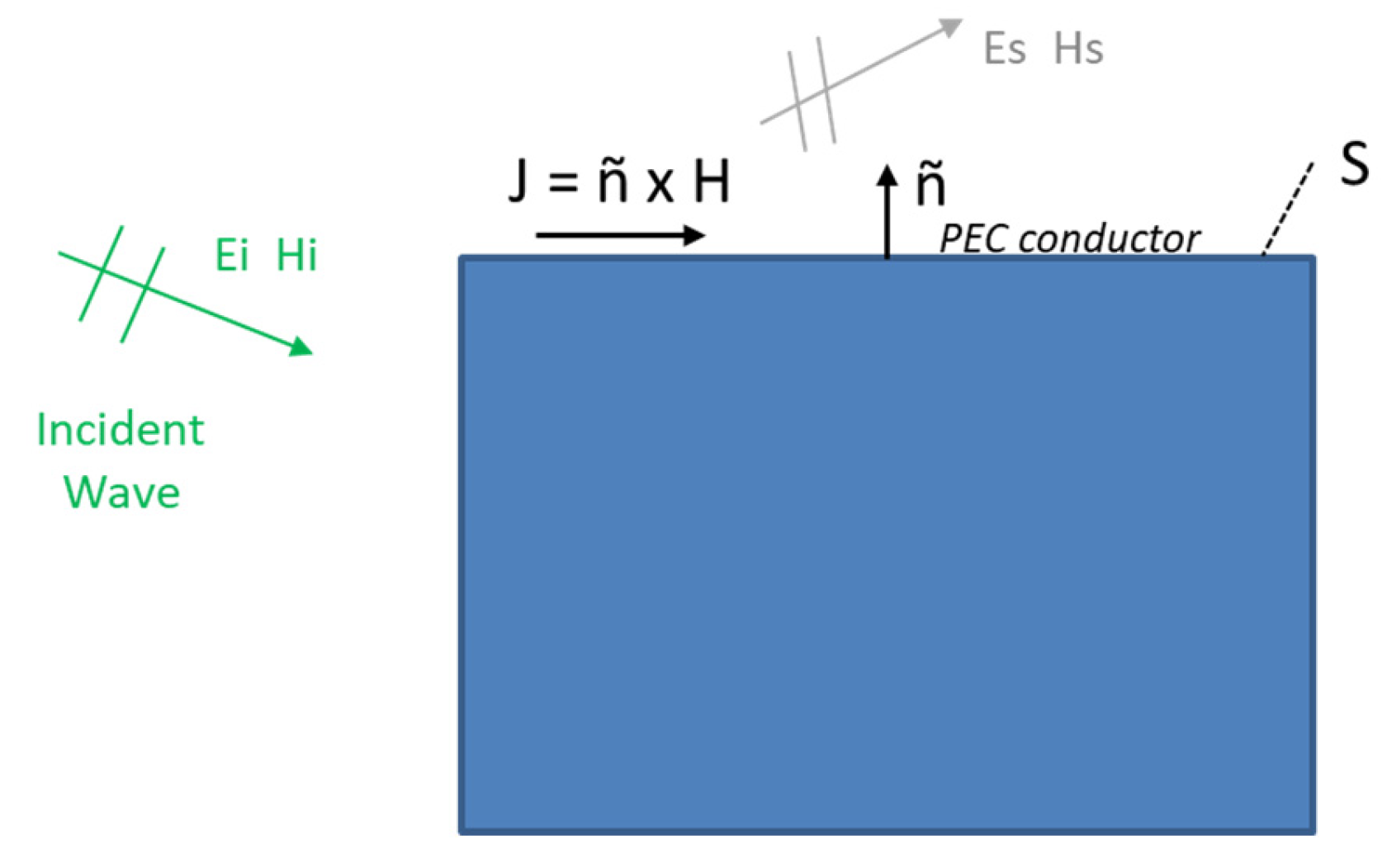
  • Any PEC body delimited by an open or closed surface (S) is associated with an eventually infinite set of real modal characteristic surface currents (Jn).
  • Each modal surface current (Jn) radiates a characteristic electric field (En) into the free space.
  • The tangential component of (En) on (S) is equiphasic.
  • There is a “characteristic angle” (90–270°) defining the phase lag between (Jn) and tangent component of (En) and associated with each CM.
  • The orthogonality of (Jn) over (S) as well as the orthogonality of (En) with respect to the radiation sphere at infinity enables CMs to function as a valuable basis set in expanding any potential surface currents and fields associated with the conductive structure.
Normally TCM is developed from the Electric Field Integral Equation (EFIE) which reveals the relationship between the electric fields and the surface currents. It can also be formulated from the Magnetic Field Integral Equation (MFIE). The Method of Moments (MoM) [20] is then applied to discretize the EFIE, or MFIE, into matrix equations [19] (pp. 43–58) [21].
An incident plane wave (Ei, Hi) induces surface currents (J) on the electrical perfect conductor (PEC) body which in turn produce a scattering field (Es, Hs) (Figure 4).
The solution of the field scattered by the surface electric currents, caused by the incident field, must comply with Equation (2), just as any solution of Maxwell’s equations must comply with the boundary conditions (BC).
[Ei + Es]tan = 0 on surface S
The tangential component of the scattered electric field, generated by surface electric currents, can be expressed by an integro-differential operator L( ).
L(J) = −Es on surface S
where L(J) expresses the electric field generated by the surface electric current density J. The operator in Equation (3) has impedance dimensions, and it is expressed according to this notation:
Z(J) = [L(J)]tan
In this way, the basic equation to be solved is as follows:
Z(J) = [Ei]tan
Applying the “Method of Moments” to solve the integro-differential Equation (6), and using expansion functions of type RWG [19], a solution is obtained in the form of equations that can be express as a matrix:
[Zij] [Jj] = [Vi]
where [Zij] is the discretized form of the impedance operator Z( ). As this operator is symmetric due to the reciprocity theorem but not strictly Hermitian, it can then be split into its Hermitian parts giving rise to the linear operators R( ) and X( ).
Z = R + jX = [½ (Z + Z*)] + [1/(2j) (Z − Z*)]
Let us use the following weighted eigenvalue equation based on the impedance operator Z( ) and its Hermitian parts.
Z(Jn) = R(Jn) + jX(Jn) = νn W Jn = (1 + jλn) W Jn
Choosing W = R as the weighting function, expressing νn = 1 + jλn, and eliminating the common term appearing on both sides of the equation, results in the generalized eigenvalue equation that exhibits the essential modal properties of a system governed by an eigenvalue equation.
X Jn = λn R Jn
where Jn is the eigenvector that defines the modal electric surface currents, or characteristic modes (CMs).
“Modal significance” (MS) is an expression based on eigenvalues λn that is an inherent property of each mode and that quantifies the coupling strength, or resonance, of each CM with external sources. Used with the modal excitation coefficient (An), it gauges the extent to which each mode contributes to the overall electromagnetic response to a particular source:
MS = |1/(1 + j λn)| MS ∈ [0, 1]
Relevant modes are defined as those that comply with:
M S 1 2 = 0.7071   Significant   or   relevant   CM

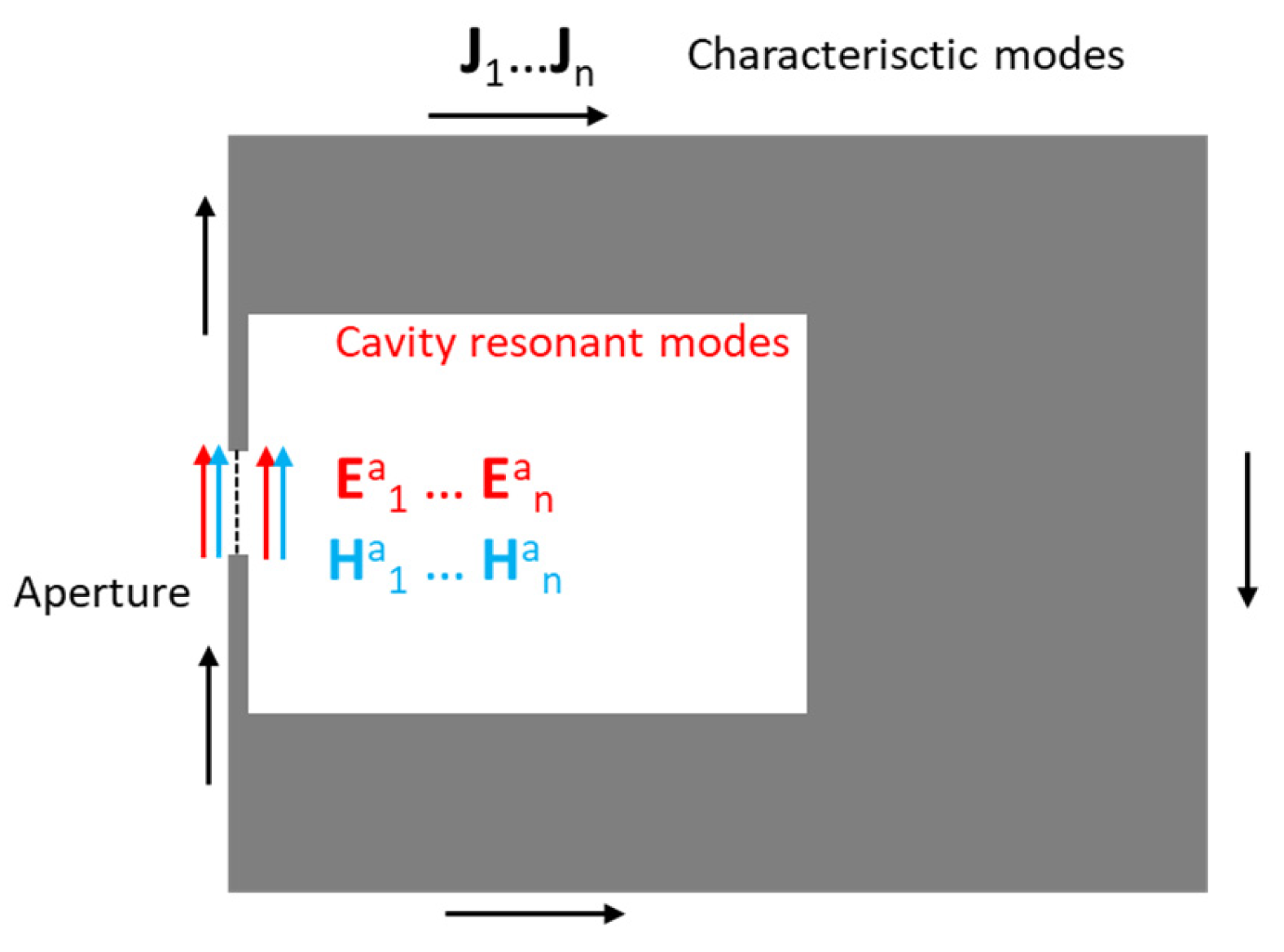
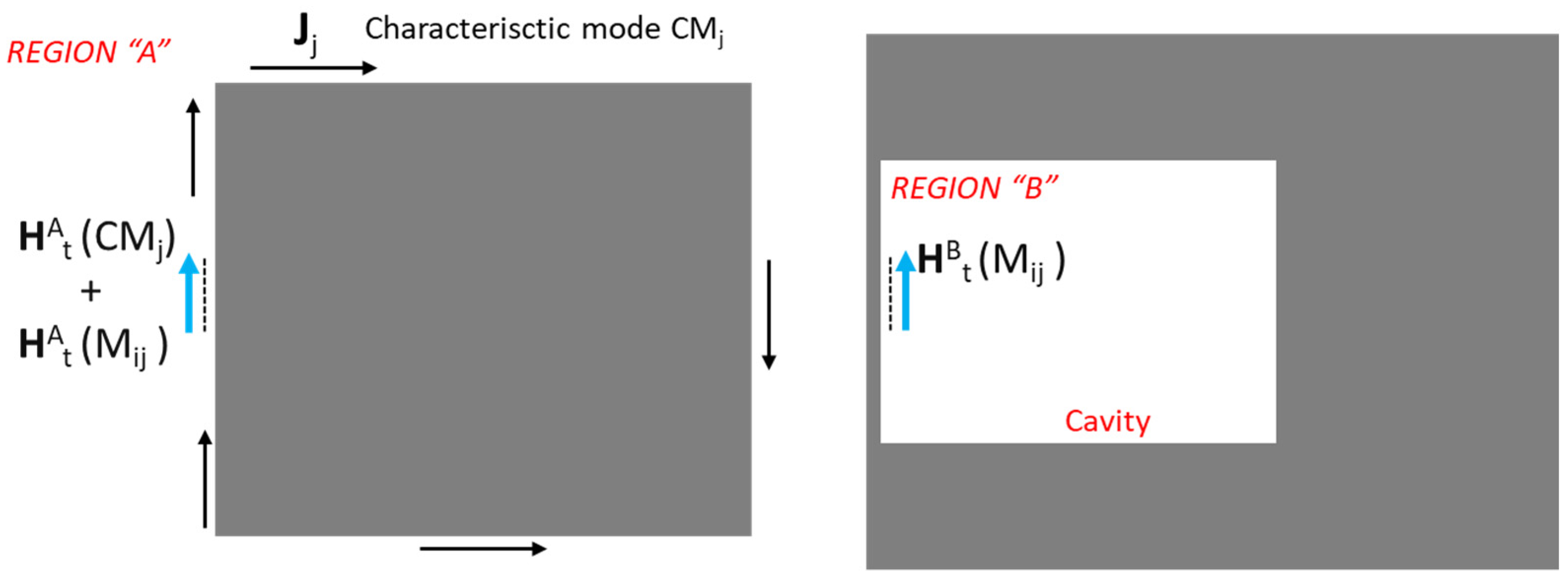
2.1.4. Two Separated Spaces

The main objective of this work is to apply the modal analysis of “characteristic modes” (CMs) to the outer surface of the envelope and the modal analysis of the “resonant modes” (RMs) to the cavity. Then, the existing apertures in the envelope are analyzed as a coupling of both spaces and both resonant modes (Figure 5).
At the end, an incident EM field (Ei, Hi) excites the characteristic modes of the outer surface; then, the induced currents on this surface generate EM fields in the aperture which, in turn, excites the interior space of the equipment, causing the resonances in the cavity. Both resonances, the exterior and the interior ones, are coupled by the fields present in the aperture. For each CM (Jn), an electric field (Ean) and a magnetic field (Han) are generated at the aperture, as shown in Figure 6.
The equivalent surface theorem [14,22] allows for the creation of a model that mathematically separates the two spaces, the external and the internal ones, incorporating equivalent virtual surface currents (electric Jan and magnetic Man) which guarantees the continuity of the EM fields at the apertures for each one of them. Figure 7 shows the external space provided with the equivalent electric and magnetic surface currents at the aperture.
Then, the whole cavity is replaced with a perfectly conductive solid material (PEC) and only the equivalent magnetic surface currents for each CM are applied thanks to the uniqueness theorem [14,22] (Figure 8).
Likewise, in the case of the internal space (cavity), the equivalent surface theorem [14,22] allows for the incorporation of equivalent virtual surface currents (electric Jan and magnetic Man) which guarantees the continuity of the EM fields at the apertures for each one of them (Figure 9).
Again, the outer space is replaced with a conductive material (PEC) (uniqueness theorem [14,22]) and only the equivalent magnetic surface currents must be applied (Figure 10).

2.1.5. Coupling between RMs and CMs

So, the application of the equivalence and uniqueness theorems has separated the problem into two parts, external space (region A) versus internal space (region B), the cavity, as shown in Figure 11.
Both spaces are coupled through the aperture and their characteristics can be expressed by aperture admittance matrices [1].
From the modal analysis of the cavity, with the apertures covered by conductive material, the list of resonant modes RMs, whose frequency is within the range of interest, and their associated modal configuration of EM fields is obtained (Figure 12):
Cavity resonant frequencies = FCi i = 1,… N
FCN < Fmax Range of frequencies of interest.
At each one of the RMs frequencies, and studying the corresponding CMs, a list of relevant CMs is obtained (in general, modal significance MS > 0.70 approximately as indicated before).
Significant CMs at FCi: CMj (FCi) j = 1…M(i)
The equivalent magnetic surface currents in the aperture ensure that the tangential component of electric field (Eat) is continuous across the aperture. The remaining condition that must be implemented is the continuity of the tangential magnetic field component (Hat) throughout the aperture (Figure 13).
HAt (CMj) + HA (Mij) = HBt (Mij)
Mij = Mj (FCi)
where:
  • HAt (CMj)—Transverse magnetic field on outside region “A” due to j-th “characteristic mode” CMj
  • Mij—Equivalent magnetic surface current at aperture due to j-th “characteristic mode” CMj at the i-th resonant frequency FCi of the cavity
  • FCi—Frequency of i-th resonant mode RM of the cavity
  • HAt (Mij)—Transverse magnetic field on outside region “A” due to equivalent magnetic surface current on aperture Mij
  • HBt (Mij)—Transverse magnetic field on cavity inside region “B” due to equivalent magnetic surface current on aperture Mij
The use of the method of moments [21] is proposed to obtain an approximate solution. A base of fixed, or variable, “expansion functions” must be selected, as well as convenient weighting functions, and the scalar coefficients Vijn are to be determined:
Mij = ∑ Vijn ∗ Mijn
where:
  • Mijn—Expansion functions at j-th “characteristic mode” CMj and at i-th resonant frequency FCi of the cavity.
  • Vijn—Scalar coefficient of linear combination
In addition, a “scalar product < , > applicable at the aperture area, is defined as follows:
< A, B > = ∫a (A B*) dS
Finally, “weighting functions” W are defined that may or may not coincide with the “expansion functions”:
{Wijk} k = 1, 2,…, K Weighting functions
All these elements are applied in such a way that the main condition of continuity of transverse component of magnetic field in the aperture is met:
HAt (CMj) + HA (Mij) = HBt (Mij)
HAt (CMj) = HBt (Mij) − HA (Mij)
HAt (CMj) = ∑(Vijn ∗ HBt(Mijn)) − ∑(Vijn ∗ HA (Mijn))
The Vijn coefficients can be put out of the operator due to the linearity of the Ht( ) operator and applying the scalar product of each weighting function to the equation yields the following system of equations:
<Wk, HAt (CMj)> = <Wk, ∑(Vijn ∗ HBt (Mijn))> − <Wk, ∑(Vijn ∗ HA (Mijn))>
Which, thanks to the linearity of the scalar product, can also be expressed as:
<Wk, HAt (CMj)> = ∑Vijn <Wk, HBt (Mijn)> −∑Vijn <Wk, HA (Mijn)>
This system of equations, which can be expressed and treated in matrix form, allows us to solve with conventional algebraic methods the unknown coefficients Vijn and, therefore, the surface currents Mij by Equation (12). After solving the magnetic surface currents Mij, standard methods can be utilized to calculate the final fields and parameters that are related to the field.
This new mathematical proposal on how to approach the coupling between internal and external fields of a finite conductive body with apertures needs to be explored and finished with concrete examples that demonstrate its feasibility and usefulness.
The idea behind the proposal is to be able to control or affect in some way the EMI/EMC performance of the equipment by studying and altering the CMs that are generated on the outside of the surface of the body.
Perhaps there are examples with simple geometric configurations that can be solved analytically, but it is more likely that numerical simulations allow us to see the consequences of coupling, and that they should be corroborated by real measurements, such as far-field measurements in anechoic chambers.
To illustrate this possibility, below is a real case of tests carried out in an anechoic chamber with an equipment consisting of the envelope of a commercial hob, devoid of its internal electrical and mechanical components, to see the relationship between the CMs that appear on the surface when irradiating with a plane wave and the peaks of electric field strength that appear inside and that would correspond to two RMs. The tests are accompanied by previous estimates by simulation.

2.2. Simulation Analysis of the System

The novel theoretical proposal of coupling between the external CMs and the internal RMs of the cavity are explored with a practical example based on the empty conductive enclosure of a commercial hob that presents several apertures. From this enclosure, a simulation model is created that will serve to estimate the RMs of the cavity and the CMs of the outer surface and the relationship between them, that is, CMs and RMs that are coincident in frequency and that suppose a strong coupling between both will be sought (Figure 14).
The simulation model is implemented with software HFSS version 2022 by ANSYS [23].

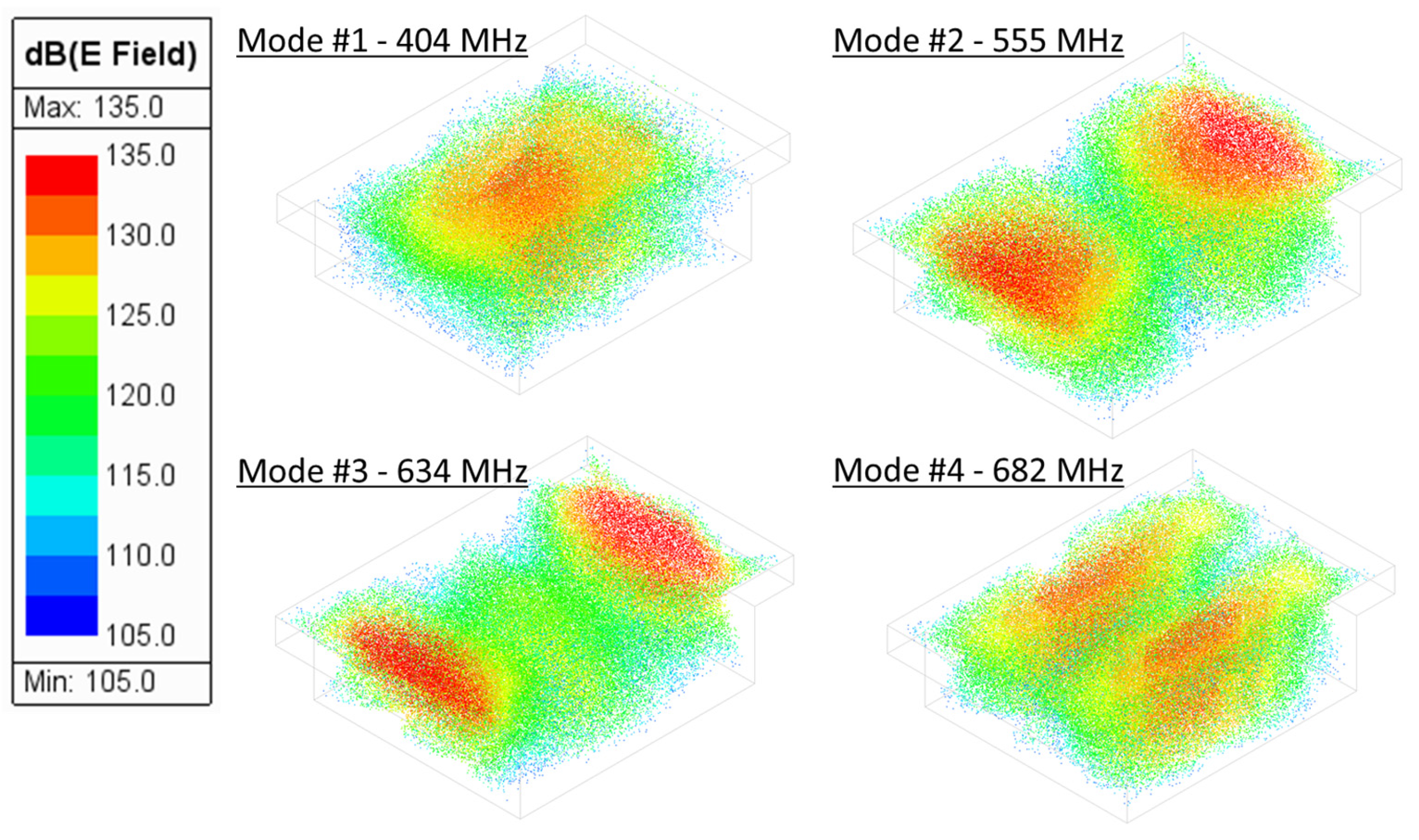
2.2.1. Resonant “Internal” Cavity Modes

The simulator numerically solves the mathematical equations involved (Maxwell’s equations and boundary conditions) and calculates a list of RMs in the frequency range of interest (80–1000 MHz) as shown in Table 1.
The simulator gives a list of seventeen RMs with their configuration of EM fields and some of them are illustrated in Figure 15, in which the antinodes, the zones of maximum electric field strength that characterize each RM, are appreciated.

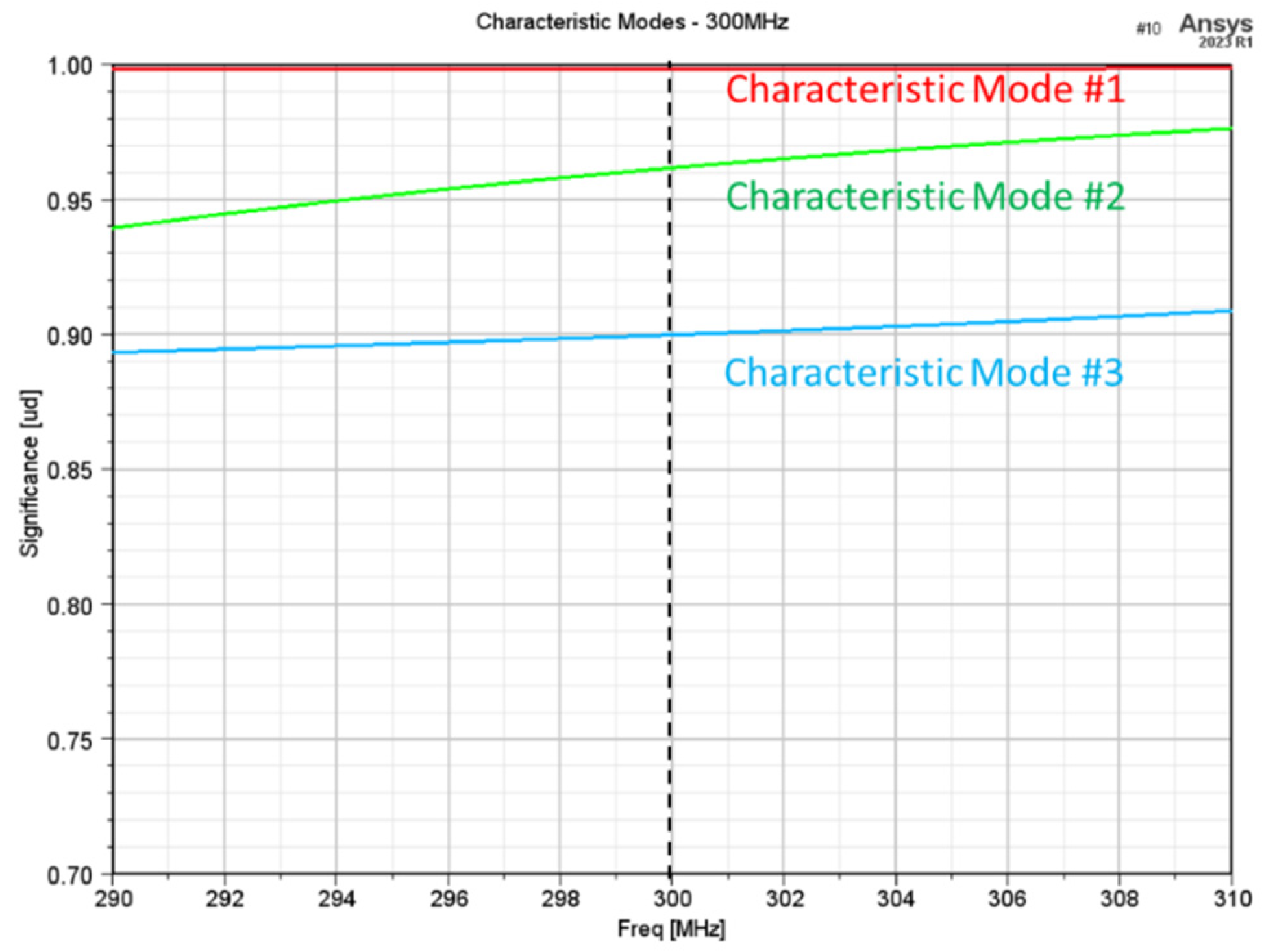
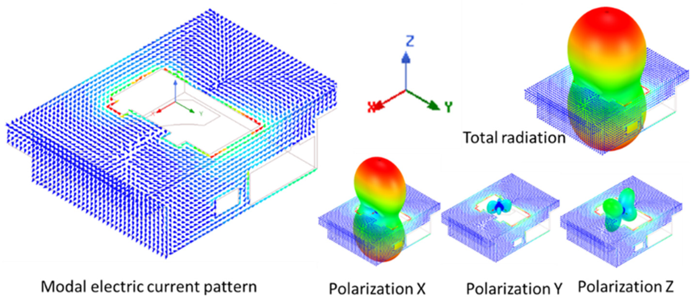
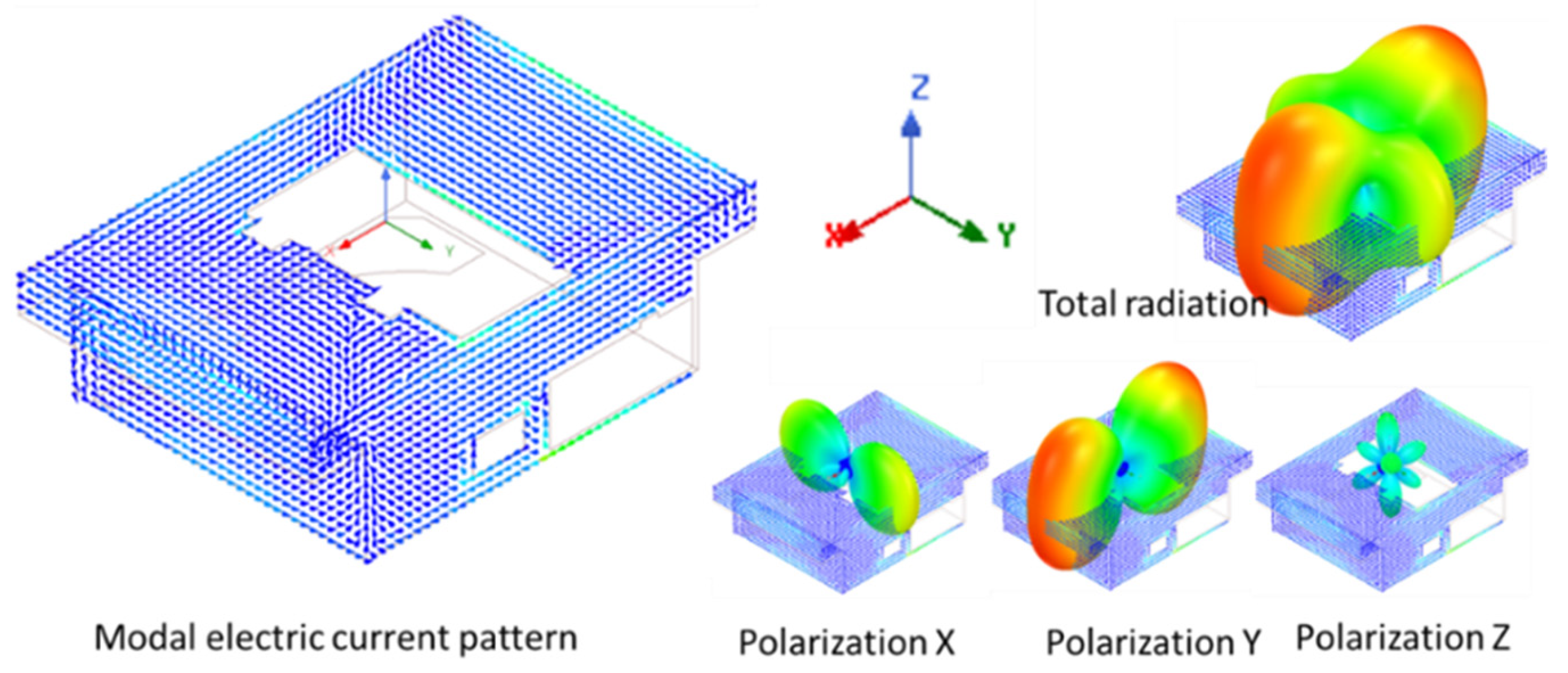
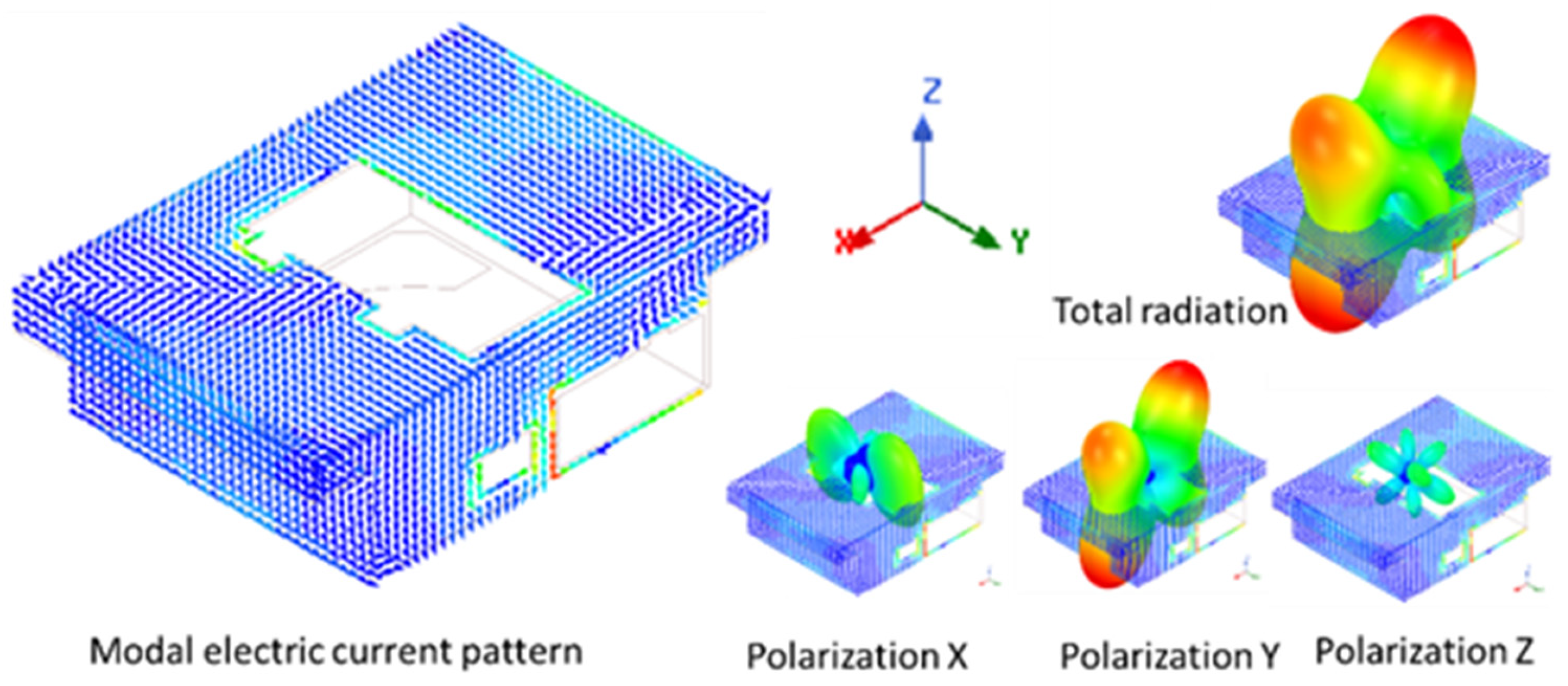
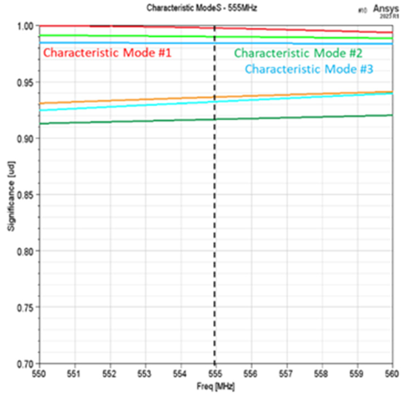
2.2.2. Characteristics “External” Modes

By simulation, the list of the most relevant CMs is extracted for each of the frequencies corresponding to the RMs obtained in the previous section (Section 2.2.1). These “modal surface currents” that make up the total electrical current on the external surface of the hob form an orthogonal basis both in terms of surface currents and in terms of radiation patterns associated with each of them, as stated in the theoretical analysis Section 2.1.3.
The following sections show the relevant CMs for each RM.

2.2.3. Resonant Mode RM#0 at 300 MHz

A cavity RM has not been detected at the 300 MHz frequency, but a CM modal analysis has been conducted anyway as a reference case, which produce three characteristic modes with significance MS above 0.90, as shown in Figure 16. EM field penetration at this frequency will be later studied.
Characteristic modes CM#1 and CM#2 at RM# 0–300 MHz and their radiation patterns are shown in Figure 17 and Figure 18 in which the color red indicates maximum values of surface current density and radiation intensity.

2.2.4. Resonant Mode RM#1 at 404 MHz

At RM#1 (404 MHz), there are six relevant CMs with MS above 0.70 (Figure 19). The first two modes (CM#1, CM#2) are the most relevant, with MS > 0.95. They are studied in detail later, and: the simulator’s characteristic mode tracking method shows that both are swapped at 409 MHz:
Characteristic modes CM#1 and CM#2 at RM#1 (404 MHz) and their radiation patterns are shown in Figure 20 and Figure 21, in which the color red indicates maximum values of surface current density and radiation intensity.

2.2.5. Resonant Mode RM#2 at 555 MHz

At the frequency of RM#2 (555 MHz), there are six relevant CMs with a very easy to excite significance MS above 0.90 (Figure 22). The modes CM#1, CM#2, and CM#3 are the most relevant, with MS > 0.95.
Characteristic modes CM#1 and CM#2 at RM#2 (555 MHz) and their radiation patterns are shown in Figure 23 and Figure 24, in which the color red indicates maximum values of surface current density and radiation intensity.

2.3. Measurements in Anechoic Chamber

Finally, by means of measurements carried out in an anechoic chamber, there remains a question of whether the results obtained in the simulation correspond to reality. To resolve this, the enclosure of the real equipment (DUT) with which the virtual model used in the simulation was designed is introduced into an anechoic chamber, irradiated with plane waves from various directions and polarizations, and the electric field that appears inside the envelope is measured at preselected points by a calibrated electric field probe.

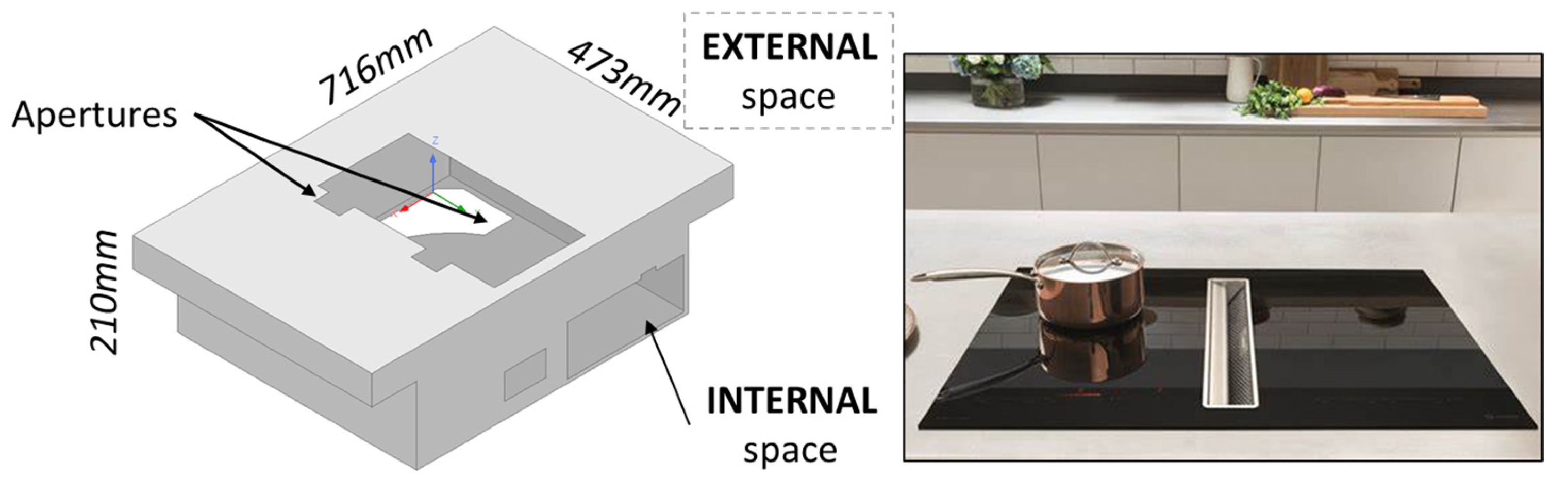
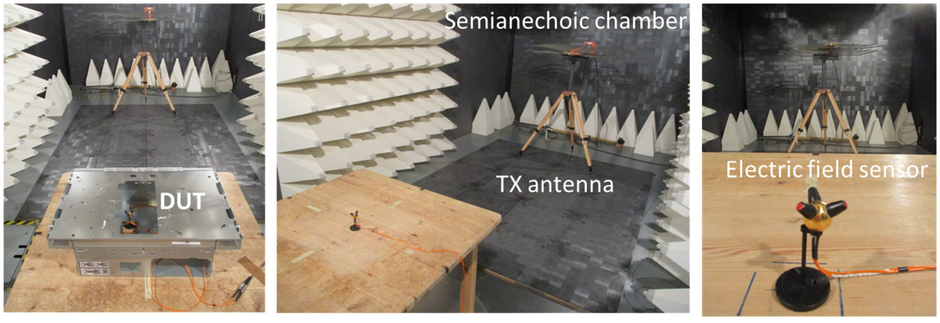
2.3.1. Setup Description

DUT was evaluated experimentally to confirm the theoretical and simulation results. It was irradiated in the frequency range of interest inside of a semi-anechoic chamber (SAC) measuring the electric field inside of the enclosure to corroborate the previous analysis.
For the laboratory, the following main elements were used (Figure 25):
  • Semi-anechoic radiofrequency chamber (SAC).
  • Metal enclosure of a commercial hob, empty of components (DUT)
  • Log-periodic antenna for the 80 MHz–1000 MHz range in vertical and horizontal polarizations powered with 46 dBm.
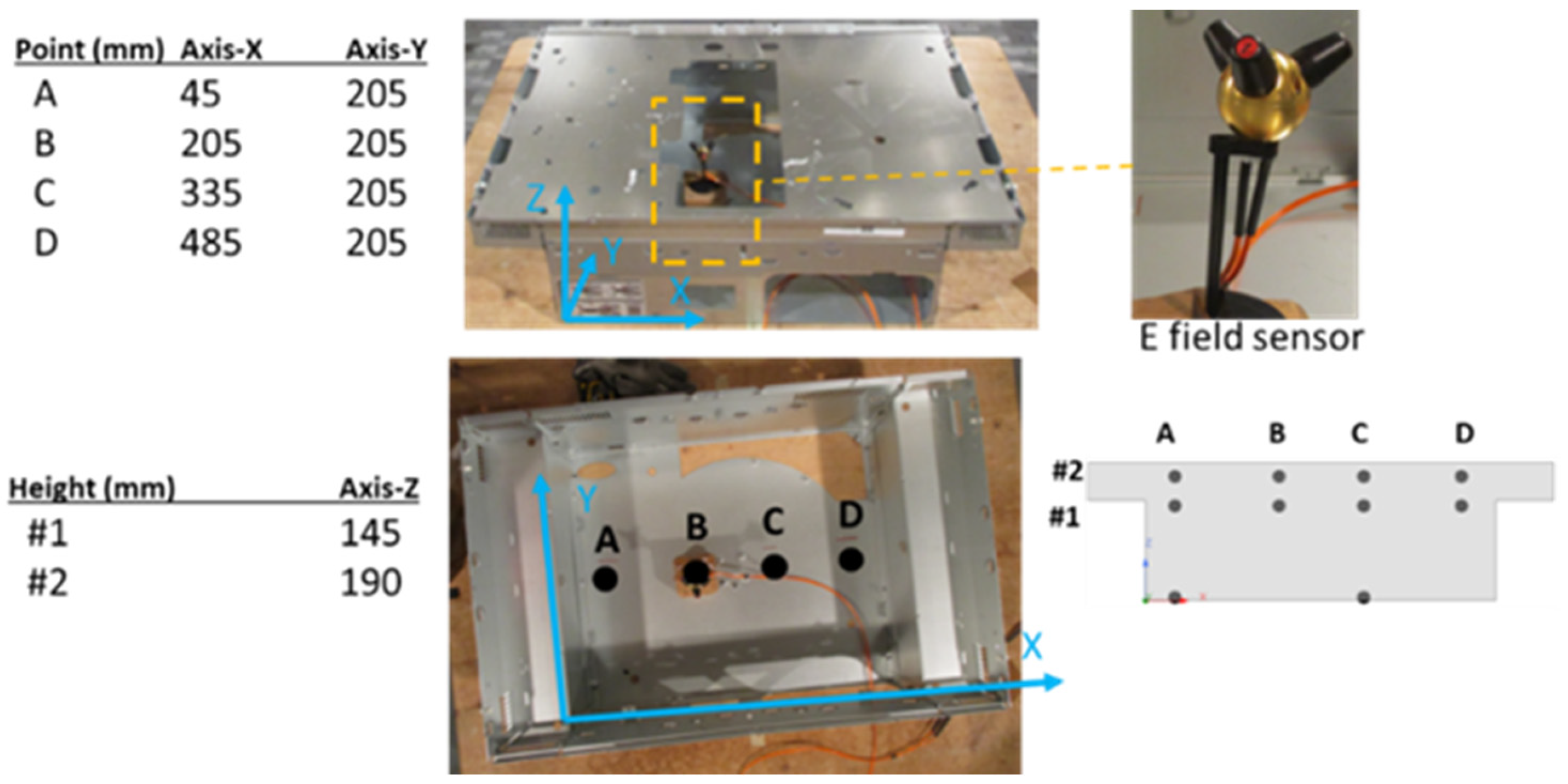
  • A calibrated electric field probe (E field sensor).
A set of electric field measurement points were selected inside of DUT to detect resonances. The measurement points are spread over two heights (height #1 at Z = 145 mm, height #2 at Z = 190 mm), both near the highest part of the DUT and therefore close to the largest aperture of the envelope (DUT). At each height (#1, #2) there are four measurement points (A, B, C, D) that extend from one edge of the envelope to the opposite, thus occupying both points close to border (A, D) and in the center of the internal space (B, C) (Figure 26).

2.3.2. Reference System

The reference used for the measurements is (Figure 27):
  • Radiation direction: yellow dot line (Y-axis)
  • Polarization of the radiated field: vertical (Z-axis)/horizontal (X-axis)

3. Results

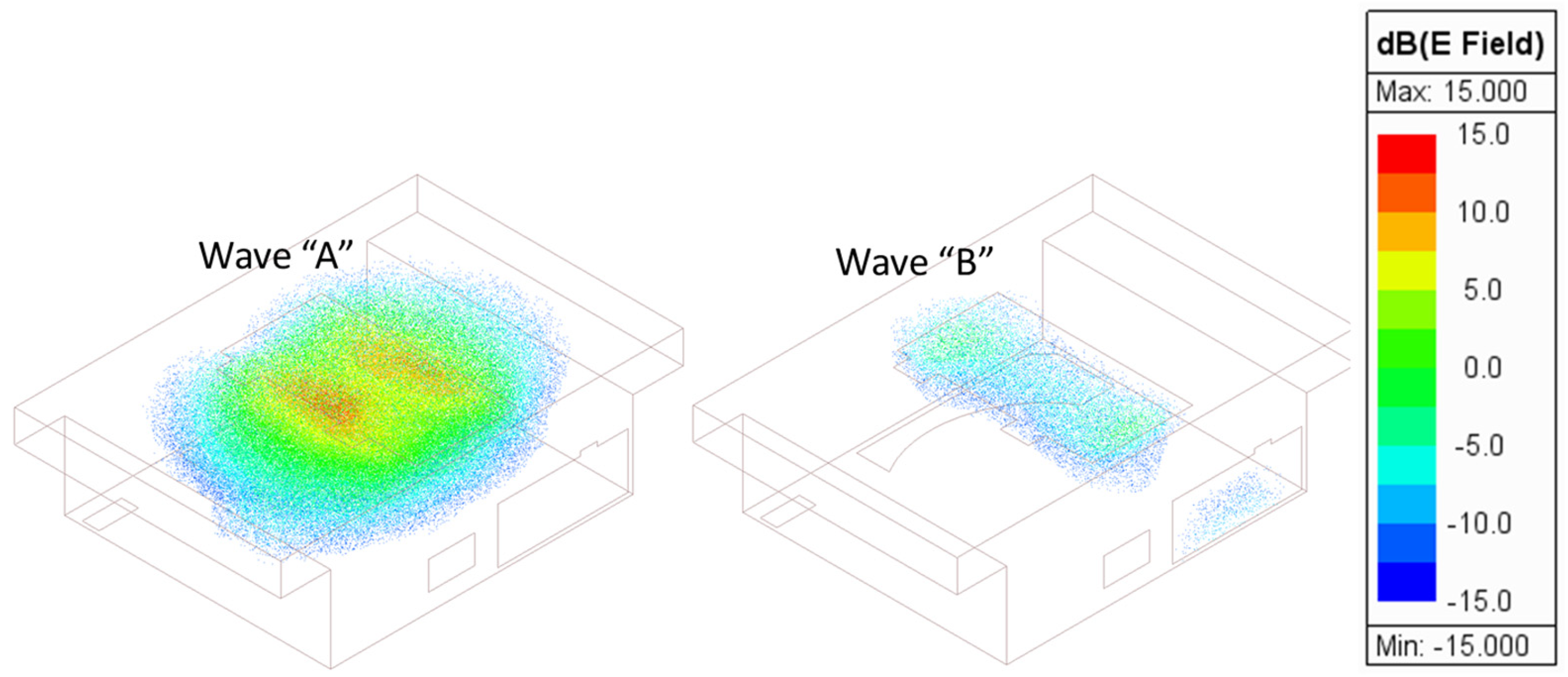
3.1. Simulation Plane Wave Irradiation

The simulation model is irradiated with plane waves of multiple polarizations (Figure 28), “Wave-A” and “Wave-B”, to verify the correlation between both types of modal analysis: the excitation of a CM produces the excitation of a cavity RM:
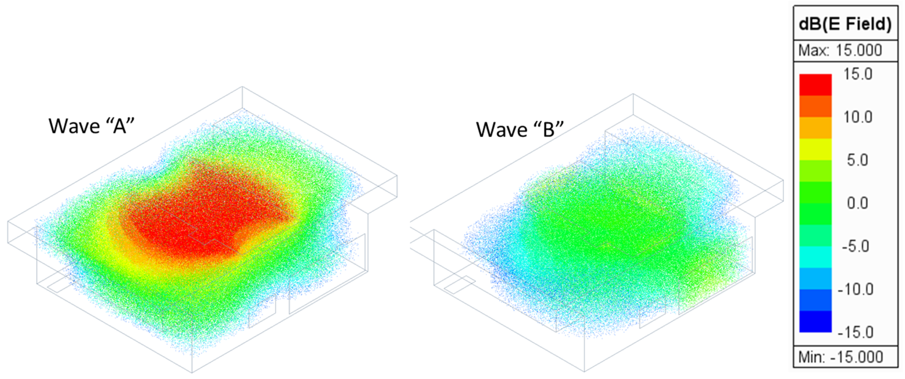
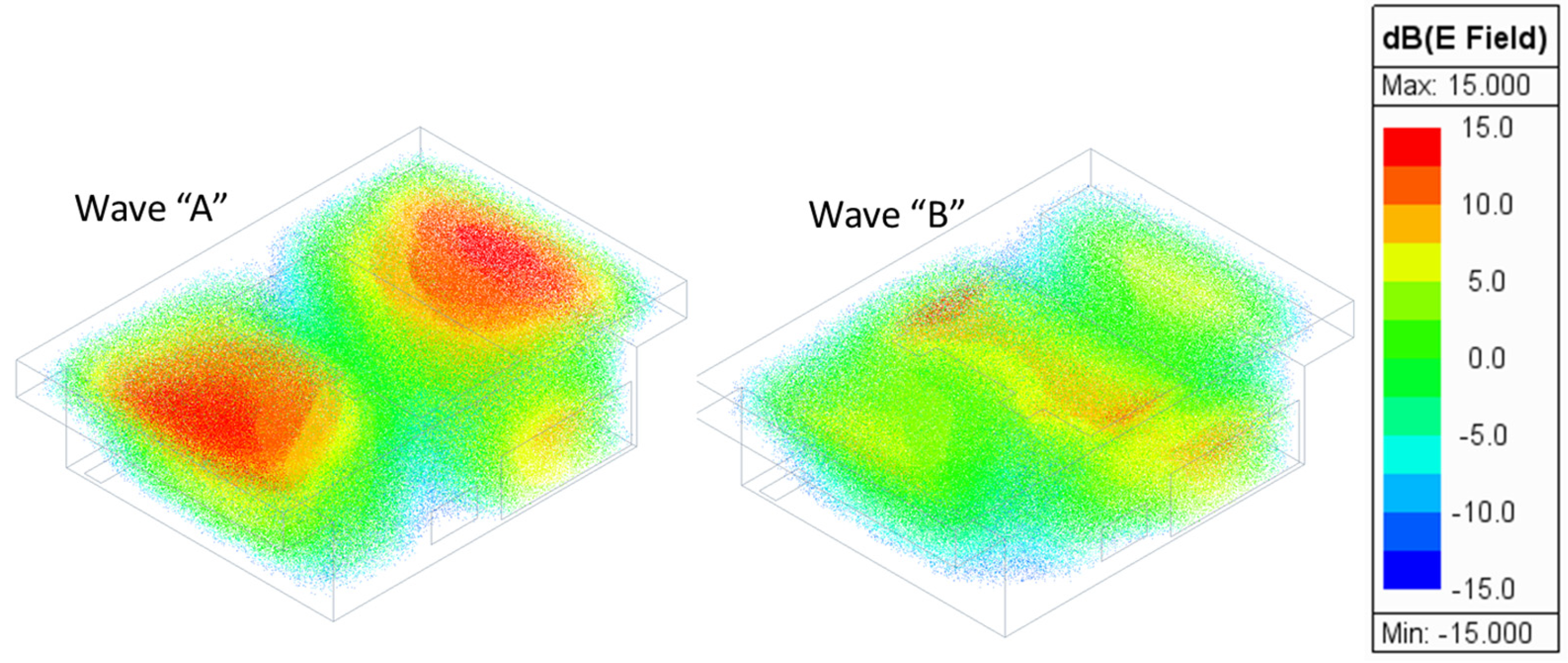
  • “Wave-A” → Vertical polarization (X-axis) → Electric field 1 V/m
  • “Wave-B” → Vertical polarization (Y-axis) → Electric field 1 V/m
Note the scale showed in following illustrations is constant and the center of scale (0 dB) corresponds to wave electric field strength 1 V/m.

3.1.1. Plane Wave at 300 MHz–Reference Case

Although there is no RM at this frequency, 300 MHz is used as a “reference case”. The simulation shows that there is a slight penetration of electric field under Wave-A because of the CM#1 at 300 MHz with high significance (MS = 1), although this CM #1 cannot be related to any RM at this frequency while Wave-B is not able to significantly penetrate the enclosure (Figure 29).

3.1.2. Plane Wave at 404 MHz

The simulation has proven the existence of a RM at 404 MHz. The EM field penetration (Figure 27) is much higher than at the reference case at 300 MHz (Figure 30) and the distribution of the electric field characteristic is very similar to that of RM #1 at 404 MHz in both cases of irradiation, Wave-A and Wave-B, but mainly in the first case (Wave-A).

3.1.3. Plane Wave at 555 MHz

Again, EM field penetration is much higher in this case (Figure 28) than at the reference case of 300 MHz (Figure 31). The distribution of the electric field highly resembles that of the electric field distribution of RM#2 at 555 MHz with the appearance of two antinodes, zones of maximum electric field at both ends of the equipment, and more intensity in the case of Wave-A.

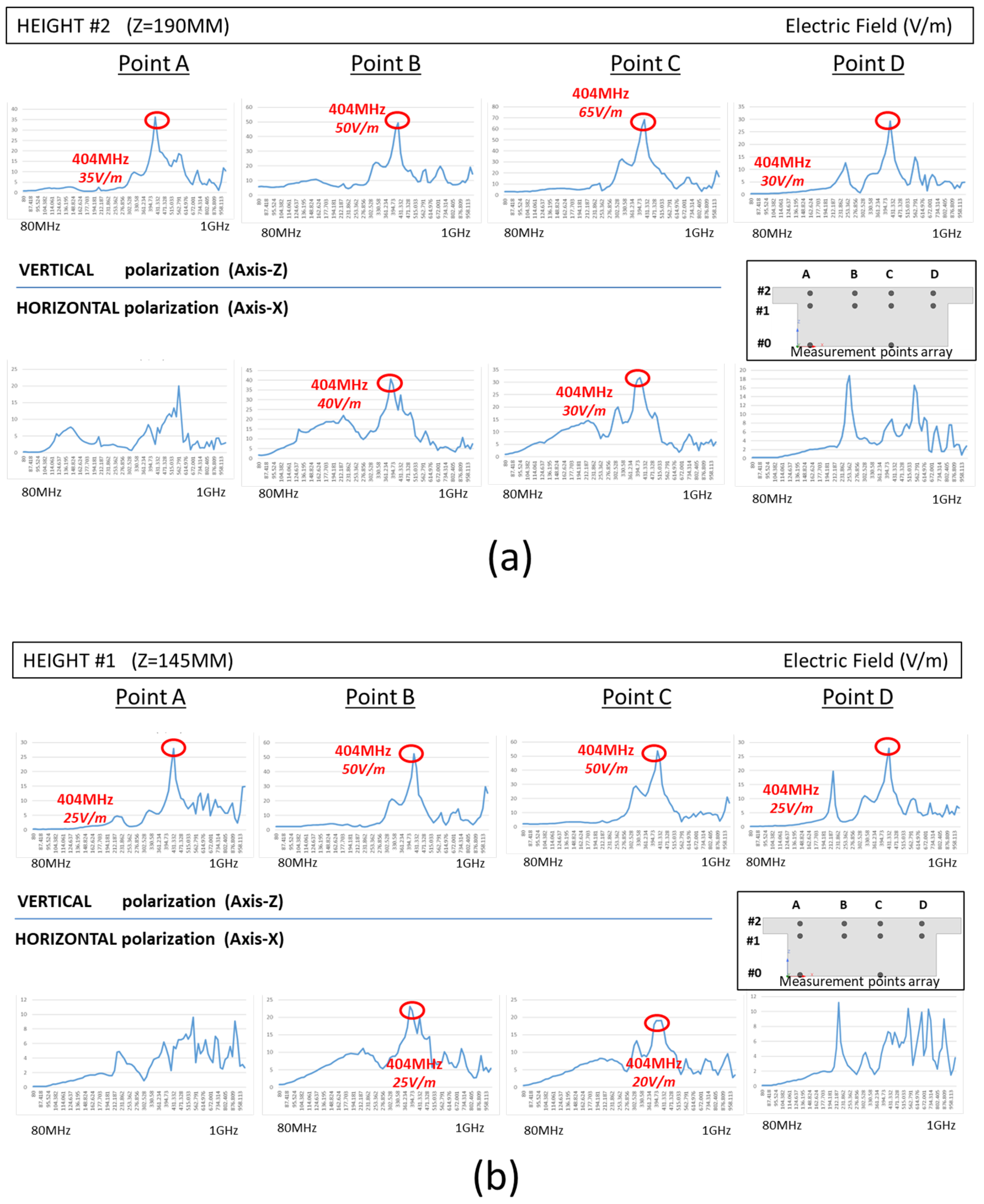
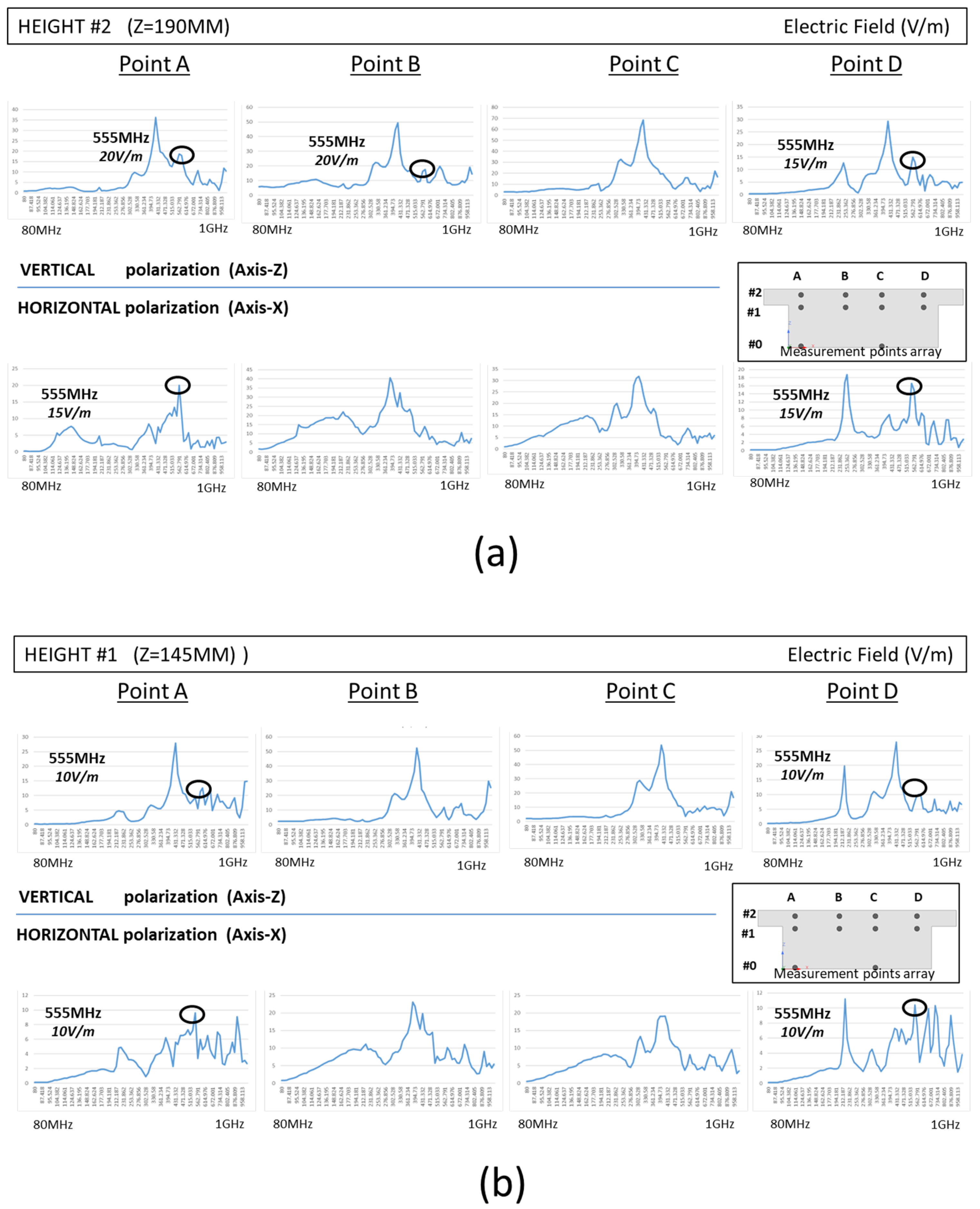
3.2. Real Anechoic Chamber Measurement

The results presented in this paper are a subset of the measurements taken in the actual experiment, whose goals were broader than those presented here. However, these partial results presented are interesting when it comes to drawing conclusions regarding the theoretical proposal of this article. Reference to points of measurement as indicated in “Section 2.3.1—Setup Description”.
  • RM #1-RESONANCE MODE AT 404 MHZ
Figure 32 clearly shows that there is a peak electric field strength at the frequency of 404 MHz, which coincides with the frequency of RM #1 discussed earlier in the simulation section (Section 2.2.4). In addition, and as predicted by the simulation (Section 3.1.2), the peak intensity is higher for vertical polarization (Wave-A) and horizontal polarization (Wave-B). Finally, it should be noted that the profile of the peak electric field strength corresponds to the simulated electric field pattern, with a maximum value in the center of the cavity (Height #2 and Height #1, Points B and C) for both polarizations (Figure 32).
  • RM #2-RESONANCE MODE AT 555 MHZ
Figure 33 clearly shows that there are peaks of electric field strength at the frequency of 555 MHz, which coincide with the frequency of RM #2 discussed earlier in the simulation section (Section 2.2.5). In addition, and as predicted by the simulation (Section 3.1.3), the maximum intensity is higher for vertical polarization (Wave-A) than for horizontal polarization (Wave-B). Finally, it should be noted that the profile of the electric field strength peaks corresponds to the simulated electric field pattern, with two maximum values on the sides of the cavity (Height #2 and Height #1, Points A and D) for both polarizations (Figure 33).

4. Discussion

In this paper, a theoretical novelty is presented which studies the coupling between resonant modes of a hollow conductive body that houses an internal cavity connected to the external conductor surface of the body by means of apertures of negligible thickness.
On the one hand, the outer surface of the body is a physical support for the well-known characteristic modes (CMs) of the Characteristic Mode Theory (TCM) and, on the other hand, the internal space supports the also known resonant modes (RMs) of an electromagnetic cavity.
The proposal consists of separating the total space of the system into two subspaces or regions: the external space of the body bounded by the outer surface of the body and the internal space of the body in the form of a cavity.
Both regions would be separated in a watertight way by the openings of the body that are replaced by perfectly conductive (PEC) walls and by virtual magnetic surface currents according to the principle of equivalence [12] (pp. 328–332), surface currents that remain unknown in the process.
Both regions are studied separately to then compare the characteristics of their respective resonances and mathematically analyze the coupling between them after eventually solving the value of the magnetic surface currents.
Despite the numerous existing studies in the fields of resonance (CM, RM, and other modal analyses), resonator coupling, studies on EMI/CME, etc., the authors have not been able to find any study that contemplates the proposal presented here.
Underlying this proposal is the possibility that an external excitation activates a CM which, in turn, activates an RM inside, impairing the EMI/EMC shielding of the body with respect to its internal space.
In addition, an internal excitation can activate an internal RM which, in turn, excites an external CM that radiates energy, again impairing the EMI/EMC shielding of the envelope.
Confirmation of this proposal could lead to future studies in which controlling the electrical and mechanical design of a system can reduce the coupling between resonant, CM and RM modes, and help improve the EMI/EMC performance of the system.
As an indication or evidence of the theoretical proposal, but not as definitive proof, in this article, a comparative analysis of a real model of the envelope of a commercial home appliance, a hob, with the help of a virtual simulation model and measurements made in an anechoic chamber is added.
The analysis has been carried out in the frequency range (80–1000 MHz), the main objective of the real measurements in anechoic chamber and from which these partial results have been extracted.
The results obtained both in simulation and in real anechoic chamber measurements show a positive correlation between “external” and “internal” MRIs, which may be an indication of coupling between resonators.
At the lowest resonant frequencies (404 MHz and 555 MHz), both types of resonance were compared.
In the simulation, a list of both types of “internal” RM and “external” CM modes were obtained, demonstrating that by means of external radiation, the excited “external” CMs are coupled and excited by the “internal” RMs.
The partial results of anechoic chamber measurements were an indication that the coupling between the RM and CM modes does indeed occur at the frequencies predicted by simulation.
The study of the coupling between Characteristic Modes (CM) and Modal Resonances (MR) represents a significant area of research with the potential to enhance the understanding and resolution of electromagnetic compatibility issues in electronic equipment. In this study, we introduced a generic approach to this problem, and while the theory has been confirmed, further research is required to fully resolve the coupling between CMs and MRs of the cavity, both analytically and numerically, in future investigations.

Author Contributions

Conceptualization, M.L. and A.M.; Methodology, M.L. and A.M.; Validation, M.L. and A.M.; Formal analysis, M.L.; Investigation, M.L., J.E., J.T. and A.M.; Resources, J.E. and J.T.; Data curation, J.E. and J.T.; Writing—original draft, M.L.; Writing—review & editing, A.M.; Supervision, A.M.; Project administration, A.M.; Funding acquisition, A.M. All authors have read and agreed to the published version of the manuscript.

Funding

This work was partly supported by Projects PID2019-103939RB-I00, PDC2021-120898-I00, TED2021-129274B-I00, CPP2021-008938 and ISCIII PI21/00440, co-funded by MCIN/AEI/10.13039/501100011033 and by EU through FEDER and Next Generation EU/PRTR programs, by the DGA-FSE, and by the BSH Home Appliances Group.

Conflicts of Interest

The authors declare no conflict of interest.

References

  1. Harrington, R.F.; Mautz, J.R. A generalized network formulation for aperture problems. IEEE Trans. Ant. Prop. 1976, 24, 870–873. [Google Scholar] [CrossRef]
  2. Butler, C.M.; Rahmat-Samii, Y.; Mittra, R. Electromagnetic Penetration through Apertures in Conducting Surfaces. IEEE Trans. Electromagn. Compat. 1978, EMC-20, 82–93. [Google Scholar] [CrossRef]
  3. Harrington, R.F.; Mautz, J.R. Characteristic Modes for Aperture Problems. IEEE Trans. Microw. Theory Tech. 1985, 33, 500–505. [Google Scholar] [CrossRef]
  4. Leviatan, Y. Low-Frequency Characteristic Modes for Aperture Coupling Problems. IEEE Trans. Microw. Theory Tech. 1986, 34, 1208–1213. [Google Scholar] [CrossRef]
  5. Harrington, R.F. Resonant behavior of a small aperture backed by a conducting body. IEEE Trans. Antennas Propag. 1982, 30, 205–212. [Google Scholar] [CrossRef]
  6. El-Hajj, A.; Kabalan, K.Y.; Rayes, A. Characteristic mode formulation of multiple rectangular apertures in a conducting plane with a dielectric-filled cavity. IEEE Trans. Electromagn. Compat. 1998, 40, 89–93. [Google Scholar] [CrossRef]
  7. Ladbury, J.M.; Lehman, T.H.; Koepke, G.H. Coupling to devices in electrically large cavities, or why classical EMC evaluation techniques are becoming obsolete. In Proceedings of the IEEE International Symposium on Electromagnetic Compatibility, Minneapolis, MN, USA, 19–23 August 2002; Volume 2, pp. 648–655. [Google Scholar] [CrossRef]
  8. Gradoni, G.; Antonsen, T.M.; Anlage, S.M.; Ott, E. A Statistical Model for the Excitation of Cavities Through Apertures. IEEE Trans. Electromagn. Compat. 2015, 57, 1049–1061. [Google Scholar] [CrossRef]
  9. Kwon, J.H.; Hwang, J.H.; Park, H.H. Improving Shielding Effectiveness of Enclosure with Apertures using Absorbers. In Proceedings of the IEEE International Symposium on Electromagnetic Compatibility, Signal & Power Integrity (EMC+SIPI), New Orleans, LA, USA, 19–26 July 2019; pp. 356–359. [Google Scholar] [CrossRef]
  10. Araneo, R.; Lovat, G. An Efficient MoM Formulation for the Evaluation of the Shielding Effectiveness of Rectangular Enclosures With Thin and Thick Apertures. IEEE Trans. Electromagn. Compat. 2008, 50, 294–304. [Google Scholar] [CrossRef]
  11. Lei, G.T. An Efficient and Simple Approach to Computing the Green’s Function for the Rectangular Cavity. IEEE Microw. Wirel. Compon. Lett. 2010, 20, 363–365. [Google Scholar] [CrossRef]
  12. Liang, C.-H.; Cheng, D. Electromagnetic fields coupled into a cavity with a slot-aperture under resonant conditions. IEEE Trans. Antennas Propag. 1982, 30, 664–672. [Google Scholar] [CrossRef]
  13. Bailin, M.; Cheng, D. Resonant electromagnetic field coupled into a lossy cavity through a slot aperture. IEEE Trans. Antennas Propag. 1987, 35, 1074–1077. [Google Scholar] [CrossRef]
  14. Balanis, C.A. Advanced Engineering Electromagnetics, 1st ed.; John Wiley & Sons, Inc.: Hoboken, NJ, USA, 1989. [Google Scholar]
  15. Li, S.; Wang, B. Field expressions and patterns in elliptical waveguide. IEEE Trans. Microw. Theory Tech. 2000, 48, 864–867. [Google Scholar]
  16. Garbacz, R.J.; Turpin, R. A generalized expansion for radiated and scattered fields. IEEE Trans. Antennas Propag. 1971, 19, 348–358. [Google Scholar] [CrossRef]
  17. Harrington, R.F.; Mautz, J.R. Theory of characteristic modes for conducting bodies. IEEE Trans. Antennas Propag. 1971, 19, 622–628. [Google Scholar] [CrossRef]
  18. Inagaki, N.; Garbacz, R.J. Eigenfunctions of composite Hermitian operators with application to discrete and continuous radiating systems. IEEE Trans. Antennas Propag. 1982, 30, 571–575, Erratum in IEEE Trans. Antennas Propag. 1982, 30, 1268–1268. [Google Scholar] [CrossRef]
  19. Chen, Y.; Wang, C. Characteristic Modes: Theory and Applications in Antenna Engineering; John Wiley & Sons Inc.: Hoboken, NJ, USA, 2015. [Google Scholar]
  20. Harrington, R.F. Field Computation by Moment Methods; IEEE PRESS Series on Electromagnetic Waves; IEEE: Piscataway, NJ, USA, 1968. [Google Scholar]
  21. Rao, S.M.; Wilton, D.R.; Glisson, A.W. Electromagnetic scattering by surfaces of arbitrary shape. IEEE Trans. Antennas Propag. 1982, 30, 409–418. [Google Scholar] [CrossRef]
  22. Schelkunoff, S.A. Some equivalence theorems of electromagnetics and their application to radiation problems. Bell Syst. Tech. J. 1936, 15, 92–112. [Google Scholar] [CrossRef]
  23. ANSYS Inc. Available online: www.ansys.com (accessed on 31 July 2023).
Figure 1. Resonant EM fields in waveguides.
Electronics 12 04484 g001
Figure 2. Example of resonant EM fields in cavities.
Electronics 12 04484 g002
Figure 3. Characteristic modes (CMs). Total surface current as a sum of a basis of surface currents on a conductive physical body.
Electronics 12 04484 g003
Figure 4. Incident EM wave causes scattered EM field and surface currents on a PEC body.
Electronics 12 04484 g004
Figure 5. Coupling and continuity of EH fields in the aperture.
Electronics 12 04484 g005
Figure 6. External space, internal space and EM fields at the aperture.
Electronics 12 04484 g006
Figure 7. Equivalent outside surface electrical and magnetic currents at the aperture.
Electronics 12 04484 g007
Figure 8. Equivalent outside surface magnetic currents outside a PEC body.
Electronics 12 04484 g008
Figure 9. Equivalent inside surface electrical and magnetic currents at the aperture.
Electronics 12 04484 g009
Figure 10. Equivalent surface magnetic currents inside a cavity PEC body.
Electronics 12 04484 g010
Figure 11. Two separated spaces, external region A and internal region B (cavity).
Electronics 12 04484 g011
Figure 12. Resonant modes (RMs) in cavity within range of interest.
Electronics 12 04484 g012
Figure 13. Transverse magnetic field continuity at aperture.
Electronics 12 04484 g013
Figure 14. Virtual simulation model for hob home appliance enclosure.
Electronics 12 04484 g014
Figure 15. Electric field configuration of first four cavity resonant modes.
Electronics 12 04484 g015
Figure 16. Relevant characteristic modes CMs at 300 MHz.
Electronics 12 04484 g016
Figure 17. Characteristic Mode #1 at 300 MHz. Surface current and radiation pattern.
Electronics 12 04484 g017
Figure 18. Characteristic Mode #2 at 300 MHz. Surface current and radiation pattern.
Electronics 12 04484 g018
Figure 19. Characteristic modes at 404 MHz.
Electronics 12 04484 g019
Figure 20. Characteristic mode CM#1 at 404 MHz surface current and radiation pattern.
Electronics 12 04484 g020
Figure 21. Characteristic mode CM#2 at 404 MHz, surface current and radiation pattern.
Electronics 12 04484 g021
Figure 22. Characteristic modes CMs at 555 MHz.
Electronics 12 04484 g022
Figure 23. Characteristic mode CM#1 at 555 MHz, surface current and radiation pattern.
Electronics 12 04484 g023
Figure 24. Characteristic mode CM#2 at 555 MHz, surface current and radiation pattern.
Electronics 12 04484 g024
Figure 25. Semi-anechoic chamber, radiation Tx antenna and electric field sensor.
Electronics 12 04484 g025
Figure 26. Field sensor and array of measurement points.
Electronics 12 04484 g026
Figure 27. Radiation and polarization of electromagnetic field.
Electronics 12 04484 g027
Figure 28. Irradiation plane waves with polarized electric field Wave-A and Wave-B.
Electronics 12 04484 g028
Figure 29. Electric field penetration with two plane waves at 300 MHz.
Electronics 12 04484 g029
Figure 30. Electric field penetration with two plane waves at 404 MHz.
Electronics 12 04484 g030
Figure 31. Electric field penetration with two plane waves at 555 MHz.
Electronics 12 04484 g031
Figure 32. Field sensor, array of measurement points and resonances at 404 MHz. (a) Height#2 (Z = 190 mm) (b) Height#1 (Z = 145 mm) as per indicated in Section 2.3.1.
Electronics 12 04484 g032
Figure 33. Field sensor, array of measurement points and resonances at 555 MHz. (a) Height#2 (Z = 190 mm) (b) Height#1 (Z = 145 mm) as per indicated in Section 2.3.1.
Electronics 12 04484 g033
Table 1. Closed cavity resonance frequencies.
MODEFREQMODEFREQMODEFREQMODEFREQ
#1404 MHz#5709 MHz#8827 MHz#12901 MHz
#2555 MHz#6764 MHz#9832 MHz#13904 MHz
#3634 MHz#7783 MHz#10841 MHz#14961 MHz
#4682 MHz #11865 MHz#15980 MHz
#16983 MHz
#17995 MHz
Disclaimer/Publisher’s Note: The statements, opinions and data contained in all publications are solely those of the individual author(s) and contributor(s) and not of MDPI and/or the editor(s). MDPI and/or the editor(s) disclaim responsibility for any injury to people or property resulting from any ideas, methods, instructions or products referred to in the content.

