Abstract
Long-Range Wide-Area Networks (LoRaWAN) allow the transmission of data via radio link from sensors, which are potentially isolated or difficult to access, to gateways and servers that are connected to cellular networks for data processing, exchange, or relay, with low transmission power. This concept employs Long-Range (LoRa) modulation and has led to the emergence of many applications for the monitoring and tracking of objects. However, due to its characteristic of a low data rate for low-power communication, the transmission of information with LoRa technology is not suitable for the fast real-time monitoring of data. Additionally, due to its narrow bandwidth, an attempt to perform localization through the LoRa modulation technique will result in very limited accuracy because of its inability to resolve multipath problems. Thus, in this paper, we propose a multi-standard Ultra-Wide Bandwidth (UWB) and LoRa end-device that is capable of measuring location with high accuracy using UWB technology and then transmitting the location information through LoRa method to gateways and the Internet of Things Network. The results of measurements in indoor and outdoor scenarios show a UWB localization accuracy that is of sub-meter level, being between 10 and 33 cm, and a UWB range of 124 m in Line-of-Sight (LOS) and 55 m in Non-Line-of-Sight (NLOS) applications, respectively.
Keywords:
localization; positioning; LoRa; LoRaWAN; Ultra-Wide Bandwidth; reader; tag; antennas; circular polarization; high accuracy; long range 1. Introduction
The connectivity of objects to gateways using the LoRaWAN protocol has allowed the emergence of many monitoring applications, such as intelligent resource management, predictive maintenance, supply and stock tracking, object and animal tracking and personal medical monitoring [1]. This suggests infinite monitoring possibilities depending on the physical variable detected via the sensor. Besides these monitored variables, it is often necessary for gateways to monitor the location of the sensor itself [2], especially if it is integrated into a mobile object or tag, for example, if this latter feature is moving inside an indoor environment. The task of localizing a mobile sensor could be challenging for the LoRa working scheme, as this type of communication was not originally optimized for such an application [3], especially if the localization is required to be of high accuracy or expected to accommodate both indoor and outdoor scenarios. In contrast, the main advantage of LoRa communication in LoRaWAN networks is that the sensing information can be transmitted along long ranges in the order of kilometers, typically ranging from 5 km in urban areas up to 15 km in remote areas, from the sensor to the gateways [4,5]. Indeed, the LoRa technique is used to ensure deep-in communication among a large number of devices that have low power requirements and collect and transmit small amounts of data [5,6]. Furthermore, LoRaWAN networks have a high capacity and can handle millions of messages from thousands of gateways. However, despite these advantages, this technology is still not suitable for gateways to locate mobile sensors precisely and as often as is necessary [7]. Indeed, to ensure the low consumption of power, LoRa sensors send data with low packet rate [8,9], that is, typically one or two packets are sent per day. This is not suitable if the object monitored is mobile in its environment and requires real-time monitoring, or at least partial real-time monitoring, which cannot be achieved with the relatively low data rate of the LoRa technique. Furthermore, if the monitored object needs to be located with high accuracy and/or if it were in an indoor environment, we would require radio communications with wide frequency bandwidths to resolve multipath problems [10]; however, this is not the case for narrowband LoRa communications, which have bandwidths of a few MHz.
Conversely, Ultra-Wide Bandwidth (UWB) is the pervasive technology nowadays when it comes to locating objects or tracking assets or any type of targets, especially those in complex indoor environments, such as inside buildings, industrial infrastructures, hospitals, airports, construction sites [11,12], etc. It is effectively used in time-based ranging and localization techniques such as one-way or two-way ranging with Time-of-Flight (ToF) and Time-Difference of Arrival (TDoA) [13]. It allows high-accuracy distance and position estimates, notably due to the transmission of the ranging information along a large frequency bandwidth of 500 MHz or more between a reader and a target. Its constraint is that it is considered a short-range communication technology despite having reading ranges of typically 100 to 200 m in Line-of-Sight applications [14], which are mostly enough for indoor use cases but cannot adapt in networks deployed in highly remote outdoor areas, where objects can be spaced with more than those distances, i.e., such as in LoRaWAN networks.
Thus, in this work, we propose combining both LoRa and UWB technologies as complementary Internet of Things (IoT) schemes into one transceiver board to exploit both of their principal features. This combination enables LoRa gateways to locate the sensors that belong to it if they are mobile in their environment, with the high-accuracy and real-time availability of their position information. It also allows for UWB targets to be located at long-range data links such as those of LoRa links. This solution consists of employing UWB technology in the mobile target LoRa sensor to allow LoRaWAN gateways to track it in real time with high accuracy. The result is a multi-standard UWB-LoRa transceiver, which can work as a sensor-tag or a reader depending on where it is placed in the communication chain. For this reason, we propose equipping the mobile LoRa sensor with UWB technology (LoRa-UWB sensor-tag) and placing the proposed UWB-LoRa reader device as an intermediate node between the target object and the gateway. The reader receives the location information from the sensor-tag in real time through UWB ranging with ToF and sends it to the gateway through LoRa signals.
The remainder of this paper is organized as follows: Section 2 describes the related work in the context of the localization with LoRa technology Section 3 first describes the overall UWB-LoRa localization system before describing the design and structure of the proposed UWB-LoRa transceiver, and the last subsection focuses on the design of the antenna structure that is included in the transceiver. Section 4 presents the characterization results of both antennas from their reflection coefficient to their radiated patterns, followed by Section 5, in which the achieved localization of the transceiver is discussed and characterized by the UWB localization range and accuracy between the sensor-tag and the reader, as well as the location information transmission from the reader to the network. Finally, Section 6 concludes on the paper contributions and results.
2. Related Work
Previous research has realized localization attempts via LoRa technology, mostly using the Time Difference of Arrival (TDoA) method [7,15,16], which requires at least three gateways to infer the location of the object. For example, in [16], a number of sets of messages sent via the target sensor were used to calculate the TDoAs of these messages and perform location estimation at the gateway level, the authors assessed the efficiency of the performance of the localization and the results indicated that the localization error was greatly affected by the noise of the received timestamps at the base stations. In [17], a similar procedure was followed to implement a LoRaWAN tracking system that was capable of exploiting transmitted packages to calculate the current position, and using LoRa signals and applying a multilateration algorithm on the timestamps received at the gateways, the results demonstrated that it can be feasible to locate a device in a static spot with an accuracy of around 100 m, though this accuracy is not good enough for indoor scenarios.
The reason that the times of arrival were not precise enough is the combination of undesired multipath signals at the receiving gateways, with these signals being due to the environment and unavoidable, especially because LoRa signals’ widths in time (~142 ns for the 863–870 MHz channel) are not narrow enough for the multipath to be distinguished from the desired path signal. In addition to problems related to low accuracy, the previously cited studies all employed three or more gateways to infer the positions of the sensors via the TDoA method, which represents another constraint, as the already deployed LoRaWAN networks do not always geographically provide this condition.
Other studies employed the ToF method to measure the distance between one gateway and the object [2]; however, the server can only calculate this distance based on the packet metadata provided by the gateway, and these metadata are only sent with low data rates, which make real-time monitoring difficult to achieve. Furthermore, in [18], researchers proposed a ToF-based localization method using a fingerprint map to handle the accuracy issues and reduce the localization error caused by the noise and multipath; however, the fingerprinting method depends on the environment and needs to be updated for the location estimation to work accordingly, which makes it effort and time consuming.
Other methods include the using Received Signal Strength Indicator (RSSI) to infer the distance. For example, in [19], researchers measured the RSSI in an indoor environment with a short distance under both LOS and NLOS conditions, and the results showed the occurrence of power loss by the received signal, despite the short distances of measurement, and these losses were more important in the NLOS conditions compared to those observed in the LOS conditions. In [20], the authors investigated the accuracy of LoRa positioning using RSSI measured at the gateways, and, in realistic conditions where the power attenuation caused by the radio link was not known, the work reported accuracy errors of up to 588 m. Another recent work [21] proposed an extensive position estimation algorithm to minimize the posteriori RSSI error for multi-anchor cooperative estimation scenarios, and the results showed that the location can be estimated with an accuracy less than 7 m; however, this system was only tested in an outdoor scenario, which tends to be less challenging than indoor scenarios. Indeed, localization via the RSSI method is based on signal power, which makes it very sensitive to multipath, and cannot provide high accuracy information, as the correlation between the received power and the distance is significantly influenced by the environment, which means that it cannot reliably infer the target’s location information [22,23].
In this paper, the low-accuracy localization problem and the need for multiple gateways or extensive algorithms to improve accuracy are overcome by integrating UWB technology into the LoRa sensor; furthermore, real-time localization is enabled thanks to the UWB’s high data rate and ability to detect tags whenever necessary, as judged by the gateways. In this work, we propose a LoRa-UWB transceiver that can be used as both a sensor-tag and an intermediate reader between the sensor-tag and gateway, and this study mainly focuses on the localization rather than the sensing function of the LoRa sensor-tag. The advantage of the proposed solution is that the localization of the mobile sensor-tag is performed before sending anything to the gateways (the distance between the sensor-tag and the UWB-LoRa reader is computed at the reader node). This allows the comparison of the received location information to the previous information, and we only send the data to the gateway if they are different. Location via LoRa would first require directly sending the data packet containing the time of the flight, then calculating the distance. In addition, the possible inconvenience of the proposed solution mainly consists of determining how flexible the application is toward the ability to add the reader node between the sensor-tag and the gateway.
3. UWB-LoRa Localization Method
This section first describes the transmission chain of the UWB-LoRa localization scheme, then describing the structure of the UWB-LoRa transceiver (reader and sensor-tag) and its contents from modules to the required integrated UWB and LoRa antennas.
3.1. LoRa-UWB Sensing and Ranging Approach
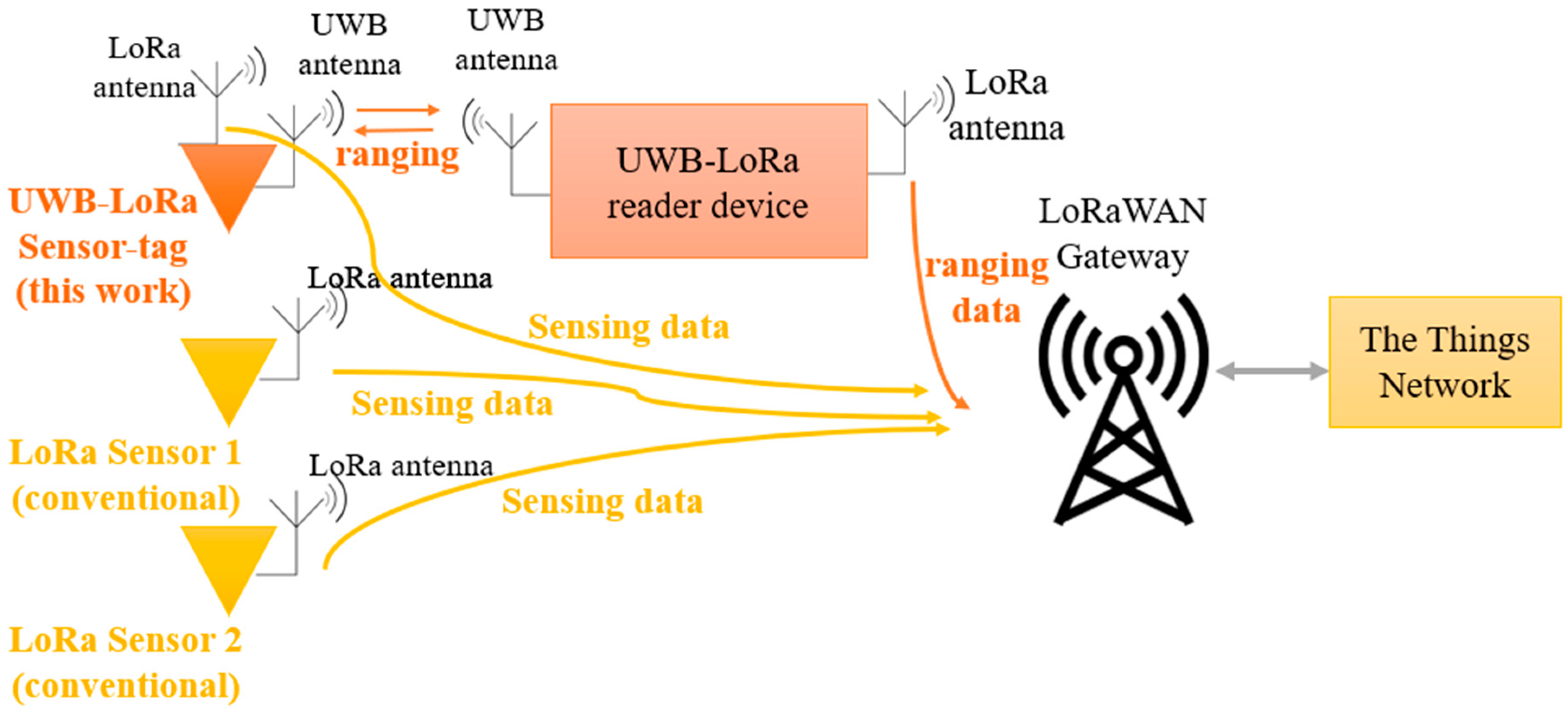
Figure 1 shows the working transmission chain related to the context in which the LoRa-UWB transceiver is set to operate. As an example, the chain consists of several LoRa sensors deployed in different locations that communicate with a LoRaWAN gateway, as conventionally performed. In addition to these tags, a UWB-equipped LoRa sensor-tag is placed and can directly communicate with either the gateway to transmit sensing data, or an UWB-LoRa reader device to perform two-way ranging, obtain the Time-of-Flight (ToF) at the reader node and compute the distance between the two measures. The reader then sends the ranging information to the gateway through LoRa signals. Since the gateway is knowledgeable a priori of the reader’s location, it can determine the location of the sensor-tag and monitor its movement in the environment.

Figure 1.
Communication chain structure from the sensor tags to the network and gateways.
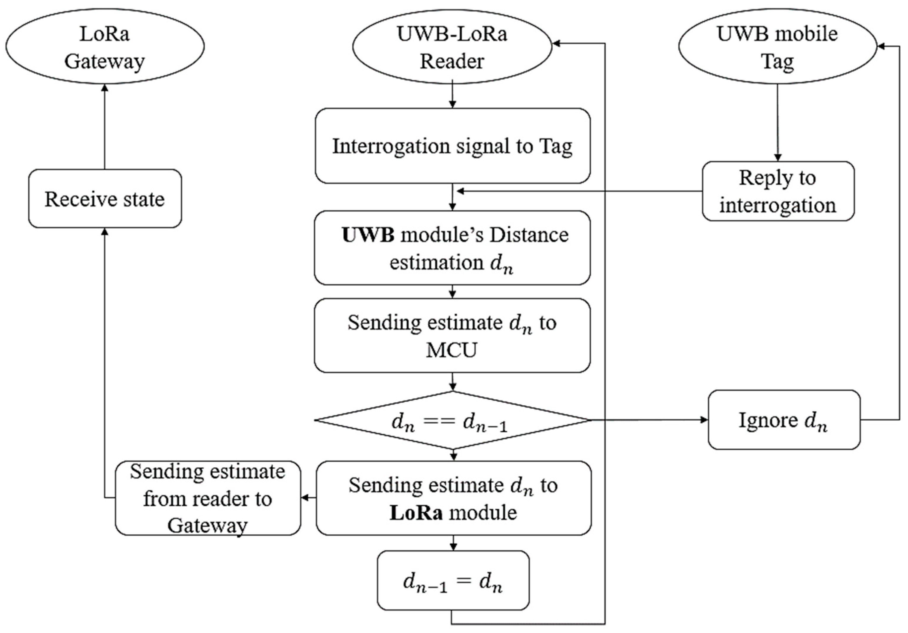
Figure 2 presents the working organigram of the system and the roles of each node in more detail. It consists of the LoRa gateway, a sensor-tag and a UWB-LoRa reader that acts as an intermediate node between the two features. In this setting, the gateway is required to determine the location of the sensor-tag, especially if this location is moving in its environment.

Figure 2.
Organigram of the working localization system highlighting the role of each node.
Following the ranging principle and using UWB technology, the reader sends an interrogation signal to the sensor-tag, to which the tag replies via an acknowledgment signal. Through the measure of ToF of these signals, the reader obtains the ranging estimate , which is the distance between the sensor-tag and itself. Although all these steps have been realized through the UWB protocol, the reader then enters a decision phase: whether or not to send the obtained location estimate to the LoRa gateway. The decision is taken after comparing the actual distance value to the previous one in an a priori stocked manner. The reader will only send the location of the sensor to the gateway if this sensor has moved and changed location since the last measure. A Microcontroller Unit (MCU) ensures the communication between the reader’s UWB and the LoRa modules. If the new distance estimate is not different from , it is ignored, and the interrogation is again sent to the sensor-tag. If it is different, it means that the tag has moved and its location has changed. In this case, the estimate is sent to the LoRa module and automatically sent from this module to the LoRa gateway through LoRa antennas, and is stocked by replacing for the next loop iterations.
The main advantages of the presented localization technique are as follows:
- The accuracy of the localization is of UWB-level accuracy, which is approximately 15 to 20 cm and in some cases even less. This accuracy cannot be achieved using standard LoRa localization schemes, as LoRa is a narrowband communication technology. At the receiving stage of the broadband time domain signal, it is difficult to precisely determine the arrival time compared to UWB narrow time pulses.
- The ability to achieve the real-time property of the localization thanks to UWB while still consuming as little power as possible. Real-time localization with LoRa-only systems is not possible, as, in this case, the LoRa module needs to send the received packet from the tag to the gateway. This packet contains the time of flight, which makes it necessary to estimate the location at the gateway side each time; without knowing if the tag has moved or not, this continuous packet transmission would consume more power, which is against the LoRa principle.
- UWB and LoRa based systems are mostly active (battery powered) in the proposed system, as the UWB battery powers both the UWB and LoRa modules. As LoRa’s power consumption is very low, another power unit is not necessary.
3.2. Design of the LoRa-UWB Transceiver
The designed UWB-LoRa transceiver is a multi-standard device capable of achieving the high-accuracy and long-range UWB localization of objects and sending the location information to LoRa gateways. Its main purpose is to act either as a sensor-tag or a reader intermediate node between the sensor-tag and the gateway. It performs the localization of the tag and informs the gateway in case this latter has moved in space.
The reader is composed of an UWB module (from STMicroelectronics [24]) and a LoRa module, which communicate through an MCU unit. Hence, the reader has an UWB antenna for RF communication with any UWB module and a LoRa antenna for the RF communication with the LoRa gateways. The UWB module and the antennas of the reader and tag’s working frequency channel is the UWB channel 2, which starts at 3.75 GHz and ends at 4.25 GHz. The LoRa module and antennas work in the 863 to 868 MHz band, which represents the Europe frequency channel for LoRa communications, and it is part of the unlicensed Industrial, Scientific and Medical (ISM) bands.
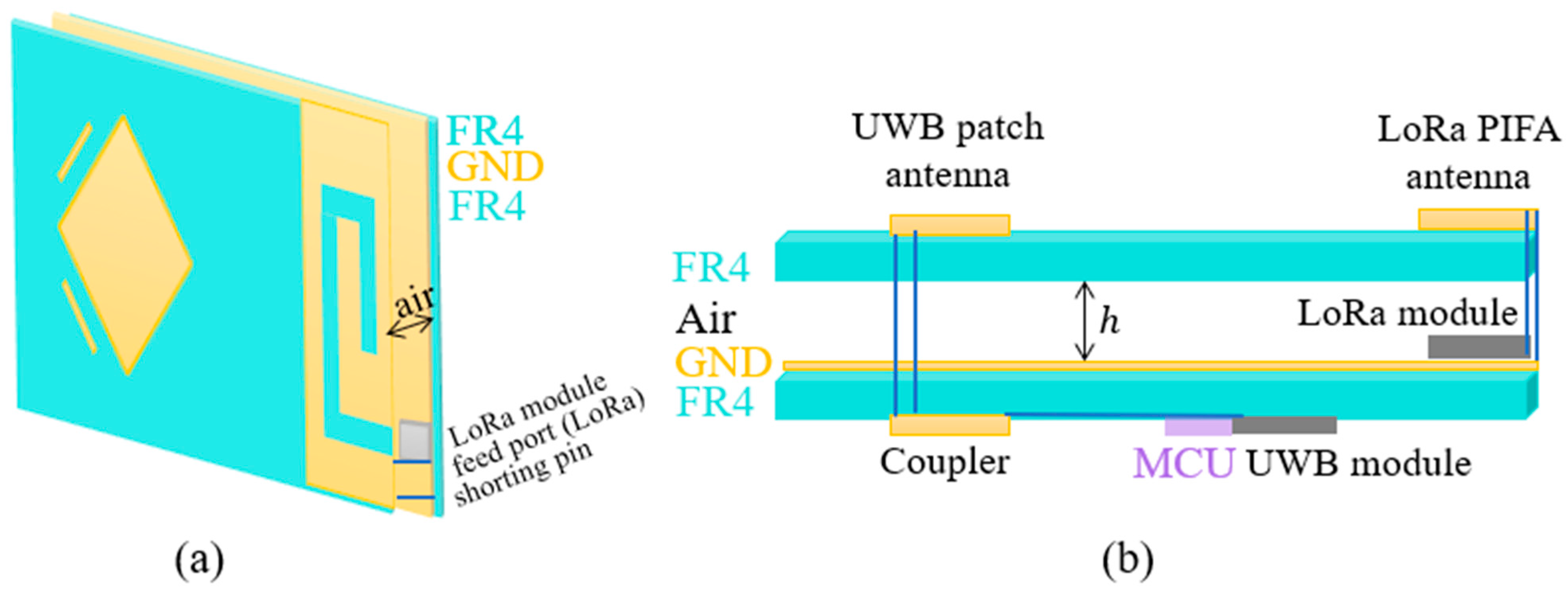
As illustrated in Figure 3, the reader board consists of a upper layer and a bottom layer separated by an air gap. The upper layer consists of the radiating elements of the UWB and LoRa antennas placed on the same FR4 substrate. In contrast, the bottom layer consists of the ground plane and the LoRa module on one side, while on the other side, an FR4 substrate with a branch-line coupler enabling the UWB circular polarization of the UWB antenna is placed, and at a distance from it, the MCU and UWB module are integrated.

Figure 3.
Structure of the UWB-LoRa transceiver: (a) perspective view; (b) side view. Structure composed of two layers: an electronics bottom layer and an antenna upper layer, connected through signal vias.
Circular polarization was privileged for the UWB antenna, as it is more advantageous due to it yielding better localization information and ranges compared to linear polarization; its advantages are described in detail in our previous works [14,25]. The common air gap between the two antennas serves as the air gap for standard PIFA (Planar Inverted F-Antenna) design and simultaneously represents the necessary gap between the substrate and ground, which guarantees a 500 MHz bandwidth for the UWB probe-fed patch antenna.
Concerning the electronic part of the transceiver, the system complexity has been kept at a low level during the design process. The main components are the power supply unit, the MCU, the LoRa module and the UWB module. The first three are mandatory and equivalent to any LoRa/LoRaWAN end-devices available on the market, and the circuit connections between them are accordingly made to the conventional systems. In addition, the required connections for the UWB module were realized following the same model and firmware derived from the STMicroelectronics UWB MEK1 localization board [20]. Finally, the UWB module is connected to the MCU, which is also connected to the LoRa module.
Furthermore, the commercial cost of the LoRa module and MCU prevalent is low (within 10 USD), and with the recent announcement of the STM32WL microcontroller from STMicroelectronics, the foreseeable cost will be even lower thanks to the integration of the LoRa Module into the same die of the microcontroller. In contrast, the costs of the UWB modules currently vary depending on their integration boards. In this work, the module was provided as samples and are only commercialized with the MEK1 board; however, other UWB modules are available at a relatively low price (within 25 USD), such as modules from Decawave. To conclude, the proposed concept of UWB-LoRa localization can be applied and remains feasible, regardless of the types of the LoRa or UWB modules chosen.
3.3. Antenna Structure Design
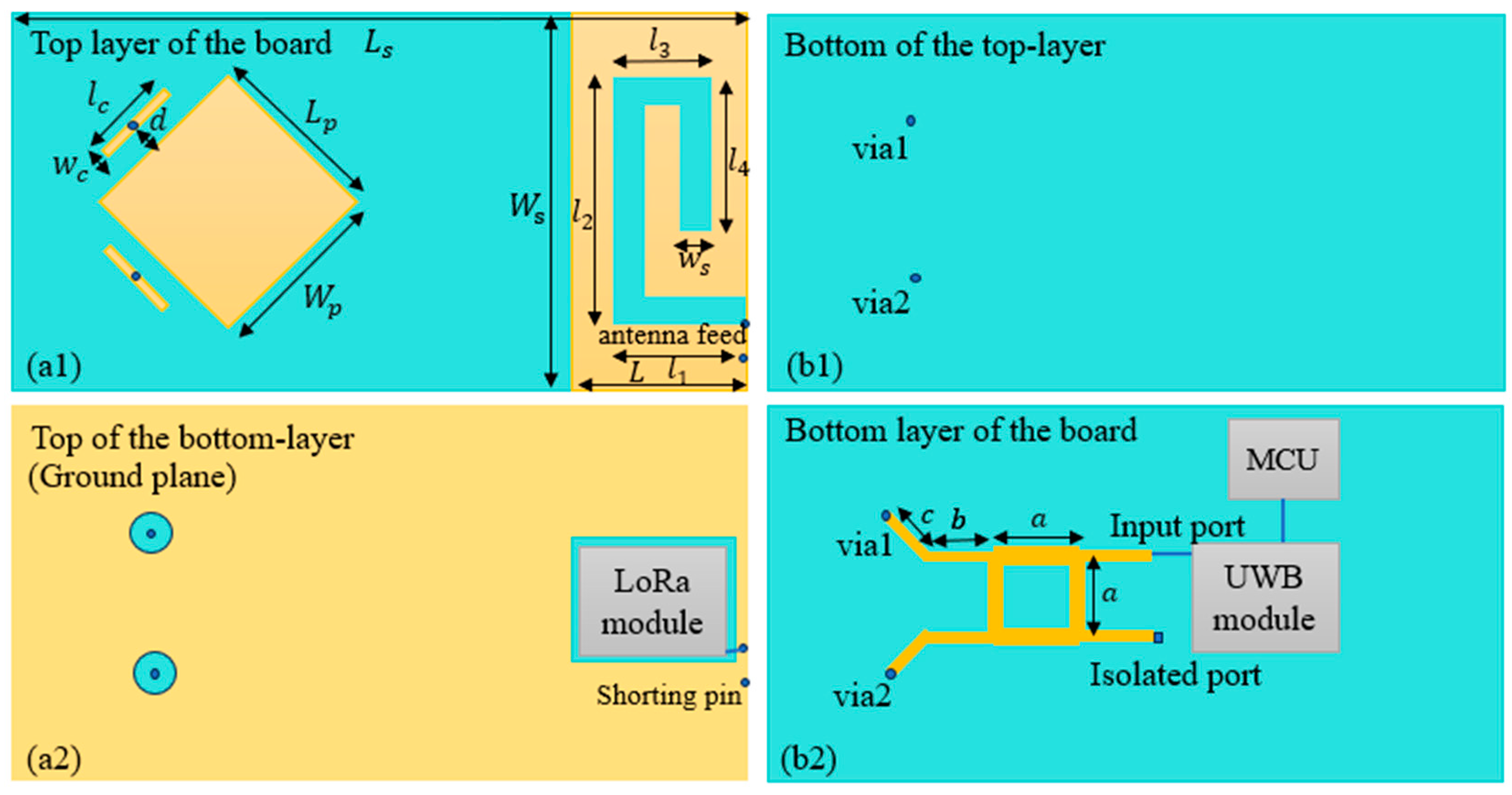
The structure is composed of two antennas (Figure 4): a wideband patch antenna operating at the UWB channel from 3.75 to 4.25 GHz and a PIFA antenna operating at the LoRa channel from 863 to 870 MHz. The design and simulation were realized using CST Microwave software (https://www.3ds.com/products-services/simulia/products/cst-studio-suite/), where only the antenna parts of the board were simulated, and the electronics modules positions were considered by leaving the necessary space for their integration, which occurs later in the fabrication process.

Figure 4.
Antenna structure design consisting of a UWB patch antenna and a LoRa PIFA antenna: (a1) top of the upper layer of the board; (b1) bottom of the upper layer of the board; (a2) top of the bottom layer of the board; (b2) bottom of the bottom layer of the board.
As the transceiver has two substrates, the radiating elements of both the UWB and LoRa antennas are placed on the upper layer substrate. The bottom layer contains other antenna elements: the ground plane shared by both antennas; the shorting pin of the LoRa antenna, which extends until the ground plane; the feed vias; and the branch-line coupler of the UWB antenna placed on the back surface of the bottom substrate. Both substrates used are of the FR4 type and have a 0.8 mm thickness.
The UWB antenna design and optimization procedure is detailed in [26], and it is a probe-fed wideband patch using capacitive feeding from a small conductor printed next to the radiating element. Since it is also designed to have circular polarization, two orthogonal capacitive elements are designed. These two small rectangular elements are fed with vias originating from the coupler outputs placed at the bottom layer. The dimensions of the UWB antenna (Figure 4) are as follows: the substrate length and width are, respectively, and . The patch dimensions are , designed via a standard method to work at a center frequency of 4 GHz. Each capacitive element’s length and width are and , respectively, and the distance separating it from the radiating element is . Finally, the classical branch-line coupler is designed to operate at the same center frequency of 4 GHz, from which its dimensions are derived.
The LoRa antenna is a slotted PIFA antenna. The slot starts from the feed point and extends to help decrease the resonating frequency to the desired LoRa channel frequencies. The external dimension of the antenna (Figure 4) is , and its width is the same as the substrate width (. The slot width is 2.5 mm, and its length dimensions are , , and . The feed and short points are separated by a distance of 2.5 mm. All antenna dimensions are summarized in Table 1.

Table 1.
Summary of the physical dimensions of the antennas.
As both antennas share the same ground plane, the air gap between this factor and the upper layer substrate is an optimized distance of 7 mm. The optimization of this distance to accommodate both antennas is highly important, as it significantly affects the patch bandwidth and the PIFA antenna’s resonance performance.
4. Results
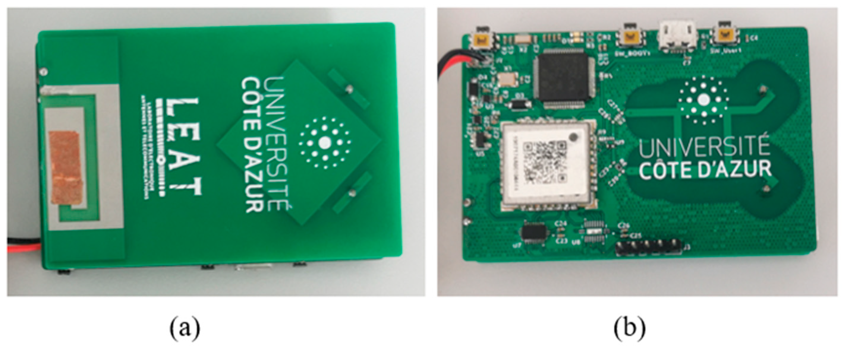
A prototype of the UWB-LoRa transceiver was realized and is presented in Figure 5. The upper and bottom layers were realized separately and then assembled via the soldering of the feed connections from the coupler outputs to the capacitive small patches next to the radiating element for the UWB antenna, as well as the feed and shorting connections from the ground plane to the upper layer PIFA element. The transceiver board was powered by a small external battery, and both antennas’ inputs (LoRa and UWB) were powered by a signal coming from their respective modules, as shown in Figure 3.
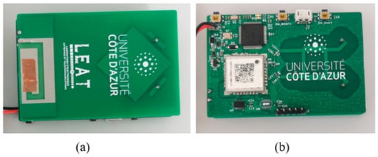
Figure 5.
Prototype of the UWB-LoRa transceiver board: (a) the upper layer of the board containing the radiating elements; (b) bottom layer of the board containing the MCU, the modules and the branch-line coupler.
4.1. Antenna Measurements
4.1.1. Impedance Matching
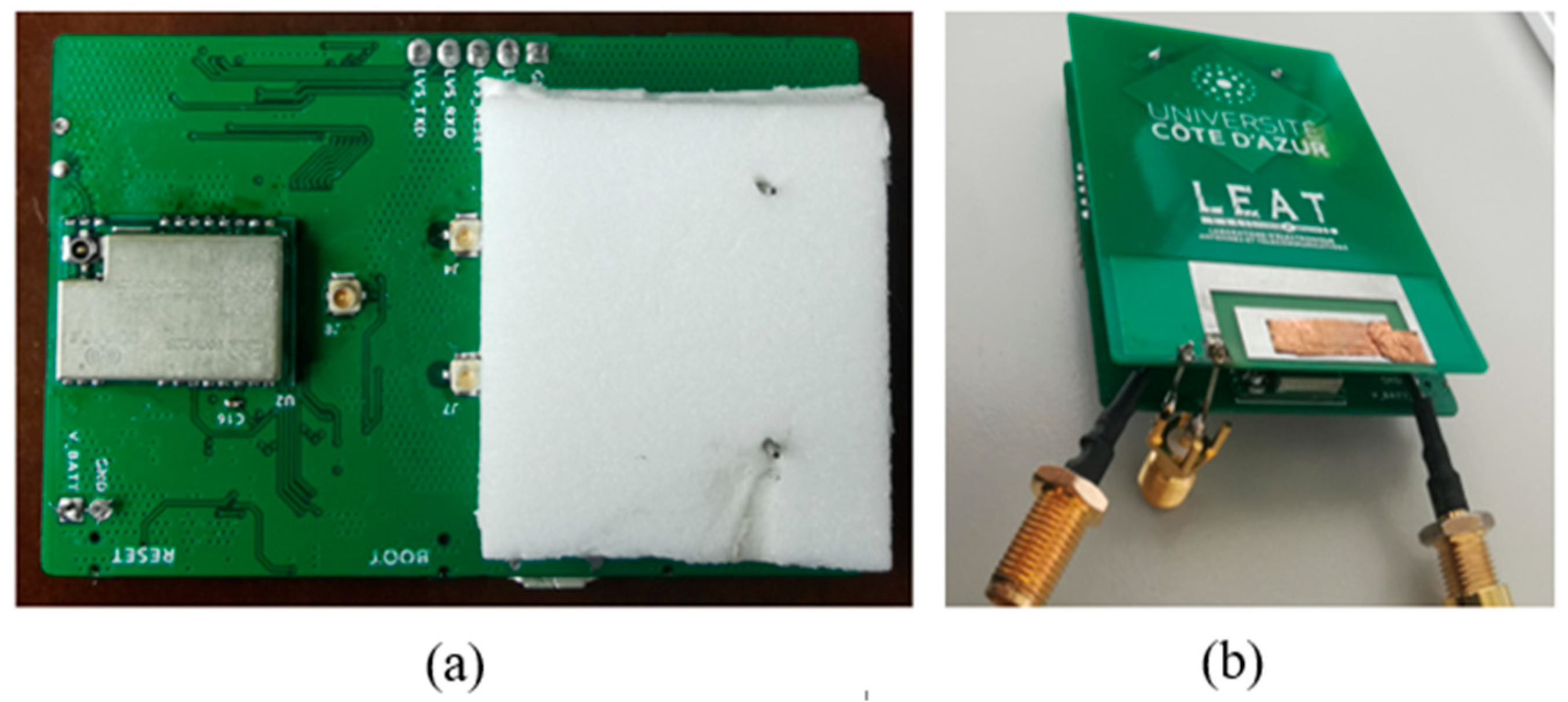
To measure the impedance matching of the antennas before testing the board, UFL-type connections were designed a priori at both inputs of the branch-line coupler (which represent the two input ports of the UWB antenna), and UFL-to-SMA cables were used for measurements using a Vector Network Analyzer (VNA), as illustrated in Figure 5 and Figure 6.
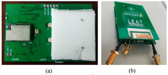
Figure 6.
Board assembly and measurements: (a) prototyping using foam to separate the layers and UFL connectors at the coupler inputs; (b) stand-alone antenna matching measurement set up, using a SMA connector for the LoRa antenna and UFL-to-SMA cables from the coupler inputs for UWB antenna characterization.
The SMA side of the cable connected to one of the coupler’s inputs (the isolated input port) is then loaded via a 50 Ω match. In the case of the LoRa antenna, it can be seen that its feed was directly connected to an SMA connector for the measurements (Figure 5). Foam with the same dielectric constant as air was also used between the two layers of the board to facilitate the assembly of the board.
Figure 7 presents the simulated and measured reflection coefficient of the PIFA antenna. Our results show a shift in frequency between the simulation and measurement. This shift is due to the slot of length , which was removed by covering it with copper tape in the fabricated prototype, as shown in Figure 5a and Figure 6b. In fact, the simulated result with the slot shows that the antenna resonated at the desired frequencies; however, after the prototyping, it was observed that lowered the resonance frequency below 850 MHz, which is why it was covered. A slight difference in bandwidth is also observed, which is due to the reflection coefficient being higher after adjusting the frequency, which led to the dampening of the bandwidth. Finally, the measured result shows that the antenna’s impedance is matched at −10 dB from around 845 to 875 MHz, which includes the desired LoRa channel (863 to 868 MHz) for LoRaWAN communication with the sensors and gateways.
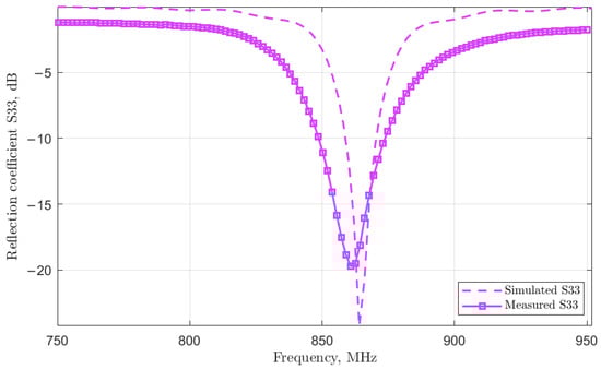
Figure 7.
Reflection coefficient of the LoRa PIFA antenna.
The simulated and measured reflection coefficient of the UWB antenna is illustrated in Figure 8. This coefficient was measured separately, via two measurements, for both ports corresponding to the two inputs of the branch-line coupler by alternating the isolation load between the two inputs. In both cases, one of the ports must be isolated with a 50 Ω load. The advantage of choosing which port is the input to the antenna is that the sense of the circular polarization can be chosen, that is, left or right circular polarization can be obtained. The ability to choose the polarization sense implies that the antenna can be integrated into different systems regardless of polarization specifications, such as in cases where, for example, the reader and tag antennas are required to have a specific polarization sense or the polarization of a reader (or tag) antenna is required to match the polarization of a tag (or reader) antenna.
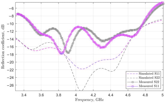
Figure 8.
Reflection coefficients of the UWB patch antennas for both ports of the coupler (S11 and S22).
A comparison between the simulation and measurement shows that the impedance matching of the antenna via simulation presents better results, as it ranges between −20 and −28 dB, compared to −12 and −18 dB in the measurement. This difference is due to factors such as the possible difference in air gap during the assembly process, which can have a significant effect on the bandwidth and impedance matching; another factor is the electronics modules and circuits, which were not simulated with the antenna design. Finally, regardless of the port chosen, our results show that the antenna’s measured reflection coefficient is matched at −10 dB (from ~3.55 GHz to ~4.74 GHz), which includes the desired UWB channel (3.75 GHz to 4.25 GHz) in both cases. A slight difference between the two curves is observed, which is due to the presence of the PIFA antenna, which is not completely symmetrical with respect to the antenna axis.
4.1.2. Efficiency and Gain
Further antenna measurements were realized in an anechoic chamber to assess the gain and radiation efficiencies of the antennas. Figure 9 and Figure 10 show the simulated and measured characteristics, respectively, for the LoRa and UWB antennas.
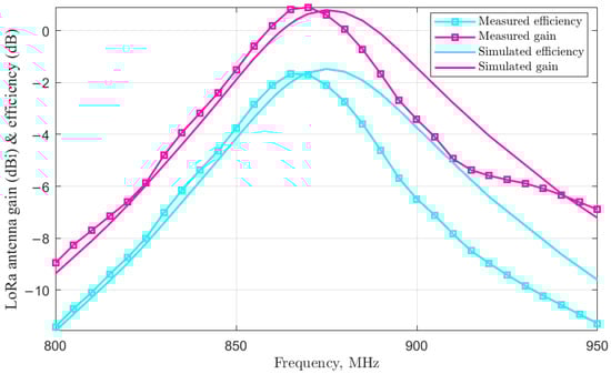
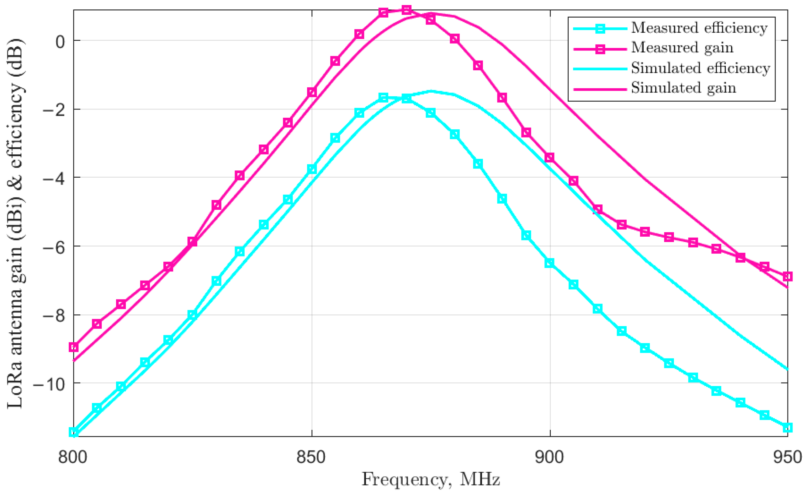
Figure 9.
Measured LoRa antenna’s gain and efficiency characteristics.
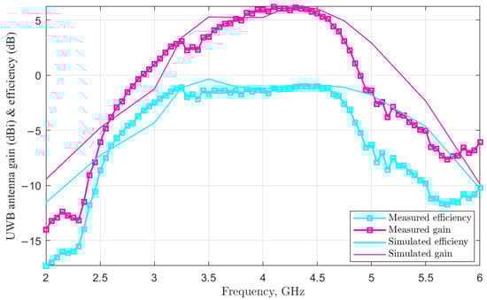
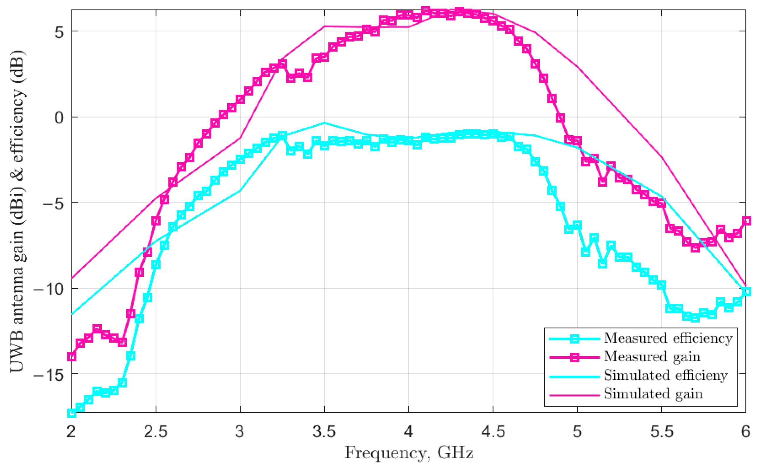
Figure 10.
Measured UWB antenna’s gain and efficiency characteristics.
The result of the measurement of the LoRa antenna shows a maximum efficiency and gain at the operation frequency channel (863–870 MHz). The gain ranges between 0.82 and 0.91 dBi, while the efficiency is between −1.65 and −1.69 dB (corresponding to 68% of the radiation). A shift in frequency is observed between the measured and simulated curves for both the efficiency and gain, which is due to the simulated design including the slot , in contrast to the prototype, in which it was removed to adjust the resonant frequency.
Furthermore, the UWB antenna’s simulated and measured efficiency and gain are illustrated in Figure 10. The results show stable gain and efficiency along the desired frequency channel (3.75–4.25 GHz) in terms of both simulation and measurement. Furthermore, the measured gain ranges between 5.1 dBi and 6 dBi on these frequencies, where this variation of less than 1 dB is small enough to ensure that the antenna behavior is considered identical at all the frequencies of the channel. Similarly, the radiation efficiency varies between −1.26 and −1.4 dB, which corresponds to radiation of between 72 and 75%.
4.1.3. Radiation Pattern
Figure 11 illustrates the measured radiation pattern of the UWB antenna through the realized gain of the co-polarization and cross-polarizations (here, the measurements correspond to one arbitrary chosen port). The pattern is measured in terms of the UWB channel’s center and edge frequencies (3.75 GHz, 4 GHz and 4.25 GHz) to ensure the stability of its wideband operation.
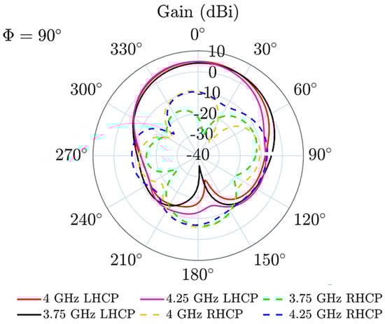
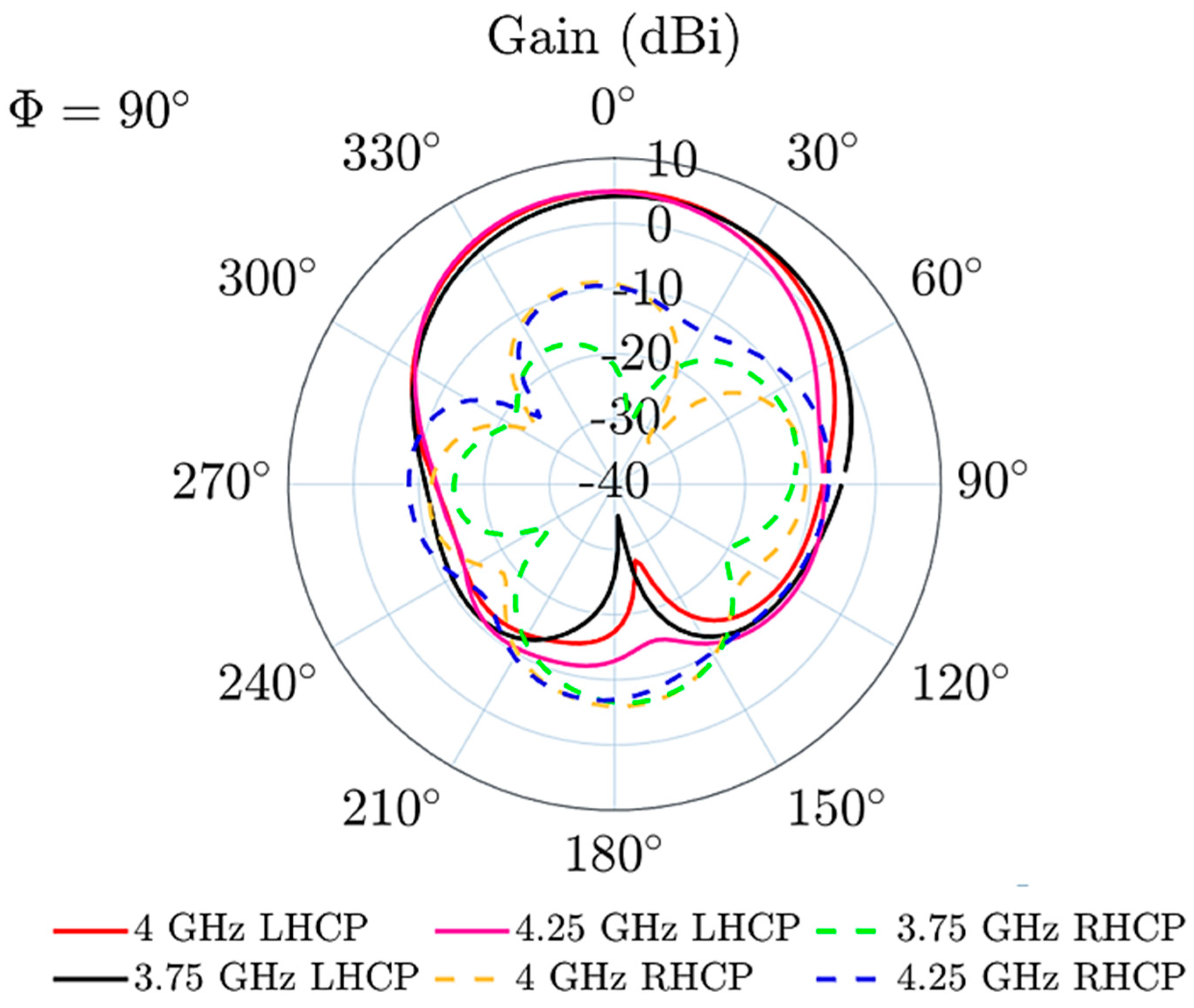
Figure 11.
Radiation pattern (azimuth) of the UWB antenna at the channel’s center and edge frequencies through polarization-realized gain.
As shown in the results, the antenna exhibits a 180° directional azimuth pattern at all frequencies, and the circular polarization sense achieved is left hand (for the measured port), with stable peak gains of ~6 dBi.
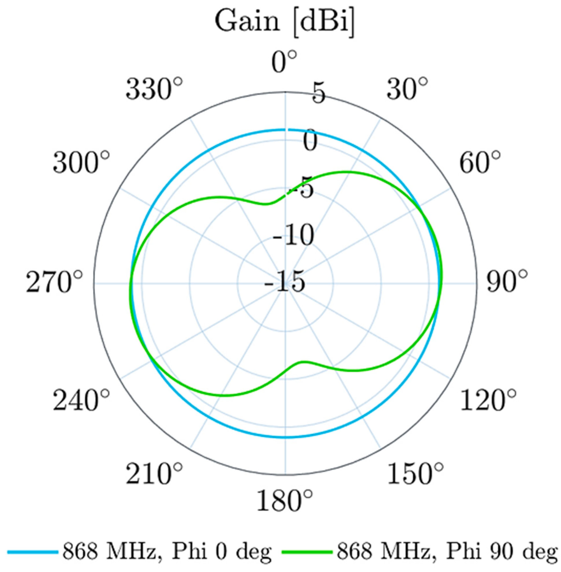
Figure 12 illustrates the simulated radiation pattern (realized gain) of the LoRa PIFA antenna around the transceiver board at a frequency of 868 MHz. As shown in these results, the antenna exhibits an omnidirectional radiation pattern and showcases two radiation dips along the PCB axis. The antenna achieves measured peak gains between 0 and 1 dBi.
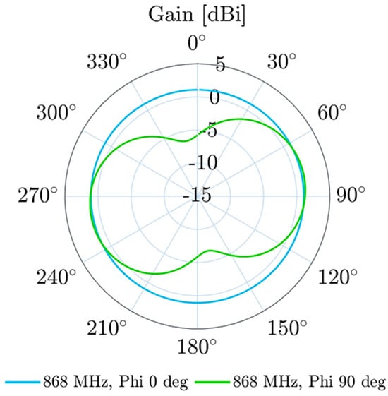
Figure 12.
Radiation pattern of the LoRa antenna at a frequency of 868 MHz.
5. Discussion
To assess the localization performance, two steps are investigated. The first one is the UWB two-way ranging realized between the sensor-tag and the reader, and the second one is the transmission of the location information to the LoRa gateway and network. These steps are detailed in the following section.
5.1. From the Sensor-Tag to the Reader
Ranging measurements were performed using two prototypes of the UWB-LoRa transceiver, with one used as a sensor-tag and another one used as a reader. It is important to note that experimental tests with UWB signals are not prone to interference with other devices operating in the same environment [27,28] because they are spread over a wide band and transmitted at power spectral density levels close to the noise floor of conventional radio receivers, such as WiFi, Bluetooth, etc.
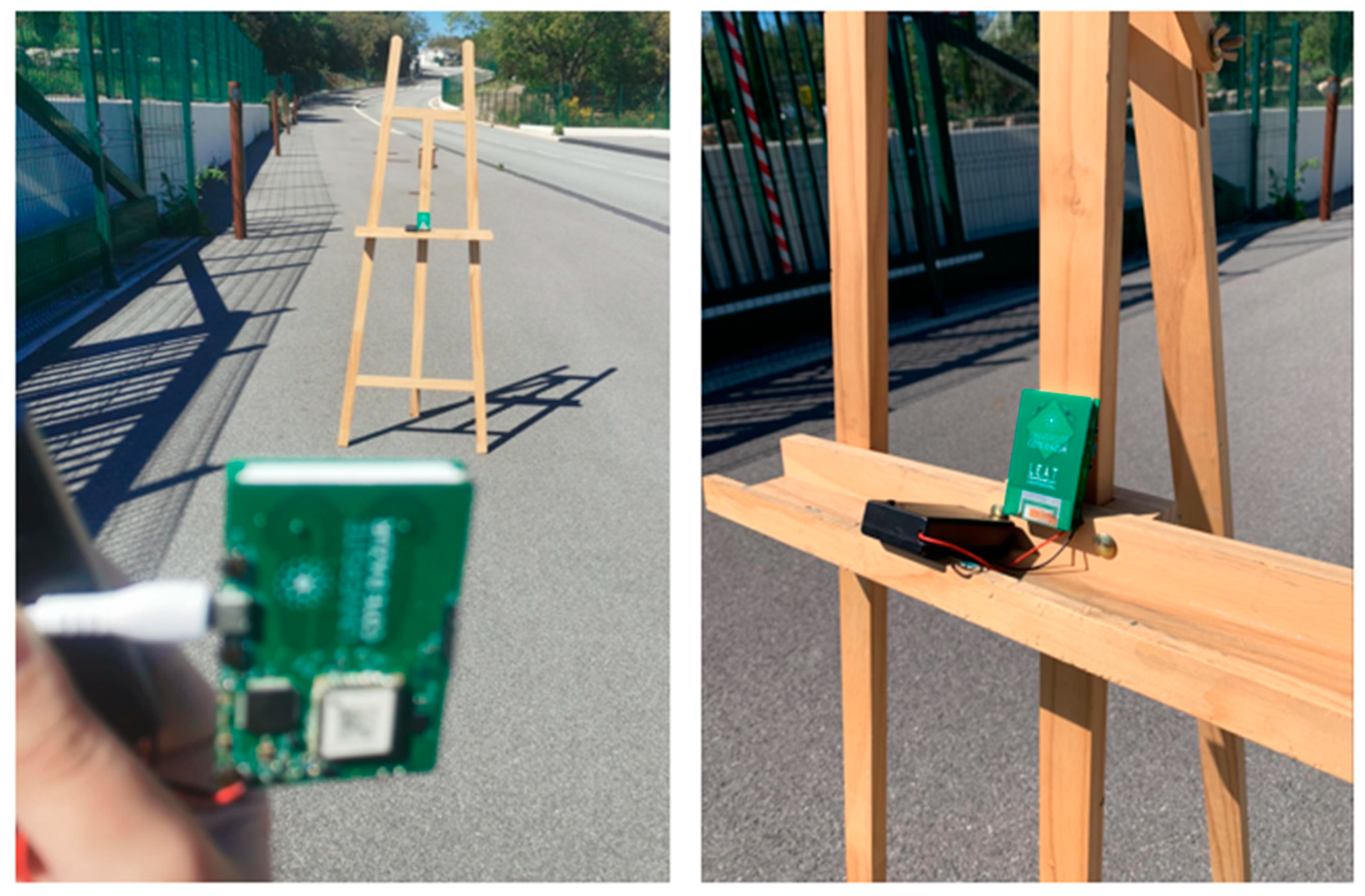
Figure 13 shows the measurement setup and environment. An outdoor scenario was privileged, as it enables more available space compared to buildings, allowing us to measure the performance at LOS and analyze the maximum range of detection that is achieved through UWB localization. This range does not describe the whole system’s UWB-LoRa range but only that of the UWB part of the system. This maximum distance gives an idea of where the intermediate reader node needs to be placed in such system, that is, how far from the sensor-tag it can be placed and still be able to detect it.

Figure 13.
Ranging performed via two LoRa-UWB transceivers, with the first being a sensor-tag and the second being a reader.
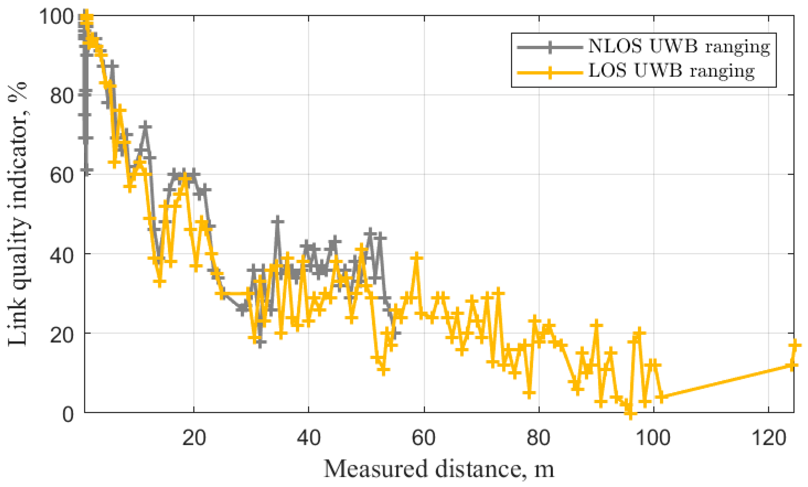
Figure 14 illustrates the result of the ranging through the Link Quality Indicator (LQI) with respect to the distance measured via the reader (using its UWB feature). The LQI is the ratio of the measured received signal strength to the already-known saturation signal strength of the transceiver. It is a metric used by STMicroelectronics for localization using their UWB module, which was integrated into the designed transceiver.

Figure 14.
Ranging measurements of the UWB localization between the sensor-tag and the reader in LOS and NLOS scenarios (outdoor).
Firstly, the results show that the LQI and, thus, the received power decreases with respect to the distance, which is due to signal path loss. Indeed, having higher levels of power is beneficial for obtaining longer ranges of detectability. For this reason, solutions to overcome path loss exist in the literature and include the modeling of the UWB propagation channel [29,30], the estimation of the channel path loss [31] and the compensation for it at the signal processing level; however, the objective in this work leans more toward demonstrating the feasibility of the UWB-LoRa localization concept by comparing it to conventional UWB and LoRa localization systems, the performances of which are known in terms typical range and accuracy.
Thus, the second observation from these results is that the reader can detect the mobile sensor-tag up to distances of ~120 m and ~55 m in the LOS and NLOS scenarios. The LQI naturally decreases with the increase in distance and presents small fluctuations between close-distance measurements, as it depends on the environment around the mobile tag at that time instant. The observed LQI dip at the start of the LOS measurement is simply due to the initialization phase trial measurement and can be ignored. The ranges achieved conform with typical maximum UWB ranges present in systems used in industry and the literature (approximately 100–200 m for LOS).
It is necessary to mention that the LoRa feature of the sensor-tag in this work does not have a role in the UWB localization process, which involves ToF measurements. Indeed, its role is like that of any LoRa sensor, i.e., to allow the direct transmission of sensing information to the gateway, which does not require sending it to the intermediate reader. Indeed, the intermediate reader and UWB communication part of the sensor-tag only intervene if the sensor-tag has to be located via the gateway.
5.2. From the Reader to the Gateway and Network
After the ranging is performed, the reader node sends the location information of the sensor-tag to the LoRa gateways, albeit only in case the latter has moved since the last measurement. The reader transceiver compares the current obtained distance separating it from the sensor-tag and the previously computed distance. If it is different, the reader sends the information through LoRa to the gateway. Figure 15 shows the information packet received by the network, and it displays the reader and the sensor-tag’s Identification Numbers (ID), the distance measured and the Link Quality Factor (LQI).
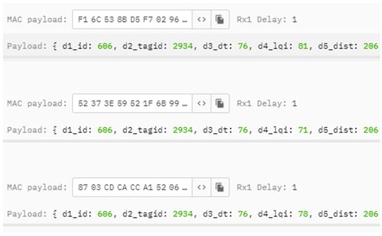
Figure 15.
Ranging information of the sensor, as displayed after its reception via the LoRa network.
These results demonstrate that as long as the UWB-LoRa reader node is placed at an appropriate distance from a LoRa-UWB (or UWB-only) sensor-tag, it is able to localize through UWB high-accuracy ranging. The LoRa gateways placed at distances of kilometers from a sensor will be able to monitor this latter feature and stay informed of its precise location whenever it changes in real time.
5.3. Localization Accuracy
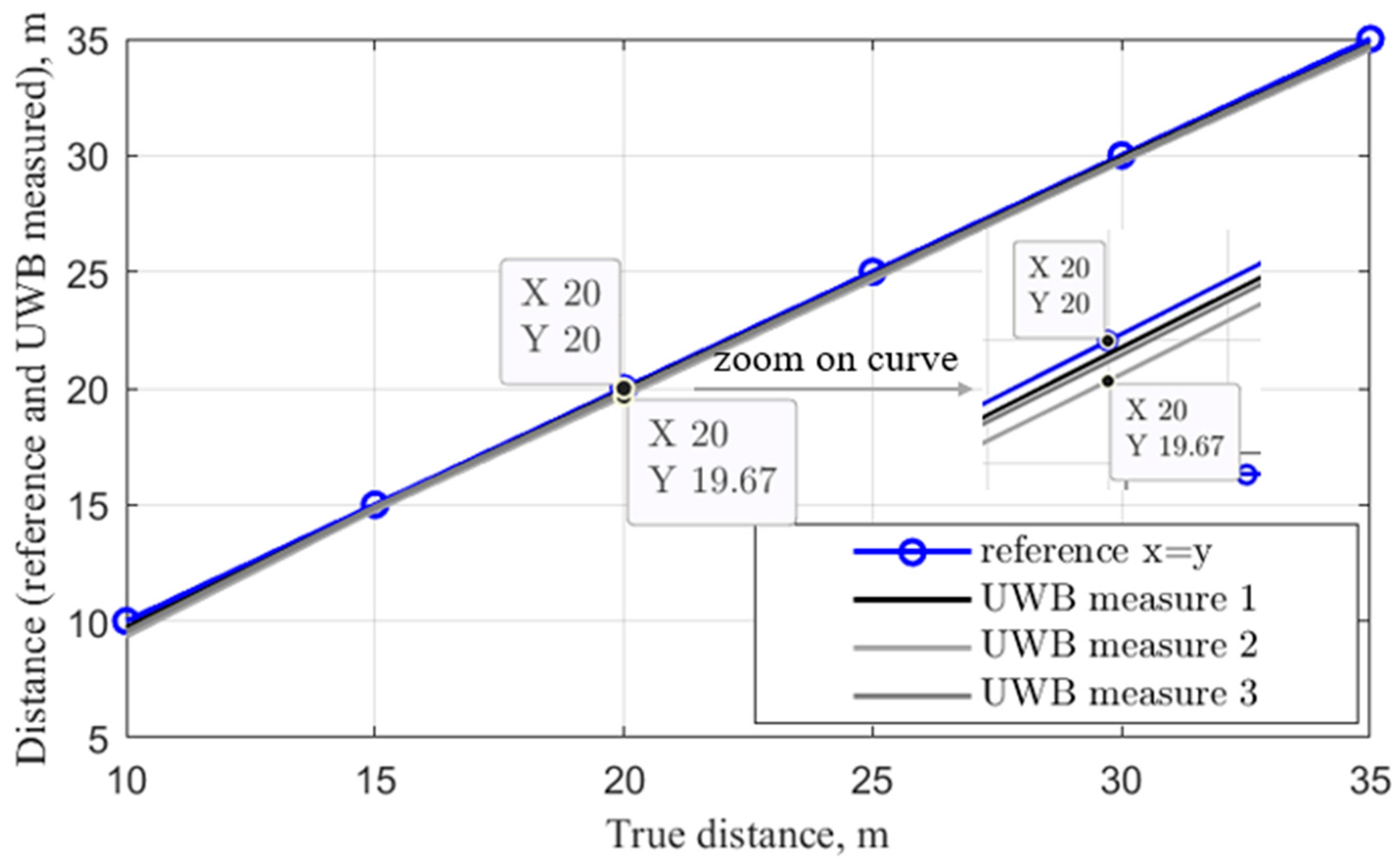
Localization using UWB is known to ensure the accuracy of the location information that is of a sub-meter level. To observe this process, ranging measurements were realized with the designed transceivers in an indoor scenario, where multipath effects were often present, along a limited corridor of 35 m inside the LEAT laboratory. The reader transceiver was placed at a fixed position, and the tag was moved, starting from 10 to 35 m away from the reader. The measurements of the distance between the reader and tag were performed for each step of 5 m. This operation was repeated three times, and the measured distances were compared to the true distance between the reader and tag. Figure 16 illustrates this comparison for all three measures.
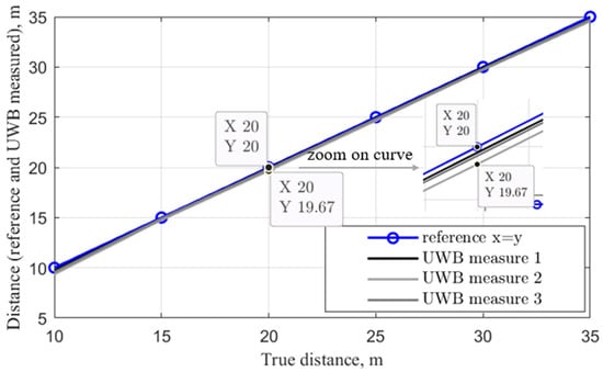
Figure 16.
Comparison of UWB-measured distances with the true distance between a reader and a tag in an indoor environment.
The results show that for all three measures, the distance measured via the UWB reader follows the reference curve (true distance) very closely. Measure 2 seems to show the furthest measure from the reference curve; however, its accuracy remains at the sub-meter level. Indeed, an example is shown at the 20 m distance, where the UWB reader’s distance estimation is 19.67 m, which corresponds to an estimate error of only 33 cm. All the other estimates (measure 1 and 3) achieve lower estimate errors of between 10 and 30 cm. This result allows us to confirm the achieved sub-meter accuracy due to UWB signals’ fine temporal characteristics (pulse width of ~2 ns). The achieved centimeter-level accuracy with UWB greatly benefits the LoRa infrastructure; indeed, the conventional localization attempts using only the LoRa technique to allow a gateway to locate a sensor, as shown in the literature, are typically characterized by accuracy levels that exceed ~10 m using Time-of-Flight measurements, which may be low enough for outdoor approximate localization; however, this accuracy level cannot accommodate indoor environments.
6. Conclusions
This paper investigated the possibility of achieving high-accuracy, long-range localization through UWB and LoRa technologies. A multi-standard transceiver board was proposed as a solution. It consists of a UWB module, a LoRa module and an MCU, ensuring the communication between them. The transceiver can either be a sensor-tag deployed in the LoRa infrastructure, a reader device, or both. It allows the localization of a sensor-tag with UWB-level accuracy (a few centimeters) and the transmission of the location information to LoRa gateways kilometers away from the sensor-tag to the network. The UWB-LoRa transceiver was fabricated, and two prototypes were used for ranging measurements in both outdoor and indoor scenarios. The results demonstrated conformal UWB localization ranges and accuracy, as well as their successful transmission to the LoRa gateway for the real-time monitoring of the sensor, all while maintaining the low power requirements of the LoRa communications. In future work, the improvement in the proposed localization transceiver could focus on the miniaturization aspect of the antennas, especially for the sensor-tag, to help its integration into different objects that need to be tracked. The miniaturization can be achieved by choosing a higher frequency channel and optimizing the antennas accordingly. Another improvement aspect would be the integration of direction detectability in addition to ranging, and this can be achieved via the design of an antenna array for the reader side, which can intercept the ranging signals using the array elements and determine the angles of arrival related to the direction component.
Author Contributions
The individual contributions of the authors to the realization of this work is as follows: Conceptualization, F.F.; methodology, F.F., A.B. and T.M.N.; software, T.M.N. and A.B.; validation, F.F., R.S. and L.L.; formal analysis, F.F.; investigation, A.B. and T.M.N.; resources, F.F.; data curation, A.B. and T.M.N.; writing—original draft preparation, A.B.; writing—review and editing, F.F., R.S. and L.L.; supervision, F.F., R.S. and L.L.; project administration, R.S.; funding acquisition, R.S. All authors have read and agreed to the published version of the manuscript.
Funding
This research was realized within the framework of the LEANPOD project and funded by the Nano 2022 project, grant number 198938.
Data Availability Statement
Software and firmware data for the operation of the designed UWB-LoRa transceiver are available online via this link: https://github.com/nguyenmanhthao996tn/LoRaUWB_demo_single_master_slave (accessed on 10 July 2023).
Acknowledgments
The authors would like to thank the company BeSpoon (which recently joined the STMicroelectronics company) for their support by providing their UWB module samples that were integrated into the designed transceiver prototypes.
Conflicts of Interest
The authors declare no conflict of interest.
References
- Khutsoane, O.; Isong, B.; Abu-Mahfouz, A.M. IoT devices and applications based on LoRa/LoRaWAN. In Proceedings of the IECON 2017—43rd Annual Conference of the IEEE Industrial Electronics Society, Beijing, China, 29 October–1 November 2017; pp. 6107–6112. [Google Scholar] [CrossRef]
- Merhej, D.; Ahriz, I.; Garcia, S.; Terré, M. LoRa Based Indoor Localization. In Proceedings of the 2022 IEEE 95th Vehicular Technology Conference: (VTC2022-Spring), Helsinki, Finland, 19–22 June 2022; pp. 1–5. [Google Scholar] [CrossRef]
- Marquez, L.E.; Calle, M. Understanding LoRa-Based Localization: Foundations and Challenges. IEEE Internet Things J. 2023, 10, 11185–11198. [Google Scholar] [CrossRef]
- Mekki, K.; Bajic, E.; Chaxel, F.; Meyer, F. A comparative study of LPWAN technologies for large-scale IoT deployment. ICT Express 2019, 5, 1–7. [Google Scholar] [CrossRef]
- Augustin, A.; Yi, J.; Clausen, T.; Townsley, W.M. A Study of LoRa: Long Range & Low Power Networks for the Internet of Things. Sensors 2016, 16, 1466. [Google Scholar] [CrossRef] [PubMed]
- Devalal, S.; Karthikeyan, A. LoRa Technology—An Overview. In Proceedings of the 2018 Second International Conference on Electronics, Communication and Aerospace Technology (ICECA), Coimbatore, India, 29–31 March 2018; pp. 284–290. [Google Scholar] [CrossRef]
- Muppala, R.; Navnit, A.; Devendra, D.; Matera, E.R.; Accettura, N.; Hussain, A.M. Feasibility of Standalone TDoA-based Localization Using LoRaWAN. In Proceedings of the 2021 International Conference on Localization and GNSS (ICL-GNSS), Tampere, Finland, 1–3 June 2021; pp. 1–7. [Google Scholar] [CrossRef]
- Kombo, O.H.; Kumaran, S.; Bovim, A. Design and Application of a Low-Cost, Low- Power, LoRa-GSM, IoT Enabled System for Monitoring of Groundwater Resources With Energy Harvesting Integration. IEEE Access 2021, 9, 128417–128433. [Google Scholar] [CrossRef]
- Ferrero, F.; Truong, H.-N.-S.; Le-Quoc, H. Multi-harvesting solution for autonomous sensing node based on LoRa technology. In Proceedings of the 2017 International Conference on Advanced Technologies for Communications (ATC), Quy Nhon, Vietnam, 18–20 October 2017; pp. 250–253. [Google Scholar] [CrossRef]
- Dardari, D.; Closas, P.; Djuric, P.M. Indoor Tracking: Theory, Methods, and Technologies. IEEE Trans. Veh. Technol. 2015, 64, 1263–1278. [Google Scholar] [CrossRef]
- Dardari, D.; Conti, A.; Ferner, U.; Giorgetti, A.; Win, M.Z. Ranging with Ultrawide Bandwidth Signals in Multipath Environments. Proc. IEEE 2009, 97, 404–426. [Google Scholar] [CrossRef]
- IEEE Std 802.15.4z-2020; IEEE Standard for Low-Rate Wireless Networks–Amendment 1: En-Hanced Ultra Wideband (UWB) Physical Layers (PHYs) and Associated Ranging Techniques. IEEE: New York City, NY, USA, 2020; pp. 1–174.
- Coppens, D.; Shahid, A.; Lemey, S.; Marshall, B.V.H.C.; De Poorter, E. An Overview of Ultra-WideBand (UWB) Standards and Organizations (IEEE 802.15.4, FiRa, Apple): Interoperability Aspects and Future Research Directions. IEEE Access 2022, 10, 70219–70241. [Google Scholar] [CrossRef]
- Benouakta, A.; Ferrero, F.; Lizzi, L.; Staraj, R. Antenna Characteristics Contributions to the Improvement of UWB Real-Time Locating Systems’ Reading Range and Multipath Mitigation. IEEE Access 2023, 11, 71449–71458. [Google Scholar] [CrossRef]
- Pospisil, J.; Fujdiak, R.; Mikhaylov, K. Investigation of the Performance of TDoA-Based Localization Over LoRaWAN in Theory and Practice. Sensors 2020, 20, 5464. [Google Scholar] [CrossRef] [PubMed]
- Daramouskas, I.; Mitroulias, D.; Perikos, I.; Paraskevas, D.; Kapoulas, V. Localization in LoRa Networks Based on Time Difference of Arrival; Springer: Cham, Switzerland, 2022; pp. 130–143. [Google Scholar] [CrossRef]
- Fargas, B.C.; Petersen, M.N. GPS-free geolocation using LoRa in low-power WANs. In Proceedings of the 2017 Global Internet of Things Summit (GIoTS), Geneva, Switzerland, 6–9 June 2017; pp. 1–6. [Google Scholar] [CrossRef]
- Ha, G.Y.; Seo, S.B.; Oh, H.S.; Jeon, W.S. LoRa ToA-Based Localization Using Fingerprint Method. In Proceedings of the International Conference on Information and Communication Technology Convergence (ICTC), Jeju, Republic of Korea, 16–18 October 2019; pp. 349–353. [Google Scholar] [CrossRef]
- Aarif, L.; Tabaa, M.; Hachimi, H. Experimental test and performance of RSSI-based indoor localization in LoRa Networks. Procedia Comput. Sci. 2022, 203, 420–425. [Google Scholar] [CrossRef]
- Strzoda, A.; Marjasz, R.; Grochla, K. How Accurate is LoRa Positioning in Realistic Conditions? In Proceedings of the Proceedings of the 12th ACM International Symposium on Design and Analysis of Intelligent Vehicular Networks and Applications, Montreal, QC, Canada, 24–28 October 2022; Association for Computing Machinery: New York, NY, USA, 2022; pp. 31–35. [Google Scholar]
- Li, B.; Xu, Y.; Liu, Y.; Shi, Z. LoRaWAPS: A Wide-Area Positioning System Based on LoRa Mesh. Appl. Sci. 2023, 13, 9501. [Google Scholar] [CrossRef]
- Kwasme, H.; Ekin, S. RSSI-Based Localization Using LoRaWAN Technology. IEEE Access 2019, 7, 99856–99866. [Google Scholar] [CrossRef]
- Lam, K.-H.; Cheung, C.-C.; Lee, W.-C. RSSI-Based LoRa Localization Systems for Large-Scale Indoor and Outdoor Environments. IEEE Trans. Veh. Technol. 2019, 68, 11778–11791. [Google Scholar] [CrossRef]
- B-UWB-MEK1—Evaluation Kit for the B-UWB-MOD1 Ultra-Wideband Module—STMicroelectronics. Available online: https://www.st.com/en/wireless-connectivity/b-uwb-mek1.html (accessed on 3 February 2023).
- Benouakta, A.; Ferrero, F.; Lizzi, L.; Brochier, L.; Staraj, R. Measurements of antenna polarization effects on Ultra-Wideband monitoring and localization. In Proceedings of the 2021 IEEE Conference on Antenna Measurements & Applications (CAMA), Antibes Juan-les-Pins, France, 15–17 November 2021; pp. 589–590. [Google Scholar] [CrossRef]
- Benouakta, A.; Ferrero, F.; Lizzi, L.; Staraj, R. Frequency Reconfigurable and Circularly Polarized Patch Antenna Over Dual Ultra-wideband Channels. In Proceedings of the 2022 16th European Conference on Antennas and Propagation (EuCAP), Madrid, Spain, 27 March–1 April 2022; pp. 1–5. [Google Scholar] [CrossRef]
- Ghavami, M.; Michael, L.B.; Kohno, R. Ultra Wideband Signals and Systems in Communication Engineering, 1st ed.; Wiley: Hoboken, NJ, USA, 2007. [Google Scholar] [CrossRef]
- Duran, M.A.C.; D’Amico, A.A.; Dardari, D.; Rydström, M.; Sottile, F.; Ström, E.G.; Taponecco, L. Chapter 3—Terrestrial Network-Based Positioning and Navigation. In Satellite and Terrestrial Radio Positioning Techniques; Dardari, D., Falletti, E., Luise, M., Eds.; Academic Press: Oxford, UK, 2012; pp. 75–153. [Google Scholar] [CrossRef]
- Ghassemzadeh, S.; Greenstein, L.; Kavcic, A.; Sveinsson, T.; Tarokh, V. An Empirical Indoor Path Loss Model for Ultra-Wideband Channels. J. Commun. Netw.—JCN 2003, 5, 303–308. [Google Scholar] [CrossRef]
- Frattasi, S.; Rosa, F.D.; Dardari, D. Ultra-wideband Positioning and Tracking. In Mobile Positioning and Tracking; Frattasi, S., Rosa, F.D., Eds.; Wiley: Hoboken, NJ, USA, 2017. [Google Scholar] [CrossRef]
- Rubio, L.; Reig, J.; Fernández, H.; Rodrigo-Peñarrocha, V.M. Experimental UWB Propagation Channel Path Loss and Time-Dispersion Characterization in a Laboratory Environment. Int. J. Antennas Propag. 2013, 2013, e350167. [Google Scholar] [CrossRef]


Disclaimer/Publisher’s Note: The statements, opinions and data contained in all publications are solely those of the individual author(s) and contributor(s) and not of MDPI and/or the editor(s). MDPI and/or the editor(s) disclaim responsibility for any injury to people or property resulting from any ideas, methods, instructions or products referred to in the content. |
© 2023 by the authors. Licensee MDPI, Basel, Switzerland. This article is an open access article distributed under the terms and conditions of the Creative Commons Attribution (CC BY) license (https://creativecommons.org/licenses/by/4.0/).