Article

A New Centralized Equalizer with a Simpler Control Strategy for Series-Connected Batteries

Faculty of Electric Power Engineering, Kunming University of Science and Technology, Kunming 650500, China
*
Author to whom correspondence should be addressed.
Electronics 2023, 12(21), 4521; https://doi.org/10.3390/electronics12214521
Submission received: 4 October 2023 / Revised: 27 October 2023 / Accepted: 27 October 2023 / Published: 3 November 2023

Abstract

:
The centralized equalizer has a good prospect in the mobile battery system due to its small size and light weight. However, equalizers with a centralized structure generally need a tricky balancing strategy and have an improbable balancing performance. This paper proposes an equalizer with multi-modes. It has a more straightforward balancing strategy than conventional equalizers with a centralized structure. This allows it to deal with the problem of inconsistency in a battery string more effectively without repeated actions of the switch matrix. Moreover, the merits of conventional equalizers with a centralized structure, such as being low-cost and compactness, remain in the proposed scheme. The operating principle, balancing strategy, and balancing efficiency are analyzed in detail. An experimental prototype for a battery string containing four cells is implemented after simulations. Experimental results validate that the proposed equalizer can balance a battery string with an efficiency of 81.7%.

1. Introduction

Lithium-ion batteries are widely used as energy storage units in electric vehicles and energy storage power stations [1,2,3]. However, the voltage supplied by an individual battery is low. In practice, to meet the high voltage levels required for driving high-power devices, many battery cells are connected in series to form a battery string that can meet the demand of the high voltage levels. To ensure all batteries in the battery string are in a good working condition, the individual battery’s voltage should always be in the safe range. However, the battery voltage imbalance will occur unavoidably due to the manufacture tolerances existing in the manufacturing process of batteries and uneven environmental temperature [4]. The battery voltage imbalance will worsen after some charging and discharging cycles, which will dramatically decrease the available capacity of a battery string. In the worst case, it may cause the explosion of a battery string. Therefore, it is essential to soothe the imbalance in the battery voltage, which is what equalizers aim for.
The balancing methods proposed in the literature can be classified into two categories: active balancing methods and passive balancing methods. Generally, passive balancing methods are the methods using the passive component, such as resistors, as the tool to consume the excess energy in overcharged cells. Their advantages include having a small size and simplicity of control. Unfortunately, the efficiency of passive balancing methods is poor, which is an unwanted thing, because equalizers are designed for the longer usable time of battery strings. Active balancing methods have a higher efficiency than passive balancing methods, avoiding the unnecessary waste of energy during balancing. According to the energy-flowing ways of active balancing methods, they can be classified into six categories: string to cell (S2C) [5,6,7], cell to string (C2S) [8,9,10,11], adjacent cell to cell (A2C2) [12,13], adjacent cells to cells (ACs2Cs) [14,15,16], direct cell to cell (DC2C) [17,18,19,20,21,22,23,24,25,26,27,28], and any cell to any cell (AC2AC) methods [29,30,31,32,33,34,35,36]. S2C methods achieve equalization of the individual battery voltage by transferring energy from the whole string to some undercharged cells. C2S methods do the opposite; they achieve equalization by transferring the redundant energy in some overcharged cells to the whole string. S2C methods and C2S methods both characterize the simplicity of the control strategy. Their main disadvantage is that the whole string will be repeatedly charged and discharged during balancing. This will impair the health of batteries, and the repetition also wastes some energy.
Most AC2C methods have a modular structure, and the modular structure makes them have good scalability. The main issue existing in AC2C methods is that energy can only be transferred between adjacent battery cells. Consequently, the balancing speed of AC2C methods will be unsatisfactory when the cells that need to be balanced are not adjacent. This problem is partially resolved in ACs2Cs methods because ACs2Cs methods can transfer energy between adjacent cells and adjacent modules consisting of some cells simultaneously. However, this is at the cost of size.
The core idea of DC2C methods is using a switching circuitry to realize the energy transfer between two arbitrary cells. However, it also brings a tricky control strategy and a low balancing speed. Therefore, DC2C methods is a good choice when there is a strict limitation on the size and mass of the equalizer, but it is not a good choice when the balancing speed is the most critical concern. Some schemes have been proposed to solve this problem. For example, a two-mode equalizer was proposed in [26]. It uses the voltage gap between cells as the control variable and can work in different modes. If the voltage gap is small, it will work in the direct cell-to-cell (DC2C) mode, and if the voltage gap is relatively large, it will work in the any-cell-to-any-cell (AC2AC) mode. The extension of the work mode makes it still have a good balancing speed when the number of unbalanced cells is large. However, the realization of the AC2AC mode needs many capacitors, increasing costs and size. The scheme proposed in [35] uses a capacitor as a transit point for energy, and energy is transferred from one cell to another through a capacitor with the help of a four-switch circuitry, which improves its extensibility and gives it a more comprehensive application range. However, the control method for the four-switch circuit is complex. The overlapped voltage gain range also means the possibility of impulse voltage which threatens the health of battery cells.
Inspired by the two methods mentioned above and to overcome their drawbacks, a multi-mode centralized equalizer is proposed in this article. The proposed equalizer can work in different modes: I2O and O2I modes. The two modes enable the proposed equalizer to deal with the imbalance in the battery voltage flexibly. Therefore, the proposed equalizer does not need a complex control strategy. Additionally, the merits of DC2C methods remain in the proposed scheme, such as being compact and low-cost.
The rest of this article is organized as follows. The structure of the proposed equalizer, its work principles, efficiency analysis, and corresponding control strategy are presented in Section 2. Section 3 presents the consideration of how to design the proposed equalizer. Section 4 presents a simulation of the proposed scheme. Section 5 presents experimental results and a comparison with some existing methods. Section 6 gives a discussion of this work. Finally, Section 7 concludes this article.

2. Proposed Equalizer

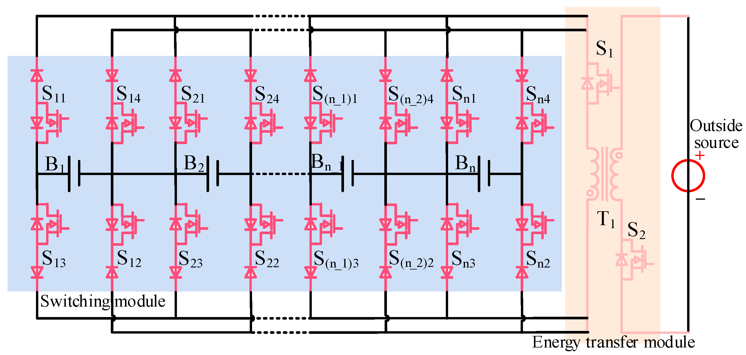
2.1. Structure of the Proposed Equalizer

Figure 1 shows the structure of the proposed equalizer. The proposed equalizer comprises a switch module, an energy transfer module, and an outside source. The switching module consists of 4n diodes and 4n MOSFETs. Its function is to connect one cell that needs to be balanced to the energy transfer module. After the cell needing to be balanced has been connected to the energy transfer module by the operation of the switching module, the energy transfer module consisting of two MOSFETs and a transformer will be operational. It is responsible for the energy transfer. The outside source is a battery module consisting of two cells, serving as a relay station. The redundant energy in overcharged cells is first transferred into the outside source and then transferred into undercharged cells, which greatly simplifies the control strategy of the proposed equalizer.

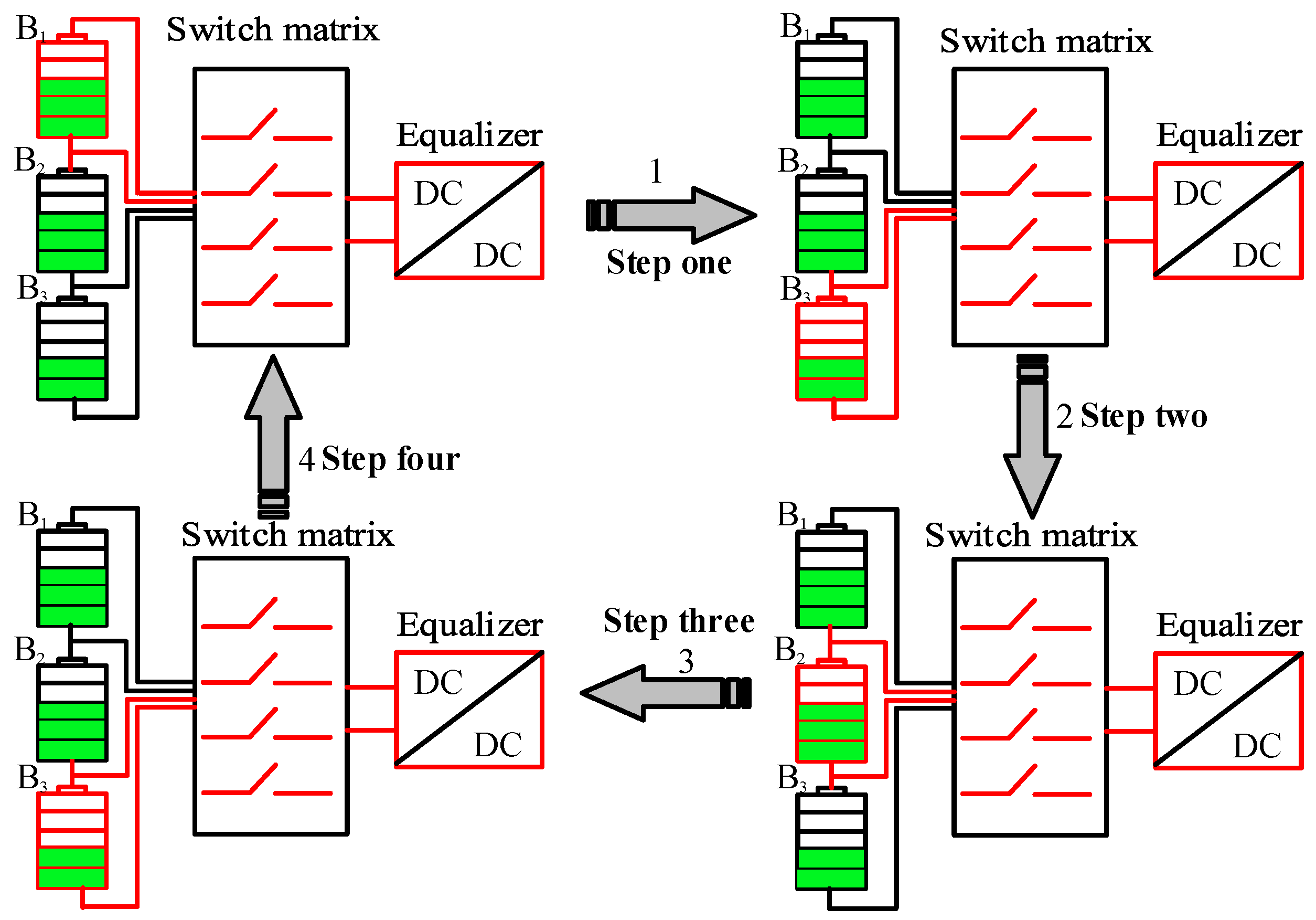
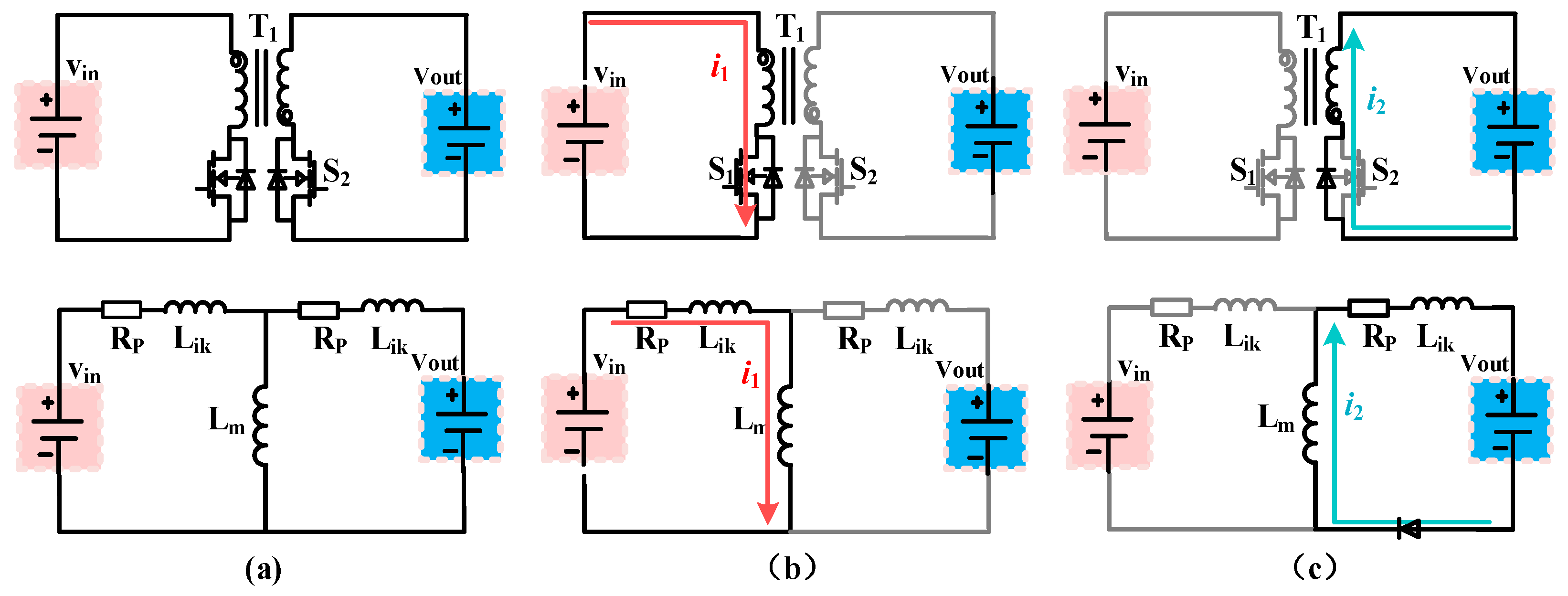
2.2. Working Principles of the Proposed Equalizer

The principle of working modes of the proposed equalizer will be illustrated in this section. The case of a string consisting of four cells is used as an example.

2.2.1. Principle of the I2O Mode

The excess energy in overcharged cells will be transferred to the outside source when the equalizer works in the I2O mode. Assuming the overcharged cells are B 1   and B 4 , and B 1 ’s voltage is highest, B 1 will be therefore firstly selected by the switching module, namely, MOSFET switches S 11 and S 12 are turned on. Next, the energy transfer module will transfer the excess energy in B 1 into the outside source. The energy transfer module can be seen as a fly-back converter, and it has two steady operation states in each switching period: state I and state II.
State I [ t 0 t 1 ]: At t = t 0 , MOSFET switch S 1 is turned on, as shown in Figure 2a. In the state, transformer T 1 stores energy from B 1 . Current i 1 increases linearly from zero and can be expressed as
i 1 = V B 1 L m t t 0
State II [ t 1 t 2 ]: At t = t 1 , MOSFET switch S 1 is turned off, and then the body diode of S 2 forward bias, as shown in Figure 2b. In this state, transformer T 1 releases the energy from B 1 , and current i 1 decreases linearly from its initial value I 1 m a x which can be calculated by
I 1 m a x = V B 1 L m t 1 t 0 = V B 1 L m D T
where L m is the inductance of the excitation inductor of the fly-back transformer used, D is the duty cycle, and T is the switching period.
Current i 1 can be expressed as
i 1 = I 1 m a x V O L m t t 1 = V B 1 L m D T V O L m t t 1
where V O is the voltage of the outside source.
The switching module will connect B 4 to the energy transfer module and transfer the excess energy in B 4 to the outside source, when B 1 ’s voltage equals the average voltage. The excess energy in B 4 will also be transferred into the outside source in the same way as described before. Current i 4 can be expressed as
i 4 = V B 4 L m ( t t 0 )  
And current i 4 can be expressed as
i 4 = V B 4 L m D T V O L m t t 1

2.2.2. Principle of O2I Mode

Energy in the outside source will be transferred to undercharged cells when the equalizer works in the I2O mode. Assuming the undercharged cells are B 2   and B 3 , and B 3 ’s voltage is higher than B 2 ’s. Therefore, B 2 will be firstly selected by the switching module, namely MOSFET switches S 23 and S 24 are turned on. Next, the energy transfer module will transfer energy from the outside source to B 2 . When working in the O2I mode, the energy transfer module has two steady states in each switching period: state I and state II.
State I [ t 0 t 1 ]: At t = t 0 , MOSFET switch S 2 is turned on, as shown in Figure 3a. In this state, transformer T 1 stores energy from the outside source. Current i 2 increases linearly from zero and can be expressed as
i 2 = V O L m t t 0
State II [ t 1 t 2 ]: At t = t 1 , MOSFET switch S 2 is turned off, and then diodes aside MOSFET switches S 23 and S 24 forward bias, as shown in Figure 3b. In this state, transformer T 1 releases the energy from the outside source. Current i 2 decreases linearly from its initial value I 2 m a x which be calculated by
I 2 m a x = V O L m t 1 t 0 = V O L m D T
And current i 2 can be written as
i 2 = I 2 m a x V O L m t t 1 = V O L m D T V B 2 L m t t 1  
When B 2 ’s voltage equals the average voltage, the switching module will connect B 3 to the energy transfer module which will transfer energy from the outside source to B 3 . Since the working states of the energy transfer module is the same as when B 2 is selected, analysis of it is omitted here. Current i 3 can be expressed as
i 3 = V O L m ( t t 0 )
And current i 3 can be expressed as
i 3 = V O L m D T V B 3 L m t t 1

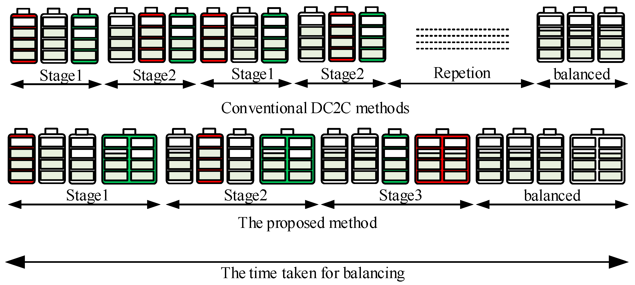
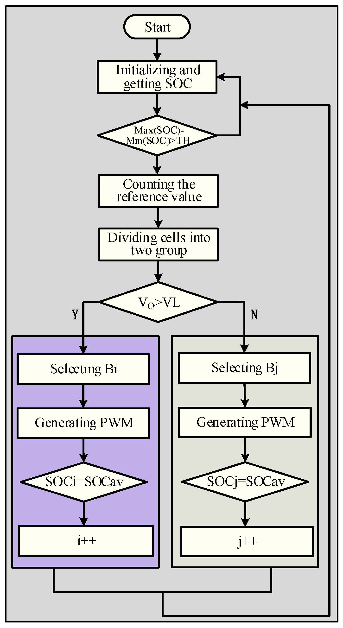
2.3. Balancing Strategy of the Proposed Equalizer

Before explaining the proposed equalizer’s control strategy, the function of the outside source consisting of two cells and the reason for using it will be presented first. For most equalizers of the category of the DC2C method, it is a common thing that the unavoidably repeated actions of the switch matrix when the number of cells with the highest state-of-charge (SOC) did not equal 1, namely more than one cell with the highest SOC. For example, a string consisting of three cells is equipped with an equalizer belonging to the DC2C method as shown in Figure 4. When B 1 and B 2 are overcharged, and their SOCs are the same, the switching matrix needs to continually switch between B 1 and B 2 to make sure   B 1 and B 2 still have the same SOC during balancing. This will bring unwanted switching loss. There is an outside source in the proposed scheme to solve this issue. As shown in Figure 5, the outside source can be used as a transfer station which can store the excess energy in overcharged cells. Namely, the energy can be retransferred to the undercharged cells after the excessive energy in overcharged cells is completely collected by the outside source. Therefore, the number of actions of the switch matrix and the degree of complication of control is greatly reduced due to the existence of the outside source.
The difference in the balancing process between the proposed method and the conventional DC2C method is shown in Figure 6. Therein, the battery being charged is marked with green, and the battery being discharged is marked with green. It can be seen from Figure 6 that there are three stages in the balancing process of the proposed equalizer and several stages in the balancing process of conventional D2C2 methods. Therefore, the switching loss is greatly reduced in the proposed scheme.
The flowchart of control strategy of the proposed equalizer is shown in Figure 7. First, the average value of SOC of cells is used as the reference value, and all cells in the battery string will be divided into two groups. One group contains overcharged cells, and another group contains undercharged cells. Second, according to the voltage of the outside source, the equalizer will work in the I2O mode or I2O mode. If the voltage of the outside source does not reach the predetermined upper limit, the equalizer will work in the I2O mode. When operating in this mode, the equalizer transfers energy from overcharged cells into the outside source sequentially. If the voltage of the outside reaches the predetermined upper limit, the equalizer switches into the O2I mode. When operating in this mode, the equalizer transfers energy from the outside source into the undercharged cells sequentially. Finally, if all cell’s SOCs equal the reference value, the equalizer will stop working, which means the end of equalization.

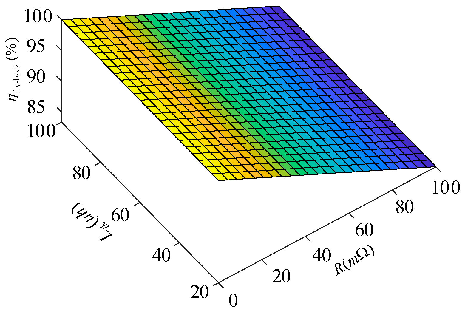
2.4. Efficiency Analysis

The balancing efficiency is an important performance index of an equalizer. Therefore, it is necessary to analyze the balancing efficiency of an equalizer to ensure its validity.
During the process of equalization of the proposed equalizer, the loss will inevitably occur due to the existence of parasitic resistance in the wires and the turn-on resistance of MOSFETs. The energy transfer module of the proposed equalizer can be seen as a fly-back DC-DC converter (FBDDC). For an FBDDC, energy loss includes leakage inductance loss, switch conducting loss, and primary and secondary winding loss [19].
The equivalent circuits of the proposed equalizer are shown in Figure 8. Each switch period includes two stages: the charging stage and the discharging stage. Assuming the V i n   and V o u t are the input and out voltage of the equalizer, respectively. At the end of the charging stage, the maximum current through the primary winding of the transformer is
I 1 m a x = D V i n f ( L m + L ik )
where L m   is the magnetic inductance of the transformer used, and L ik is the leakage inductance of the transformer used.
The loss occurring in the charging stage is represented by P R . P R   is caused by the parasitic resistance that is the sum of the turn-on resistance and the primary winding resistance. It can be expressed as
P R = i 1 r m s 2 R P = 1 3 D R P i 1 m a x 2 = D 3 V i n 2 R P 3 f 2 ( L m + L ik ) 2
where R P is the parasitic resistance, i 1 r m s is the RMS of the current though the primary winding of the transformer, and D is the duty cycle.
The loss occurring in the discharging stage is represented by P R , which is caused by the parasitic resistance that is the sum of the turn-on resistance and the secondary winding resistance, and it can be expressed as
P R = 1 3 ( 1 D ) R P i 1 m a x 2 = ( 1 D ) 3 V o u t 2 V d 2 R P 3 f 2 ( L m + L ik ) 2
where V d is the forward voltage of diodes.
The loss caused by the leakage inductance is represented by P ik , and it can be expressed as
P ik = 2 3 i 1 m a x 2 = 2 D 3 V i n 2 L i k 3 L m 2 f
Therefore, the efficiency of the proposed equalizer can be calculated by
η fly - back = P i n P l o s s P i n = P i n ( P R + P R + P ik ) P i n
Finally, the efficiency curve of the proposed equalizer is shown in Figure 9. According to it, the balancing efficiency of the proposed equalizer rises with the decrease in leakage inductance and parasitic resistance.

3. Design Consideration

Paramenter Design

In the application of equalization, the main consideration of designing a transformer is the current gain rather than the voltage gain [7]. Therefore, the turn radio of the transformer is usually set to 1. Consequently, the duty cycle of the energy transfer module can be calculated by
D = V o u t V o u t + V i n
And to assure efficiency, the energy transfer module is designed to work in the discontinued current mode [6]. Therefore, D should meet the condition of
D   V B m i n V B m i n + V B m a x
where V B m i n is the minimum voltage of the battery, and V B m a x is the maximum voltage of the battery.
Finally, the only parameter that still needs to be calculated in the proposed scheme is the magnetic inductance of transformers. Based on Equation (1), the maximum balancing current through the battery is determined by the switching frequency and the magnetic inductance of transformers. In practice, the maximum charging current is less than the maximum discharging current for batteries, and the maximum balancing current should not exceed the maximum charging current [10]. Therefore, the balancing current should meet the condition of
I B m a x = D V B m a x f ( L m + L ik ) < I C
where I B m a x is the maximum balancing current, and I C is the maximum charging current.
And drive from it, the value of the magnetic inductance of transformers should meet the condition of
L m > D V B m a x f I C L ik

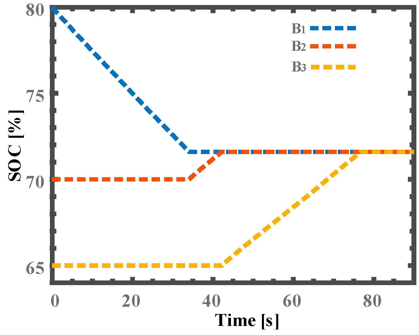
4. Simulation Results

A simulation has been carried out to verify the feasibility of the proposed equalizer. The model and the corresponding parameters used for the simulation are shown in Figure 10. Three batteries with 0.1 AH are used for the simulation to shorten the simulation time.
The simulation results of the three cells are illustrated in Figure 11. The balancing processes last about 80 s and all SOCs of the cells are balanced. Therefore, the simulation verifies the feasibility of the proposed equalizer.

5. Experiment and Comparison
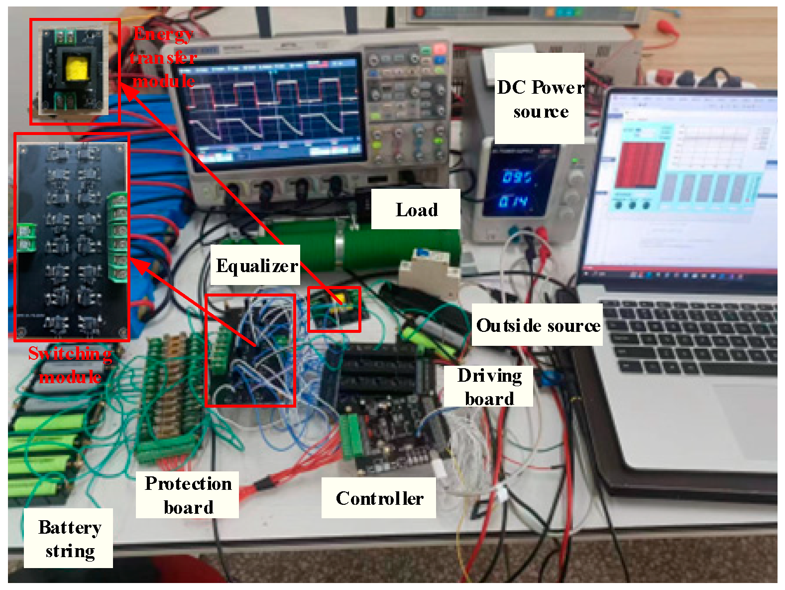
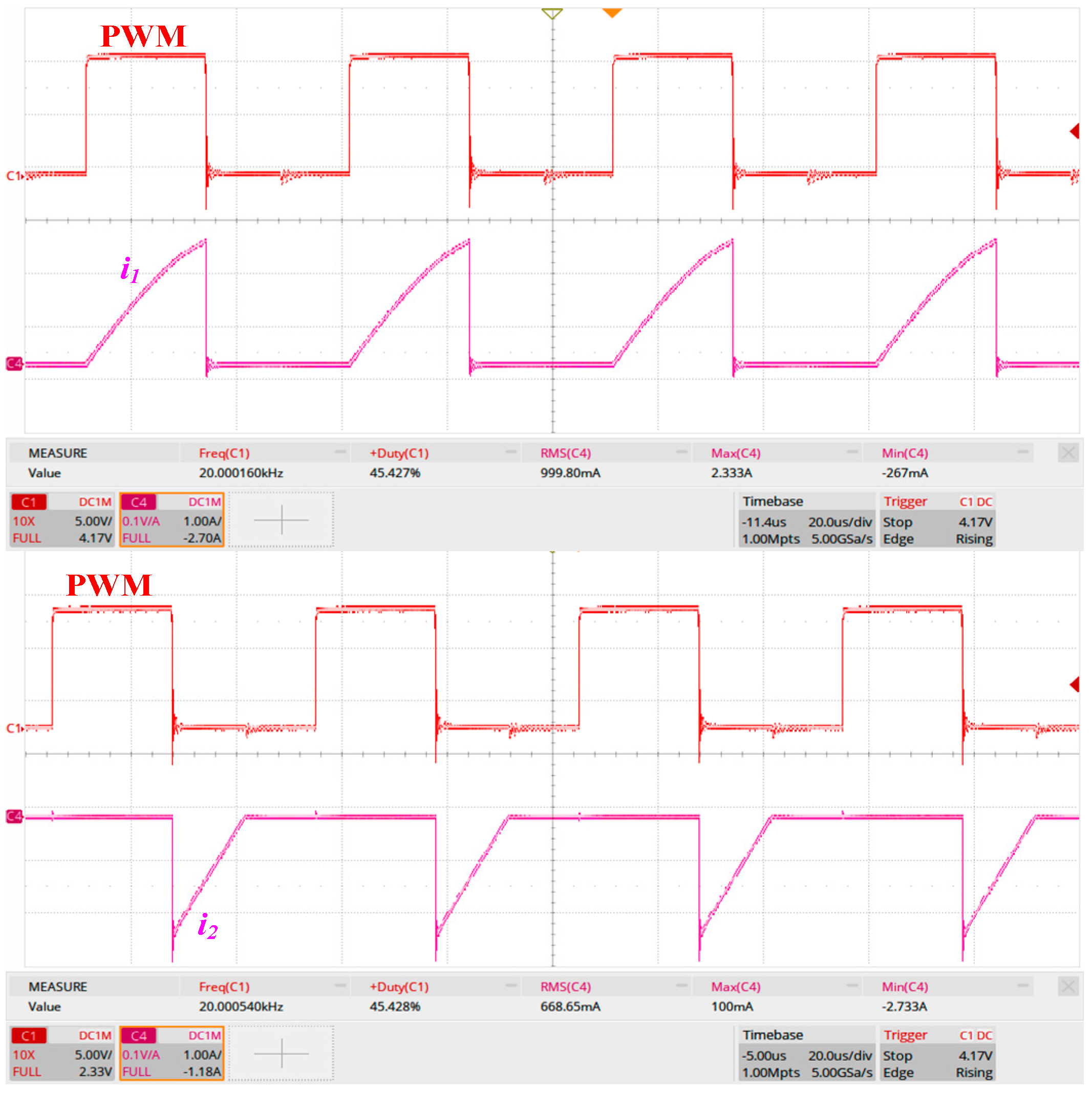
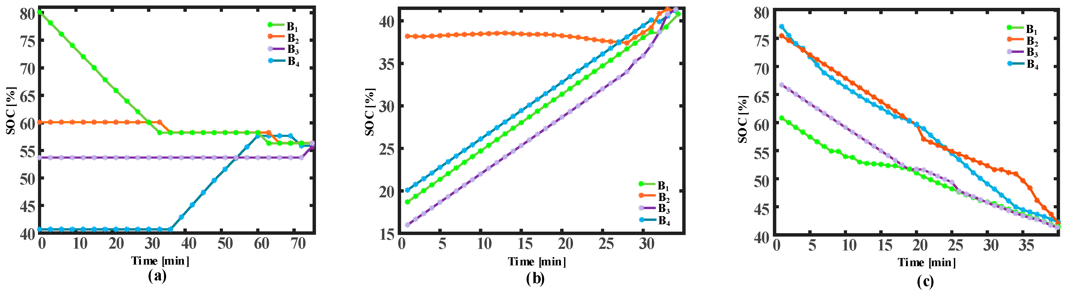
5.1. Experiment

To demonstrate the feasibility of the proposed equalizer, a prototype for four lithium-ion cells connected in a series was implemented, and the corresponding parameters used for the experiment are summarized in Table 1.
The platform used for the experiment is shown in Figure 12. The platform used for the experiment includes a load, a battery string, the proposed equalizer, a controller, and a computer. The current and voltage data are recorded by the controller, and the controller sends the data to the computer. Based on the received current and voltage data, the computer estimates the SOCs of cells and sends it back to the controller, and the controller will take action according to the received SOCs of cells.
Figure 13 shows the key waves of the proposed equalizer. Therein, PWM is the control sign for the S1, i 1 is the current through the primary winding of the transformer, and i 2 is the current through the secondary winding of the transformer.
The experiment results are demonstrated graphically in Figure 14. Figure 14a–c show the equalization results for the battery string under different working conditions, respectively. The equalization results for the battery string under the rest condition are shown in Figure 14a. It can be seen that the equalization ends after about 74 min, and the maximum gap between SOCs decreases to less than 1%. Similarly, from Figure 14b,c, it can be seen that the maximum gap between SOCs decreases to less than 1% after about 30 min and 40 min, respectively. Based on the experiment results, it can be concluded that the proposed equalizer works well in real applications.

5.2. Comparison Study

In order to give a systematical evaluation of the proposed scheme, a comparison between some methods and the proposed one is summarized in Table 2. Therein, assuming the number of cells is n, comparative terms include the number of components and performance indexes. The components taken into account include resistors (R), transformers (T), inductors (L), capacitors (C), switches (S), and diodes (D). The performance index consists of six parameters: implementation feasibility (P1), reliability (P2), balancing speed (P3), modularity (P4), size (P5) and mass (P6). Implementation feasibility is evaluated by the degree of complication of the control strategy used by equalizers. Reliability is evaluated by the control method of the energy transfer unit used for each scheme. The balancing speed is determined by the magnitude of the balancing current. Size is indirectly evaluated according to the number of large components in equalizers. Mass is evaluated according to the sum of the number of components used for each scheme. Each parameter can be fuzzified into five fuzzy scales, for which “1”, “2”, “3”, “4”, and “5” represent the worst, bad, neutral, good, and best performances, respectively.
The cost for each scheme cannot be calculated accurately due to difficulties in getting the price of components used by each scheme. Therefore, the cost is generally calculated by the sum of the number of components used in each scheme [2]. However, different components have different costs. Therefore, the number of each type of component will be multiplied by a weight factor, in this work. The cost of each type of component decides the weight factor for each component. The weight factors of each type of component are shown in Figure 15.
Finally, the comparison results for the cost are presented in Table 3. The results demonstrate that the proposed equalizer has a satisfactory cost.

6. Discussion

This work proposes an equalizer belonging to the DC2C method with a more uncomplicated control strategy than traditional DC2C methods. The main challenge in this reach is to write an effective balancing strategy and obtain the proper initialization of the controller’s general-purpose input and output (GPIO) ports. The simple control strategy which the equalizer has enables the proposed equalizer to avoid repeated actions of the switch matrix. Therefore, there is less of the switch loss in the proposed scheme. The control complexity and structure of an equalizer decide the reliability of an equalizer. The proposed equalizer achieves equalization with an open-loop control method and does not need a complex control strategy, which means the reliability of the proposed equalizer is standable. The control strategy with simplicity is the feature of the proposed scheme, but the proposed scheme still has some disadvantages. For example, the efficiency of the proposed equalizer could be higher. Such as adding an active clamp circuit to the energy transfer module and introducing the soft switching technology, and this is possible improvement aimed for in future work.

7. Conclusions

An equalizer with multi modes is designed for the problem of inconsistency in battery strings in this paper. The working principle of the proposed equalizer is presented first. The efficiency analysis and design consideration, and simulation for the proposed follows to serve the experiment. And the experimental results show that the introduction of the outside source in the proposed scheme can simplify the balancing strategy for the proposed equalizer remarkably. Therefore, the proposed equalizer has a control method with simplicity, and unnecessary actions of the switch matrix are also avoided in the proposed equalizer. Furthermore, the number of high-priced components used to build the equalizer, such as transformers and MOSFETs, is low in the proposed scheme, which boosts the feasibility of the proposed scheme. Finally, the comparison between the proposed equalizer and the others is conducted to verify the merits of the proposed equalizer in terms of costs and size.

Author Contributions

Conceptualization, H.L.; methodology, H.L.; software, X.Y.; validation, X.W.; formal analysis, H.L.; investigation, J.A.; resources, X.W.; writing—original draft preparation, J.A.; writing—review and editing, X.Y. and J.A.; supervision, H.L. All authors have read and agreed to the published version of the manuscript.

Funding

This work is supported by National Natural Science Foundation of China (51967009).

Data Availability Statement

Data are contained within the article.

Conflicts of Interest

The authors declare no conflict of interest.

References

  1. Gallardo-Lozano, J.; Romero-Cadaval, E.; Milanes-Montero, M.I.; Guerrero-Martinez, M.A. Battery equalization active methods. J. Power Sources 2014, 246, 934–949. [Google Scholar]
  2. Daowd, M.; Omar, N.; Bossche, P.V.D.; Van Mierlo, J. Passive and active battery balancing comparison based on MATLAB simulation. In Proceedings of the 2011 IEEE Vehicle Power and Propulsion Conference, Chicago, IL, USA, 6–9 September 2011; IEEE: Piscataway, NJ, USA. [Google Scholar]
  3. Lu, S.; Yin, Z.; Liao, S.; Yang, B.; Liu, S.; Liu, M.; Yin, L.; Zheng, W. An Asymmetric Encoder–Decoder Model for Zn-Ion Battery Lifetime Prediction. Energy Rep. 2022, 8, 33–50. [Google Scholar]
  4. Huang, Z.; Luo, P.; Zheng, H.; Lyu, Z.; Ma, X. Novel one-dimensional V3S4@NC nanofibers for sodium-ion batteries. J. Phys. Chem. Solids 2023, 172, 111081. [Google Scholar]
  5. Kim, C.-H.; Kim, M.-Y.; Park, H.-S.; Moon, G.-W. A Modularized Two-Stage Charge Equalizer with Cell Selection Switches for Series-Connected Lithium-Ion Battery String in an HEV. IEEE Trans. Power Electron. 2012, 27, 3764–3774. [Google Scholar] [CrossRef]
  6. Conway, T. An Isolated Active Balancing and Monitoring System for Lithium Ion Battery Stacks Utilizing a Single Transformer Per Cell. IEEE Trans. Power Electron. 2021, 36, 3727–3734. [Google Scholar]
  7. Anno, T.; Koizumi, H. Double-Input Bidirectional DC/DC Converter Using Cell-Voltage Equalizer with Flyback Transformer. IEEE Trans. Power Electron. 2014, 30, 2923–2934. [Google Scholar]
  8. Peng, F.; Wang, H.; Wei, Z. An LLC-Based Highly Efficient S2M and C2C Hybrid Hierarchical Battery Equalizer. IEEE Trans. Power Electron. 2019, 35, 5928–5937. [Google Scholar]
  9. Kim, M.-Y.; Kim, J.-H.; Moon, G.-W. Center-Cell Concentration Structure of a Cell-to-Cell Balancing Circuit with a Reduced Number of Switches. IEEE Trans. Power Electron. 2013, 29, 5285–5297. [Google Scholar]
  10. Fan, S.; Duan, J.; Sun, L.; Zhang, K. A Fast Modularized Multiwinding Transformer Balancing Topology for Series-Connected Super Capacitors. IEEE Trans. Power Electron. 2018, 34, 3255–3268. [Google Scholar] [CrossRef]
  11. Shang, Y.; Cui, N.; Duan, B.; Zhang, C. A Global Modular Equalizer Based on Forward Conversion for Series-Connected Battery Strings. IEEE J. Emerg. Sel. Top. Power Electron. 2017, 6, 1456–1469. [Google Scholar]
  12. Wang, Y.; Zhang, C.; Chen, Z.; Xie, J.; Zhang, X. A novel active equalization method for lithium-ion batteries in electric vehicles. Appl. Energy 2015, 145, 36–42. [Google Scholar]
  13. Li, Y.; Xu, J.; Mei, X.; Wang, J. A Unitized Multiwinding Transformer-Based Equalization Method for Series-Connected Battery Strings. IEEE Trans. Power Electron. 2019, 34, 11981–11989. [Google Scholar] [CrossRef]
  14. Kim, M.-Y.; Kim, C.-H.; Kim, J.-H.; Moon, G.-W. A Chain Structure of Switched Capacitor for Improved Cell Balancing Speed of Lithium-Ion Batteries. IEEE Trans. Ind. Electron. 2013, 61, 3989–3999. [Google Scholar] [CrossRef]
  15. Ding, X.; Zhang, D.; Cheng, J.; Wang, B.; Chai, Y.; Zhao, Z.; Xiong, R.; Luk, P.C.K. A Novel Active Equalization Topology for Series-Connected Lithium-ion Battery Packs. IEEE Trans. Ind. Appl. 2020, 56, 6892–6903. [Google Scholar]
  16. Shang, Y.; Zhang, C.; Cui, N.; Mi, C. A Delta-Structured Switched-Capacitor Equalizer for Series-Connected Battery Strings. IEEE Trans. Power Electron. 2018, 34, 452–461. [Google Scholar] [CrossRef]
  17. Shang, Y.; Xia, B.; Lu, F.; Zhang, C.; Cui, N.; Mi, C.C. A Switched-Coupling-Capacitor Equalizer for Series-Connected Battery Strings. IEEE Trans. Power Electron. 2016, 32, 7694–7706. [Google Scholar]
  18. Shang, Y.; Cui, N.; Duan, B.; Zhang, C. Analysis and Optimization of Star-Structured Switched-Capacitor Equalizers for Series-Connected Battery Strings. IEEE Trans. Power Electron. 2017, 33, 9631–9646. [Google Scholar] [CrossRef]
  19. Xiong, H.; Fu, Y.; Dong, K. A Novel Point-to-Point Energy Transmission Voltage Equalizer for Series-Connected Supercapacitors. IEEE Trans. Veh. Technol. 2015, 65, 4669–4675. [Google Scholar] [CrossRef]
  20. Lee, K.-M.; Lee, S.-W.; Choi, Y.-G.; Kang, B. Active Balancing of Li-Ion Battery Cells Using Transformer as Energy Carrier. IEEE Trans. Ind. Electron. 2016, 64, 1251–1257. [Google Scholar] [CrossRef]
  21. Chen, Y.; Liu, X.; Cui, Y.; Zou, J.; Yang, S. A Multi-winding Transformer Cell-to-Cell Active Equalization Method for Lithium-Ion Batteries with Reduced Number of Driving Circuits. IEEE Trans. Power Electron. 2015, 31, 4916–4929. [Google Scholar]
  22. Park, S.-H.; Park, K.-B.; Kim, H.-S.; Moon, G.-W.; Youn, M.-J. Single-Magnetic Cell-to-Cell Charge Equalization Converter with Reduced Number of Transformer Windings. IEEE Trans. Power Electron. 2011, 27, 2900–2911. [Google Scholar] [CrossRef]
  23. Xu, B.; Yan, Z.; Xiong, L.; Zhang, L.; Zhou, W.; Mai, R.; He, Z.; Liu, L. A Double-Switch Single-Transformer Integrated Equalizer for the Recycled Power Battery String of Automatic Guided Vehicles. IEEE Trans. Ind. Electron. 2023, 70, 2596–2606. [Google Scholar] [CrossRef]
  24. Liu, L.; Mai, R.; Xu, B.; Sun, W.; Zhou, W.; He, Z. Design of Parallel Resonant Switched-Capacitor Equalizer for Series-Connected Battery Strings. IEEE Trans. Power Electron. 2021, 36, 9160–9169. [Google Scholar] [CrossRef]
  25. Wei, Z.; Wang, H.; Lu, Y.; Shu, D.; Ning, G.; Fu, M. Bidirectional Constant Current String-to-Cell Battery Equalizer Based on L2C3 Resonant Topology. IEEE Trans. Power Electron. 2022, 38, 666–677. [Google Scholar] [CrossRef]
  26. Zhou, G.; Zhang, X.; Gao, K.; Tian, Q.; Xu, S. Two-Mode Active Balancing Circuit Based on Switched-Capacitor and Three-Resonant-State LC Units for Series-Connected Cell Strings. IEEE Trans. Ind. Electron. 2021, 69, 4845–4858. [Google Scholar] [CrossRef]
  27. Shang, Y.; Zhang, Q.; Cui, N.; Duan, B.; Zhang, C. An Optimized Mesh-Structured Switched-Capacitor Equalizer for Lithium-Ion Battery Strings. IEEE Trans. Transp. Electrific. 2019, 5, 252–261. [Google Scholar] [CrossRef]
  28. Liu, K.; Yang, Z.; Tang, X.; Cao, W. Automotive Battery Equalizers Based on Joint Switched-Capacitor and Buck-Boost Converters. IEEE Trans. Veh. Technol. 2020, 69, 12716–12724. [Google Scholar] [CrossRef]
  29. La, P.-H.; Choi, S.-J. Direct Cell-to-Cell Equalizer for Series Battery String Using Switch-Matrix Single-Capacitor Equalizer and Optimal Pairing Algorithm. IEEE Trans. Power Electron. 2022, 37, 8625–8639. [Google Scholar] [CrossRef]
  30. Shang, Y.; Cui, N.; Zhang, C. An Optimized Any-Cell-to-Any-Cell Equalizer Based on Coupled Half-Bridge Converters for Series-Connected Battery Strings. IEEE Trans. Power Electron. 2018, 34, 8831–8841. [Google Scholar] [CrossRef]
  31. Zou, R.; Liu, F.; Liu, Y.; Xu, G.; Liu, F. An LLC-Based Battery Equalizer with Inherent Current Limitation. IEEE Trans. Power Electron. 2021, 37, 1828–1840. [Google Scholar] [CrossRef]
  32. Shang, Y.; Xia, B.; Zhang, C.; Cui, N.; Yang, J.; Mi, C.C. An Automatic Equalizer Based on Forward–Flyback Converter for Series-Connected Battery Strings. IEEE Trans. Ind. Electron. 2017, 64, 5380–5391. [Google Scholar] [CrossRef]
  33. Shang, Y.; Xia, B.; Zhang, C.; Cui, N.; Yang, J.; Mi, C. A Modularization Method for Battery Equalizers Using Multiwinding Transformers. IEEE Trans. Veh. Technol. 2017, 66, 8710–8722. [Google Scholar] [CrossRef]
  34. Moghaddam, A.F.; Van den Bossche, A. A Ćuk Converter Cell Balancing Technique by Using Coupled Inductors for Lithium-Based Batteries. Energies 2019, 12, 2881. [Google Scholar] [CrossRef]
  35. Wang, K.; Ke, J.; Zhan, M.; Tian, A.; Wu, T.; Zhang, X.; Jiang, J. Efficient and Fast Active Equalization Method for Retired Battery Pack Using Wide Voltage Range Bidirec-tional Converter and DBSCAN Clustering Algorithm. IEEE Trans. Power Electron. 2022, 37, 13824–13833. [Google Scholar]
  36. Hasanpour, N.; Khajehoddin, S.A. Energy Conservation Versus Charge Conservation Law for Modeling and Analyzing Cell Equalizers. IEEE Trans. Power Electron. 2023, 38, 14638–14651. [Google Scholar] [CrossRef]
Figure 1. Structure of the proposed equalizer.
Electronics 12 04521 g001
Figure 2. I2O mode. (a) state I for B 1 (b) state II for B 1 (c) state I for B 4 (d) state II for B 4 .
Electronics 12 04521 g002
Figure 3. O2I mode. (a) state I for B 2 (b) state II for B 2 (c) state I for B 3 (d) state II for B 3 .
Electronics 12 04521 g003
Figure 4. Case of traditional DC2C methods.
Electronics 12 04521 g004
Figure 5. Case of the proposed DC2C method with an outside source.
Electronics 12 04521 g005
Figure 6. Discrepancy between the proposed method and conventional D2C2 methods.
Electronics 12 04521 g006
Figure 7. Control strategy of the proposed equalizer.
Electronics 12 04521 g007
Figure 8. Equivalent circuit of the proposed equalizer in one switch period. (a) Equivalent circuit (b) Equivalent circuit during charging stage (c) Equivalent circuit during discharging stage.
Electronics 12 04521 g008
Figure 9. Efficiency curve of the proposed equalizer.
Electronics 12 04521 g009
Figure 10. Simulation circuit of the proposed equalizer.
Electronics 12 04521 g010
Figure 11. Simulation results for the proposed equalizer.
Electronics 12 04521 g011
Figure 12. Platform used for the experiment.
Electronics 12 04521 g012
Figure 13. Key waves of the proposed equalizer.
Electronics 12 04521 g013
Figure 14. Results of the experiment: (a) balancing result under the rest condition, (b) balancing result under the charging condition, (c) balancing result under the discharging condition.
Electronics 12 04521 g014
Figure 15. Weight factors of each type of component.
Electronics 12 04521 g015
Table 1. Experiment parameters.
ParameterValue
BatteryModelLS18650-10A
Nominal capacity2600 mAh
Nominal voltage3.6 V
Internal resistance<30 mΩ
MOSFETOn-resistance16~25 mΩ
ModelNCE6080AK
DiodeForward voltage0.8~1.2 V
Transformer L m 24 μH
L i k <0.3 μh
N 1 : N 2 1:1
Wingding resistance<120 mΩ
Table 2. Comparison of several methods.
MethodsComponentsP1P2P3P4P5P6
RTLCSD
[2]n00000551045
[17]01004 n0452144
[18]01004 n0343144
[19]01004 n0443124
[6]013 n + 114 n0442132
[8]0n103 n + 10315331
[14]000n4 n0323334
This work01004 n4 n553244
Table 3. Comparison of the cost.
MethodsComponentsCost
RTLCSD
[2]n000000.05 n
[17]01004 n01.2 n + 0.3
[18]01004 n01.2 n + 0.3
[19]01004 n01.2 n + 0.3
[6]013 n + 114 n01.65 n + 0.6
[8]0n103 n + 101.2 n + 0.45
[14]0002 n4 n01.5 n
This work01004 n4 n1.4 n + 0.3
Disclaimer/Publisher’s Note: The statements, opinions and data contained in all publications are solely those of the individual author(s) and contributor(s) and not of MDPI and/or the editor(s). MDPI and/or the editor(s) disclaim responsibility for any injury to people or property resulting from any ideas, methods, instructions or products referred to in the content.

