Abstract
Continuous-wave tunable photonics-based THz sources present limited output power due to the restricted input optical power accepted by photomixers, along with reduced radiation resulting from low paraxial field amplitude. Here, we investigate multipolar antenna designs to increase the available continuous-wave THz output power by incorporating more photomixers. For this purpose, the spatial structures of the optical and THz E-fields are designed to enhance THz power and radiation in the far field. Simulations of 2 to 4 dipole antennas are conducted, demonstrating an improvement in antenna gain compared to standard dipole antennas. This is in addition to a potential increase in THz power and radiation for photomixing applications. Such work also paves the way for functionalizing the spatial structure of THz light for advanced applications.
1. Introduction
Electromagnetic waves at THz frequencies are attractive for applications such as high-data-rate wireless communications, industrial control, defence, and security. THz technologies are especially interesting for future mobile communications, as theoretical data rates of tens to hundreds of Gbps can be achieved for carrier frequencies within the atmospheric windows, for example, around 300 GHz. While multiple challenges remain for the next decade [1], THz wireless backhaul links have been identified as suitable alternatives to support the transmission of highly aggregated data from mobile nodes [2], particularly for future 6G networks [3,4,5]. Electronics-based and/or photonics-based technologies are involved in providing key components for these communication systems, such as THz sources and detectors. Recently, a purely photonic wireless link at 120 GHz has been demonstrated [6], showing the significance of photonics-based components in communication applications. THz continuous-wave sources based on photonics systems rely on mature technologies and offer exceptional tunability and modulation bandwidth. However, their main drawback is limited output power and radiation [7], mainly due to the poor optical-to-THz conversion efficiency of photomixers and significant far-field divergence outside of paraxial conditions, despite tremendous progress in uni-traveling-carrier photodiodes [8] and plasmonics-enhanced photoconductive antennas [9]. Among the possible strategies to enhance THz power, the use of photomixer arrays has recently been investigated, either using uni-traveling-carrier photodiodes [8,10,11,12,13,14] or photoconductive antennas [15]. The use of photomixer arrays is also attractive as they allow for beam steering, as reported in Refs. [16,17], and an intensity improvement can be achieved in the direction of the maximum radiation pattern, proportional to the square root of the number of photomixers [18,19]. However, to achieve an increase in THz power resulting from the combination of photomixers, one should ensure a coherent combination; this depends on the photomixer array itself as well as the optical excitation, with the latter being particularly challenging unless fully integrated systems are considered.
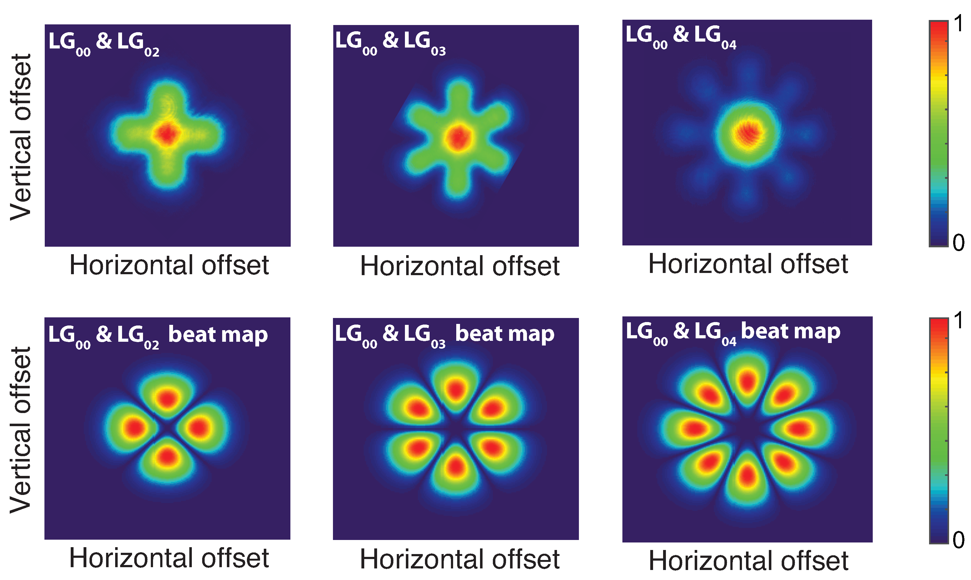
Among the possible coherent optical sources that could be used to generate the optical beating, we recently proposed using a continuous-wave, high-power, highly-coherent, tunable, dual-frequency laser. This laser is based on III-V semiconductor vertical external-cavity surface-emitting laser (VeCSEL) technology, simultaneously emitting two transverse modes operating around 1064 nm [20] in a single linear polarization state. We demonstrated coherent and tunable THz emission using two types of photomixers: a commercial uni-traveling carrier photodiode [21] and a plasmonics-based photoconductive antenna [22]. In these reported experiments, the two laser fields are intracavity, low-divergence Laguerre–Gauss (LG) modes emitting at two distinct frequencies, thus allowing for THz generation at the beat frequency through the excitation of a photomixer thanks to its non-linear response. One of the two modes is the fundamental Gaussian mode LG, while the other is a higher-order LG mode that presents zero intensity in the centre (x is the azimuthal quantum number) and an azimuthal standing wave exhibiting phase shift between successive lobes. The overlap between these transverse modes is small enough to ensure stable dual-frequency operation within the homogeneous-gain laser and is sufficient to couple significant and balanced optical power at the two frequencies. The intensity map of the calculated beat intensity is represented in Figure 1 to illustrate the available beat spots in the transverse plane at the laser output. At each transverse position, the beat intensity is the square root of the product of the intensities of the two modes. We should note that alternating electronic excitation could only be obtained at the position revealed by this beat map; no beat signal could be obtained along the optical axis. The coupling of the beat signal could be realized using a single-mode fibre placed at one of the beat map maxima, as described in [21,22], but this approach is limiting as only one beat spot among the available ones is collected by the fibre; this reduces the available THz power by a factor of , as the THz power typically scales with the square of the incoming optical power.
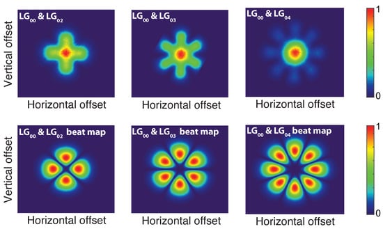
Figure 1.
Dual-frequency transverse intensity distribution. Top: Experimental intensity map observed at the output of the VeCSEL laser, showing the superposition of the fundamental mode (centre red spot) with the higher-order transverse mode (surrounding spots) for each pair of Laguerre–Gauss modes. Bottom: Calculated intensity map of the beat spots available for THz emission for different Laguerre–Gauss mode couples; each map is normalized to the maximum intensity (see colour bar for scale).
In this work, we propose a solution to improve the THz output power by taking advantage of the phase and amplitude transverse structure of the laser modes described in [20]. The idea is to collect all the optical beating spots available from the transverse Laguerre–Gauss modes of the dual-frequency VeCSEL. To this end, one could consider, for example, a uni-traveling-carrier photodiodes array or a photoconductive antenna to extract the beat signal by photomixing, but the signals generated by the multiple spots should then be radiated. By definition, a transverse mode is quite confined, so the use of an antenna array is not adequate as it would lead to strong coupling between the different elements of the array, but multipolar antennas (MPAs) [23] were considered as an opportunity to increase the THz emission power of any kind of photomixer pumped by the dual-frequency VeCSEL based on the transverse mode operation. This approach is attractive for coherent THz photonics applications in comparison to existing solutions, such as the ones reviewed in [24]. Indeed, the optical beam is intrinsically spatially and temporally coherent as it is constituted of two transverse modes from an orthogonal basis, and THz emission offers high spatial and temporal coherence [21] thanks to the pump noise and mechanical noise correlation between transverse modes that are generated within the same optical cavity with a single optical axis. Therefore, such a dual-frequency laser presents an interesting solution for tunable coherent THz combination, taking advantage of sufficiently low phase noise (close to the quantum limit) for most applications, thus avoiding the use of costly optical combs generators, and enabling possible coherent combinations without the use of alignment-sensitive optics such as micro-lens arrays [25].
2. Methods
We will first consider antennas made of perfect electrical conductors set against the vacuum background. At this stage, specifying a particular antenna substrate is unnecessary, as our investigation focuses on antenna design for specific excitation geometries derived from a particular dual-frequency laser, without considering the photo-mixer’s optical and electrical properties. While these properties are crucial for optimizing the extracted THz power and radiation of the component through careful impedance matching, this study is a fundamental step in identifying potential antenna designs and their corresponding performances. This research facilitates the identification of relevant trade-offs associated with these specific antennas, such as far-field radiation pattern, bandwidth, gain, or directivity, thus paving the way to ad hoc antenna design applied to a specific photomixer, as conducted, for example, in detail, in Refs. [26,27] for UTC photodiodes, and in Refs. [25,28,29] for a photoconductive antenna array based on a low-temperature-grown semiconductor.
2.1. CST Studio Suite Simulations
Antennas were designed and simulated using commercial 3D electromagnetic software (CST (Computer Simulation Technology) Studio Suite 2021. The time-resolution solver was used with perfect boundary approximations and the finite element method. A hexahedral mesh was considered for each simulation. To ensure convergence of the simulation, i.e., that the results of these temporal simulations are close enough to a steady state, CST performs a Fourier analysis of the time signals and compares the resulting energy of the non-DC component to the total energy inside the calculation domain. Simulations keep running as long as the energy ratio exceeds the accuracy criterion of −40 dB. The choice of this value is the result of a compromise between convergence and simulation speed, set by default by CST Studio Suite.
2.2. Multipolar Antenna Design
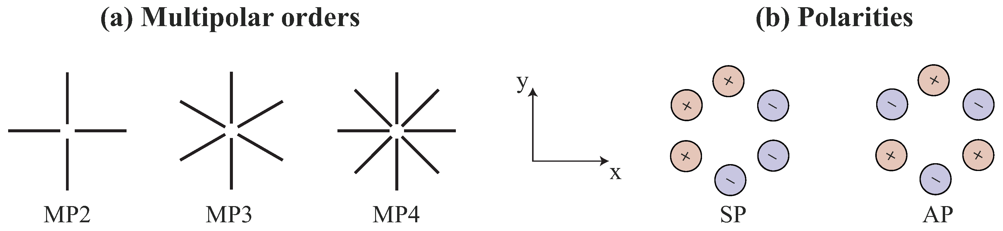
We designed multipolar antennas at 100 GHz as a proof-of-concept, with the objective of matching the specific dual-frequency E-field optical excitation that is spatially structured in both phase and amplitude. Crossed dipoles were considered, as shown in Figure 2a, consisting of 2 to 4 dipole antennas, referenced as MP2, MP3, and MP4. These could respectively be excited by LG/LG, LG/LG, and LG/LG transverse-mode pairs of the dual-frequency laser. These dipoles are placed in the (x,y) plan; therefore, the antenna is geometrically oriented in the z-direction. The gap between the arms (empty inner disk diameter) is about 80 m, and the arm width is 40 m for the MP2 and MP3 geometries, scaling down to 20 m for the MP4 to avoid overlap between arms close to the centre of the antenna. A key parameter for these antennas is the polarity of their excitation. We will study two types of polarity distribution, as shown in Figure 2b for the MP3 antenna: the super-dipole polarity (SP), which assigns a specific polarity to one half of the multipolar antenna and the opposite polarity to the other half, and the alternate polarity (AP), where the polarity alternates between neighbouring arms. The former polarity leads to a dipole-like far-field emission diagram, while the latter corresponds to the phase distribution of the high-order LG Laguerre–Gauss transverse mode of the dual-frequency laser. The inner phase of this distribution is inverted ( shifted) between neighboured lobes, leading to a phase at the origin for the beat signal that alternates between 0 and due to the LG/LG superposition.
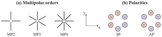
Figure 2.
Multipolar antenna designs. (a) Schematics of the antenna (not on scale) based on 2 to 4 crossed dipoles regularly distributed. For antenna simulations, the gap between arms was fixed at around 80 m, and the arm width was 40 m. (b) Two types of polarities under study for the MP3 antenna. For the super-dipole polarity (SP), one-half of the dipole arms are excited with a given polarity while the other ones are excited with the opposite polarity. For the alternate polarity (AP), polarity alternates between neighboured pins.
2.3. Multipin Port Excitation for Simulations
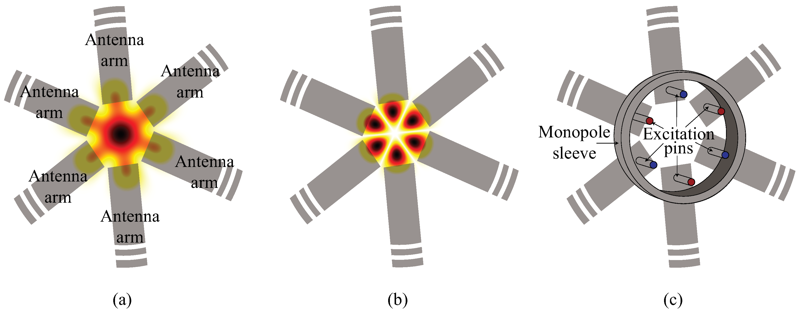
To evaluate the possible photomixing excitation consisting of multiple beat spots, a multipin input port was considered, similar to the approach proposed in Ref. [23]. The validity of the use of such a unique input port was confirmed by conducting simulations using either a biaxial input port or a discrete input port for a standard dipole antenna. As detailed in the Appendix A, these simulations provide almost identical results in terms of and far-field radiation patterns. Figure 3a presents a view of a possible MP3 antenna made of three dipoles, which is excited by the dual-frequency laser that operates on two transverse modes, LG and LG. As mentioned previously, the oscillating signal that will seed the antenna depends on the beat signal; therefore, in Figure 3b, we present a view of the resulting beat spots. Finally, the aim of this article is to evaluate the feasibility of such a possible antenna configuration by conducting simulations of the structure represented in Figure 3c, where a multipin port is connected to an MP3 antenna made of three dipoles. Similar to a coaxial cable, the hexaxial cable consists of a common monopole sleeve with six inner conductors electrically separated by vacuum spacers; each conductor is connected to one arm of the MP3 antenna. The hexaxial cable is excited by using a single waveguide port. The sleeve has a diameter of 144 m, and a height arbitrarily chosen at 45 m. The pin length is 50 m; thus, it is 5 m longer than the sleeve to avoid direct coupling between antenna arms through the sleeve. Pins are radially distributed using a radius of 55 m. Pin diameters are adjusted to maintain a cable impedance of 75 , giving 7.9 or 7.5 m, 4.6 or 3.7 m, and 2.7 or 1.7 m, respectively, for MP2, MP3, and MP4 geometries, considering SP or AP polarities. Alternate polarity requires smaller pin diameters to avoid an impedance drop due to the coupling between out-of-phase neighbour pins. The use of this multipin port is a simulation trick that allows for the simulation of the antenna with different polarity excitations, thus offering a method to evaluate the feasibility of such antennas by a primary study of possible design and related performances. Indeed, in the next section, we will show that attractive performances of the antenna are not obvious; therefore, this work paves the way for further specific designs that take into account the properties of the photomixer (including possible DC biasing), as done for other types of antenna geometries in Refs. [25,26,27,28,29].
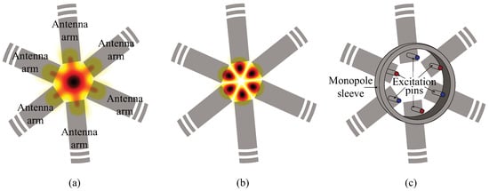
Figure 3.
Schematics of the multipolar antenna under optical excitation and the associated simulated configuration of the multipin port excitation design for MP3 geometry. (a) View of the structured laser beam arriving on the antenna (the red content corresponds to the total intensity scale, which contains two transverse modes at two different frequencies); antenna arms are not fully represented since their dimensions are very large in comparison to the beam dimension; antenna arms extend over the dashed-arms. (b) View of the generated beat signal intensity that corresponds to the THz excitation signal for the antenna. (c) View of the simulated configuration in CST, where the pin colours correspond to the excitation polarity; in this example, it demonstrates alternate polarity (AP).
3. Results
In this section, we present the simulations of multipolar antennas of different geometries (MP2, MP3, and MP4) for two kinds of excitation polarities (SP and AP). We will first study the impedance matching of these antennas and show that matching is not necessarily obtained for a standard dipole antenna with a length of , and that odd multiples of this fundamental resonance length might be required to maintain impedance matching. For these configurations, far-field patterns will be studied, and a final study of more realistic photoconductive antennas using a high-optical-index super-hemispherical lens substrate will be presented.
3.1. Impedance Matching
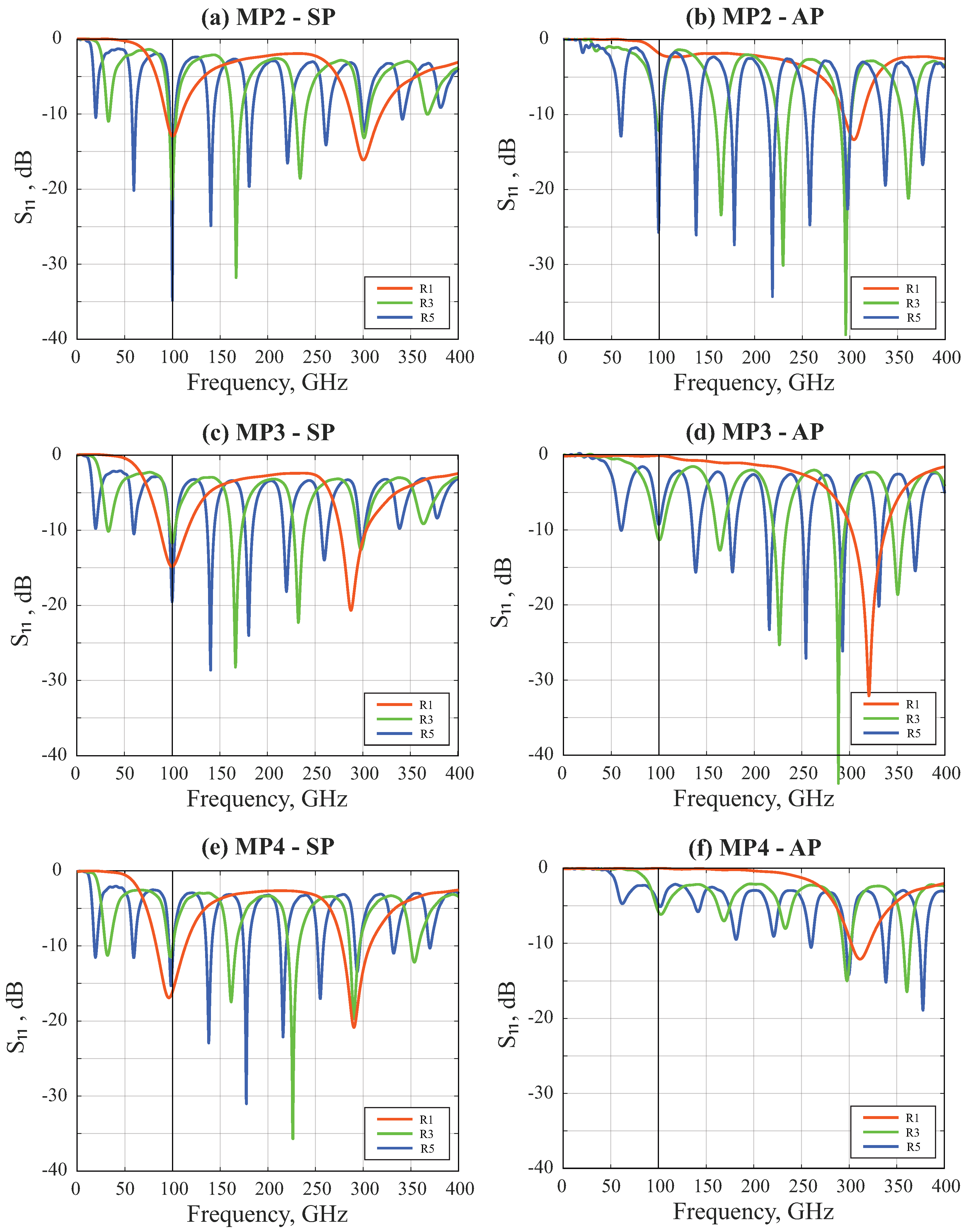
One key point concerning the antenna design is the impedance matching between the input port and the antenna. As mentioned previously, we defined a 75-ohm multipin input port by adjusting the pin diameter. Impedance matching was investigated by simulations of the parameter, as shown in Figure 4. Multipolar antenna simulations were conducted for different excitations (SP or AP) using different resonance order designs (R1, R3, R5). For each simulation, arm lengths were slightly adjusted to optimize impedance matching at 100 GHz; exact antenna dimensions are synthesized in Table 1.
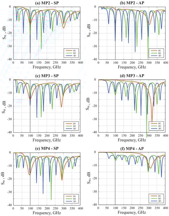
Figure 4.
S simulation of the multipolar antennas MP2−MP4, for resonance orders R1, R3, and R5.
(Left) Super-dipole multipin polarity excitation (SP). (Right) Alternate-polarity excitation (AP).

Table 1.
Key metrics at 100 GHz for different resonance designs (R1, R3, R5), different excitation polarities (SP, AP), and multipolar designs (MPs). Gain, bandwidth, and directivity are not given for unmatched-impedance antennas. FOR: First-order resonance, TOR: third-order resonance, and FiOR: fifth-order resonance.
3.2. Far-Field Patterns
Figure 5 shows the far-field patterns simulated for the different configurations. A synthesis of antenna performances is presented in Table 1, where geometric dimensions are presented for each simulation, and antenna performances are presented in terms of realized gain, directivity, and impedance-matching bandwidth at −10 dB, if available. We also compare the performances of these antennas with the one that could be obtained using a standard dipole antenna, designed at the same three resonance orders (R1, R2, R3). The key metrics of these standard dipole antennas are presented in Table 2. The pin diameter of the biaxial cable was adjusted to 13.35 m to provide a 75 impedance, and the arm length was adjusted for impedance matching at 100 GHz. These studies, using vacuum as a background, offer an intrinsic analysis of the behaviour of these multipolar antennas.

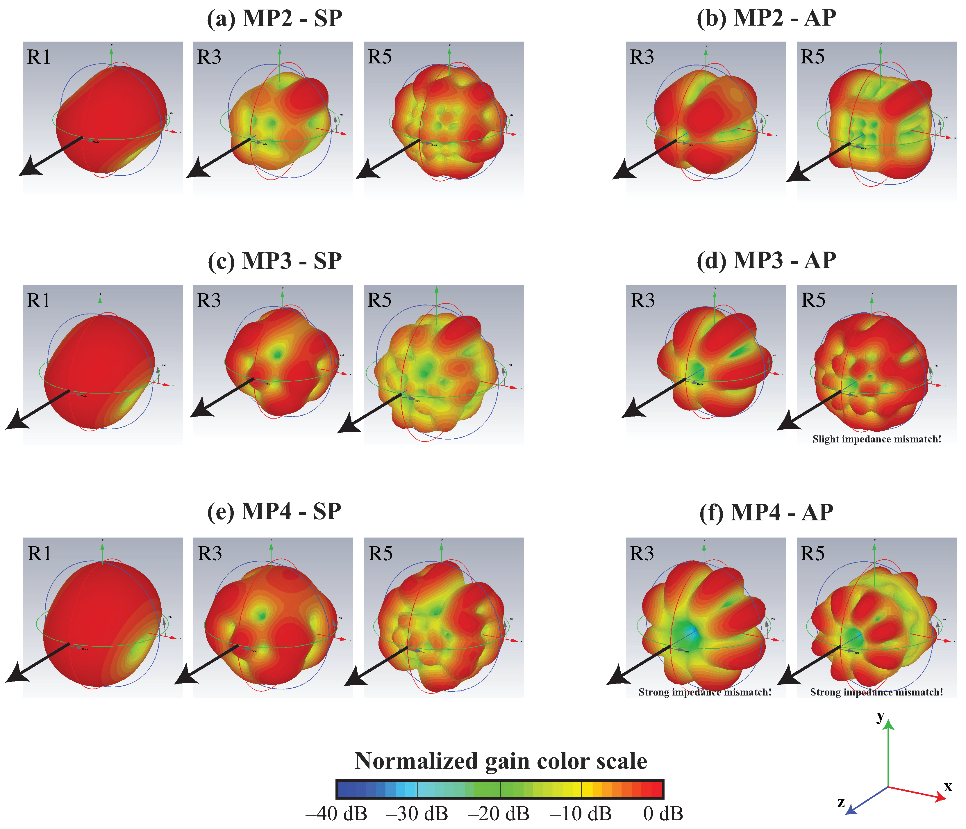
Figure 5.
Normalized far-field radiation patterns of the MP3 multipolar antenna for different polarity excitations (SP or AP) and difference resonance-order designs (R1, R3, or R5). Diagrams are simulated for emissions at 100 GHz; the gain colour scale is normalized. Diagrams for alternate polarity at the first resonance (R1) are not represented, as the antennas are not matched in terms of impedance. Some diagrams are shown for cases of slight or strong impedance mismatch (such mismatches are indicated in the figure), as they are representative of these types of antennas and could ultimately be adequate on high-index substrates.
Table 2.
Key metrics at 100 GHz for different resonance designs (R1, R3, R5) of a standard dipole antenna with multipin excitation.
3.3. Si-Lens-Coupled Antennas
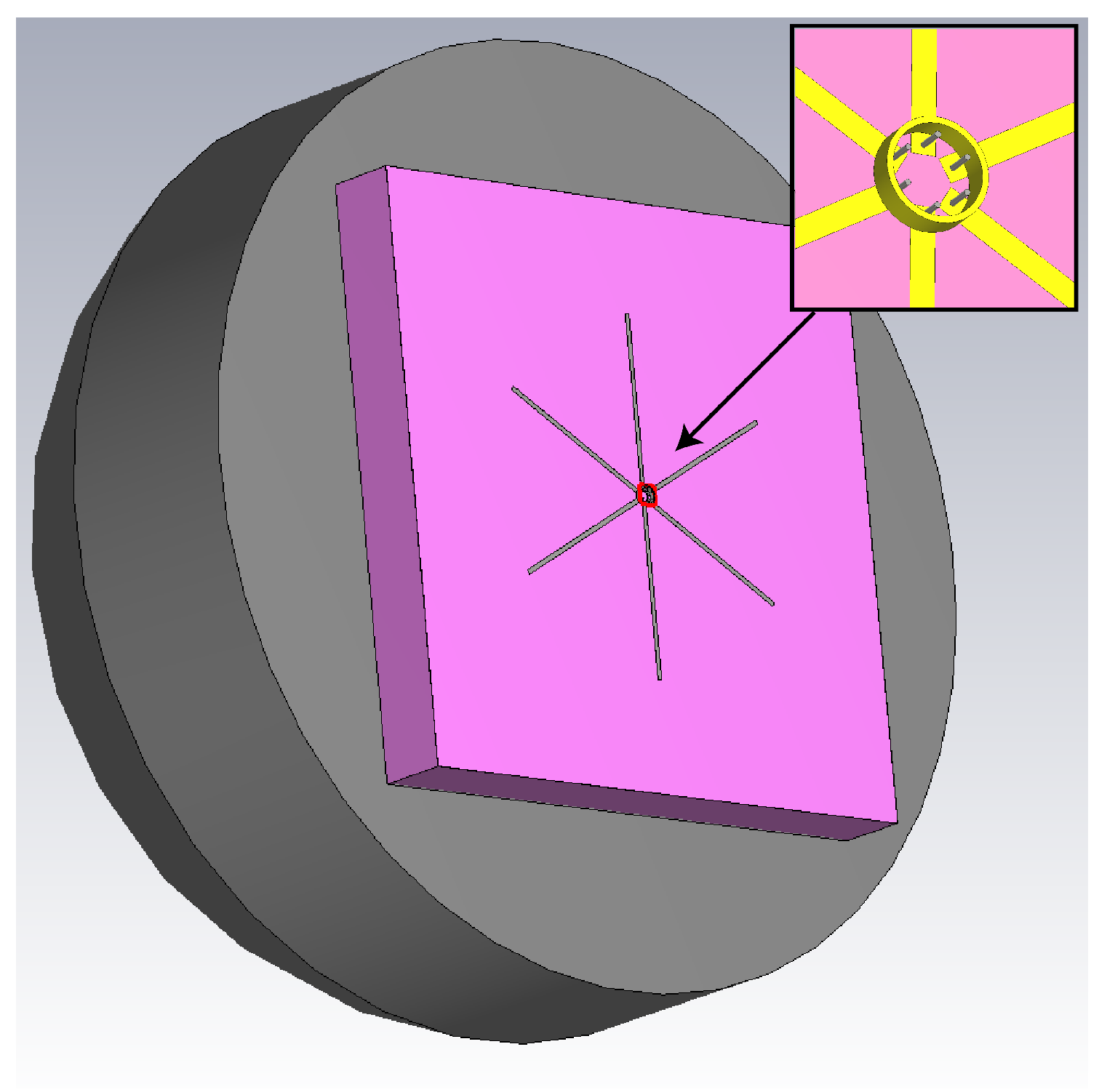
In this section, we will consider more realistic THz antennas that utilize a high-index substrate and incorporate a high-resistivity Si-lens, similar to those used in typical photoconductive antennas (as shown in Figure 6). This approach aims to improve the THz power extraction from the high-index antenna substrate, as well as improve the overall gain through collimation or at least by reducing diffraction. Therefore, we conducted simulations of multipolar antennas deposited on a high-resistivity Si hyper-hemispherical lens with a diameter of 8 mm, and an additional thickness of 1.8 mm to avoid any deleterious cavity effect. This design ensures that the potential parasitic plano-concave cavity is unstable. In our simulations, we used a real dielectric permittivity of 11.67 and defined losses by = 0.002. There is obviously a significant influence of substrate losses on radiation characteristics, as detailed in Ref. [30], but here, we aim to compare the relative performances of a standard dipole antenna to the multipolar antenna, not to evaluate the absolute power that could be extracted from the antenna, as it would not be possible unless a given photomixer was considered. The antenna dimensions as well as the S parameter, gain, bandwidth, and directivity are presented in Table 3, and the far-field radiation patterns are presented in Figure 7. These simulations were conducted for a pin diameter of 13.35 m to maintain a 75- biaxial port impedance; the arm lengths were adjusted to verify impedance matching at 100 GHz. The key metrics for these dipole antennas are presented in Table 4.

Figure 6.
The overall simulated structure. A THz antenna (yellow) on a photo-conductor (pink) and high-resistivity Si-lens (grey). The antenna is an MP3 configuration. Inset: a multi-axial cable (six conductors) used to feed the multipolar antenna.
Table 3.
Key antenna metrics and performances using a high-index substrate with a hyper-hemispherical lens. S, gain, bandwidth, and directivity are at 100 GHz for matched antennas only. FOR: First-order resonance, TOR: third-order resonance, and FiOR: fifth-order resonance.
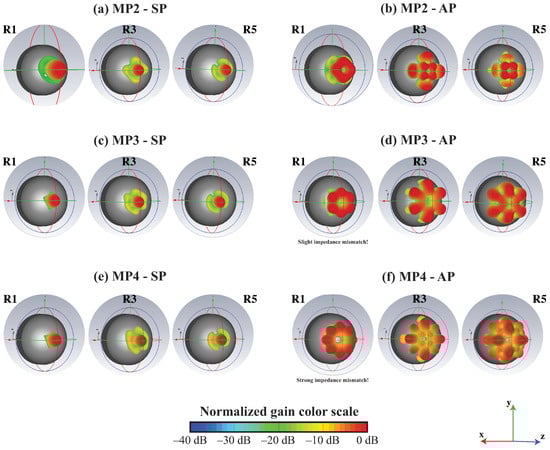
Figure 7.
Normalized far-field pattern simulations for the multipolar antennas coupled to a hyper-hemispherical lens. Associated realized gains are reported for each configuration. Diagrams are simulated for an emission at 100 GHz.
Table 4.
Key metrics at 100 GHz for different resonance designs (R1, R3, R5) of a standard dipole antenna, which utilizes a high-index substrate and a hyper-hemispherical lens, are evaluated using multipin excitation.
4. Discussion
We observed in Figure 4 that impedance matching at 100 GHz was not systematic for an antenna designed with crossed dipoles working at first resonance (R1), i.e., for a dipole length , but that it could be possible for some antenna designed for third-order (R3 for ) or fifth-order (R5 for ) resonances. Impedance matching is verified at 100 GHz for all resonances since the S parameter is below −10 dB for all antennas at this design frequency. As expected, multiple resonances appear as the resonance order N increases, and resonant frequencies are the odd multiples of the free spectral range, i.e., odd multiples of 100 GHz/N. Obviously, the antenna bandwidth reduces as the resonance order increases; this could be limiting for high-data-rate communication experiments. The bandwidth could be increased using multipolar bow-tie antennas but impedance matching becomes challenging as arms become closer if compared to a dipole antenna; therefore, only dipole antennas were considered here. Figure 4a shows the parameter of the MP2 antenna designed for different resonances and super-dipole polarity. Figure 4b shows the S parameter for the MP2 design but with alternate polarity excitation. In this configuration, impedance matching is not verified at first resonance but can be achieved for the R3 and R5 designs, thus justifying the need to simulate these antennas at higher resonance orders. Actually, for the super-dipole configuration (SP), impedance matching is verified at the targeted frequency of 100 GHz, regardless of the resonance order, for the MP2, MP3, and MP4 designs, as shown, respectively, in Figure 4a,c,e. Impedance matching seems impossible for the alternate polarity, as reported in Ref. [23]. We also observe that the S value at the design frequency of 100 GHz increases as the multipolar order increases; therefore, impedance matching becomes more difficult to achieve as the multipolar order increases, due to the fact that the antenna arms become closer as the multipolar order increases, thus increasing the coupling between antenna arms. For the alternate polarization (AP), we observe that impedance matching is barely verified for the MP3 antenna for resonance order R3, as shown in Figure 4d, and not verified for the MP4 geometry. This failure in impedance matching comes from the coupling between antenna arms that is even more deleterious for the alternate polarity than for the super dipole polarity, as destructive interferences can occur between neighboured arms with -shifted phases.
For the super-dipole configuration designed at first resonance, we observe the typical emission diagram of a standard dipole antenna (Figure 5). As the resonance order increases, the emission diagram is more diffractive and likely not adequate for typical applications. For the alternate-polarity excitation, we observe minimal radiation along the pointing direction of the antenna, likely due to destructive interference resulting from the alternate polarity. However, well-defined lobes surrounding the pointing direction are observed, which could be exploited in advanced applications requiring a structured field (such as multiple targets, inhomogeneous complex-shaped targets, granulometry, etc.), although such multi-lobe beams are usually less in demand. Regarding first-order resonance design, directivity remains similar (≈2.3 dBi), but a bandwidth of about 30 GHz was simulated for MP3-SP and MP4-SP antennas. This is more attractive than the 19-GHz bandwidth of the dipole antenna. As higher-order resonance designs are concerned, gain, directivity, and bandwidth are more attractive for MP designs (except for the MP4-SP antenna designed at the fifth-order resonance). In summary, impedance-matched MP antennas using vacuum as a background offer, in most cases, better performance than the dipole antenna in terms of bandwidth and directivity, thus reinforcing the interest in such antenna designs.
As shown in Figure 7 for antennas designed on a high-index substrate that includes a hyper-hemispherical lens, in comparison to antennas designed for the vacuum background, radiation points towards the z-direction, thanks to the lens. For super-dipole-like polarity, we do not observe the radiation diagram that is typical for a dipole antenna, but rather a quite directive beam with a full beamwidth at 3 dB between 17 and 20 in these simulations. As observed in Table 3, for the super-dipole polarity, gain ranges from 14.5 dBi to 16.1 dBi, bandwidths from 10 to 39 GHz, and directivities from 17.7 to 18.4 dBi, thus offering quite attractive performances with high gain/directivity and wide bandwidth, suitable for applications such as high-data-rate communications up to 20 Gbps or imaging systems. In regard to alternate polarity, one can observe that impedance matching was verified for the first-resonance antenna, but only for MP2 geometry; it could not be obtained using vacuum as the background. For higher resonance orders, impedance matching could also be achieved using a high-index substrate. However, similar to the far-field radiation patterns simulated with the vacuum as background, there is a node in the centre of the radiation diagram for all antennas designed with alternate polarity. This feature might be interesting for some specific applications but would require a particular detection scheme. Additionally, the resulting gain, bandwidth, and directivity are reduced in comparison to those with super-dipole polarity. In terms of polarization, we were able to verify that linear polarization is achieved for all impedance-matched configurations, with an axial ratio of more than 40 dB in the centre of each lobe. However, the orientation of the polarization is defined by the polarity geometry; therefore, for alternate-polarity configurations, each lobe presents its own orientation of the linearly polarized electric field, defined by the positions of neighboured pins couples. Similar to the case of antennas with vacuum as the background, one could compare the performance of MP antennas on a high-index hyper-hemispherical lens with that of dipole antennas realized on the same substrate. We observe in Table 4 that gain, bandwidth, and directivity are quite similar to the super-dipole polarity MP antennas. Therefore, these multipolar antennas mounted on high-index hyper-hemispherical lenses could be used for the coherent combination of multiple beat spots in the context of photomixing-based THz emission.
Finally, we should recall that the primary aim of this study is to possibly increase the emitted THz power through coherent beam combination on the photomixing antenna. Gain and directivity are quite similar for the standard dipole design and the MP designs in an SP configuration, but for the MP design, x beat spots are exploited, while a single one is used to excite a standard dipole antenna. Therefore, the MP antenna is driven by a photocurrent that is times stronger, so the resulting power should increase by a factor of , i.e., up to for the MP4 design.
5. Conclusions
We presented simulations of a multipolar antenna design for photomixing applications driven by a dual-frequency laser emitting on two Laguerre–Gauss transverse modes. We have shown that impedance mismatch is possible, but that elementary dipole antennas might need to be designed at higher resonance orders in some cases, specifically for alternate polarity. We confirmed that the polarity distribution of the elementary antenna arms’ excitation plays a significant role in the far-field distribution, and that attractive far-field patterns can be expected using a high-index hyper-hemispherical lens substrate, along with high realized gain and directivity. Optimum performances are obtained for antennas designed at the first resonance with a super-dipole-like polarity, using either MP2, MP3, or MP4 geometries. Concerning alternate polarity, impedance matching becomes more challenging, and the realized gain, bandwidth, and directivity are less attractive. More importantly, the far-field radiation pattern presents a node along the propagation axis, which might be prohibitive in standard systems. The polarity could be adjusted to switch from the intrinsic alternate polarity of the optical excitation to a more suitable super-dipole-like polarity. This adjustment can be achieved either by using specific diffractive optics while being mindful of limiting associated coupling losses towards the photomixer array, or by employing fan-in waveguides, as proposed in [14], where each incoming fibre might benefit from phase control to ensure a coherent combination of optical beat signals on the photomixer array with the desired polarity. In any case, this approach should be an alternative to existing solutions to increase the emitted THz power resulting from photomixing, at least for the specific dual-frequency optical excitation based on superimposed transverse modes. For the LG/LG couple excitation, an improvement factor of 64 could be expected for the THz power using MP4 geometry. If these results were confirmed experimentally, along with an acceptable way to control the polarity, this study would lead to the development of high-power lasers working on LG/LG mode couples, with a higher possible value of x, while ensuring frequency noise correlation between the modes, thus offering an attractive improvement factor of the THz output power. This work also opens up the path to functionalize the spatial structure of THz light for advanced applications (e.g., high paraxial spatial coherence, beam steering, multiplexing…).
Author Contributions
Conceptualization, S.B.; methodology, A.A.; validation, A.A., A.P., P.N., A.G. and S.B.; investigation, A.A.; data curation, A.A.; writing—original draft preparation, S.B.; writing—review and editing, S.B.; visualization, A.A. and S.B.; supervision, S.B.; project administration, S.B.; funding acquisition, S.B. All authors have read and agreed to the published version of the manuscript.
Funding
This research was funded by Agence Nationale de la Recherche, grant number ANR–19–CE24-0012 (SPATIOTERA); I-SITE MUSE (STAE): grant number AAP2021; Région Occitanie/Pyrénées-Méditerranée; European Regional Development Fund (HERMES platform).
Institutional Review Board Statement
Not applicable.
Informed Consent Statement
Not applicable.
Data Availability Statement
The data presented in this study are available on request from the corresponding authors. Due to the substantial volume of data, it is not publicly accessible.
Acknowledgments
The authors thank the C2N CNRS RENATECH network, including I. Sagnes, G. Beaudoin, and K. Pantzas, for processing semiconductor VeCSEL technology.
Conflicts of Interest
The authors declare no conflict of interest.
Abbreviations
The following abbreviations are used in this manuscript:
| AP | alternate polarity |
| CST | computer simulation technology |
| FiOR | fifth-order resonance |
| FOR | first-order resonance |
| LG | Laguerre–Gauss |
| MP | multipolar |
| MPA | multipolar antennas |
| SP | super-dipole polarity |
| TOR | third-order resonance |
| UTC | uni-traveling carrier photodiodes |
| VeCSEL | vertical external-cavity surface-emitting laser |
Appendix A
Appendix A.1
To confirm the validity of the simulations using the multipin port, we conducted a comparative study for a standard dipole antenna, excited either by a biaxial cable or a standard discrete port excitation proposed in CST. The dipole antenna consists of two perfect electric conductors, with a width of 40 m, spaced by 80 m, using vacuum as the background. Port impedance is fixed to 75 for both simulations to match with the standard dipole impedance; port impedance is ensured for the multipin excitation by choosing a pin diameter of 13.35 m. For the multipin excitation, the arm length is 685 m, while it is 660 m for the dipole excitation, for better impedance matching at 100 GHz. Figure A1a presents the resulting parameter as a function of frequency for both excitations, showing an impedance-matched antenna for both excitations at 100 GHz, without any significant difference due to the excitation type.
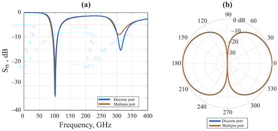
Figure A1.
Validation of multipin port excitation in comparison to standard port excitation; (a) S parameters for multipin or discrete port excitation of a standard dipole antenna designed at 100 GHz; (b) normalized far-field radiation patterns for both excitations.
Figure A1.
Validation of multipin port excitation in comparison to standard port excitation; (a) S parameters for multipin or discrete port excitation of a standard dipole antenna designed at 100 GHz; (b) normalized far-field radiation patterns for both excitations.
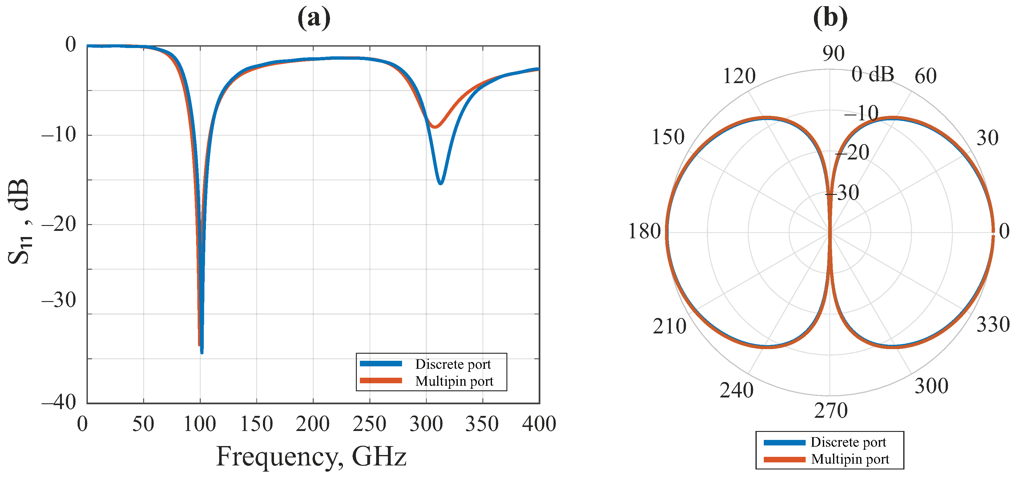
Figure A1b shows the far-field radiation pattern, where the typical pattern of a dipole antenna is obtained, as expected, being nearly identical for both excitations. Table A1 synthesizes the comparative study conducted for the two types of excitation, recalling the antenna design parameters used to optimize impedance matching at the designed frequency of 100 GHz, and reporting similar antenna performances in terms of realized gain and impedance-matching bandwidth (at −10 dB), thus validating this method based on multipin port excitation to simulate multipolar antennas.
Table A1.
Comparison between discrete port excitation and multipin port excitation for a dipole antenna.
Table A1.
Comparison between discrete port excitation and multipin port excitation for a dipole antenna.
| Dimensions | dis. port | mul. port | Antennas Metrics | dis. port | mul. port |
|---|---|---|---|---|---|
| Arm length (mm) | 0.66 | 0.685 | Realized Gain (dBi) | 2.2 | 2.2 |
| Gap (m) | 40 | 40 | Bandwidth (GHz) | 14.3 | 14.6 |
| Arm width (m) | 80 | 80 | Directivity (dBi) | 2.2 | 2.3 |
Appendix A.2
We compare the antenna with perfect materials (PEC for the antenna and Si for the lens) to the ideal antenna (gold for the antenna, Si for the lens, and GaAs for the photo-conductor). For this, we use the refractive index reported in the literature [30]. The simulated antenna is MP3 R1 AP and the refractive index of the materials used in these simulations are as follows: for GaAs and for Si. Regarding the gold, its properties are available in the database of CST Studio Suite, including specific parameters (permeability, electrical conductivity, etc.). Figure A2a presents the resulting S as a function of frequency for both real and ideal materials, showing similar results. For the lens, which has no anti-reflective coating, we can see slight oscillations likely linked to the air/Si interfaces. Figure A2 shows similar far-field radiation patterns with both real and ideal materials. The obtained results are also shown in Table A2, which reports similar findings in terms of bandwidth, realized gain, and directivity. In conclusion, using materials that closely resemble reality, we found very similar results, further confirming the accuracy of our simulations.
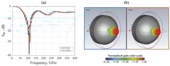
Figure A2.
Comparison between real-life materials; (a) S parameters of ideal and real materials; (b) far-field radiation patterns.
Figure A2.
Comparison between real-life materials; (a) S parameters of ideal and real materials; (b) far-field radiation patterns.
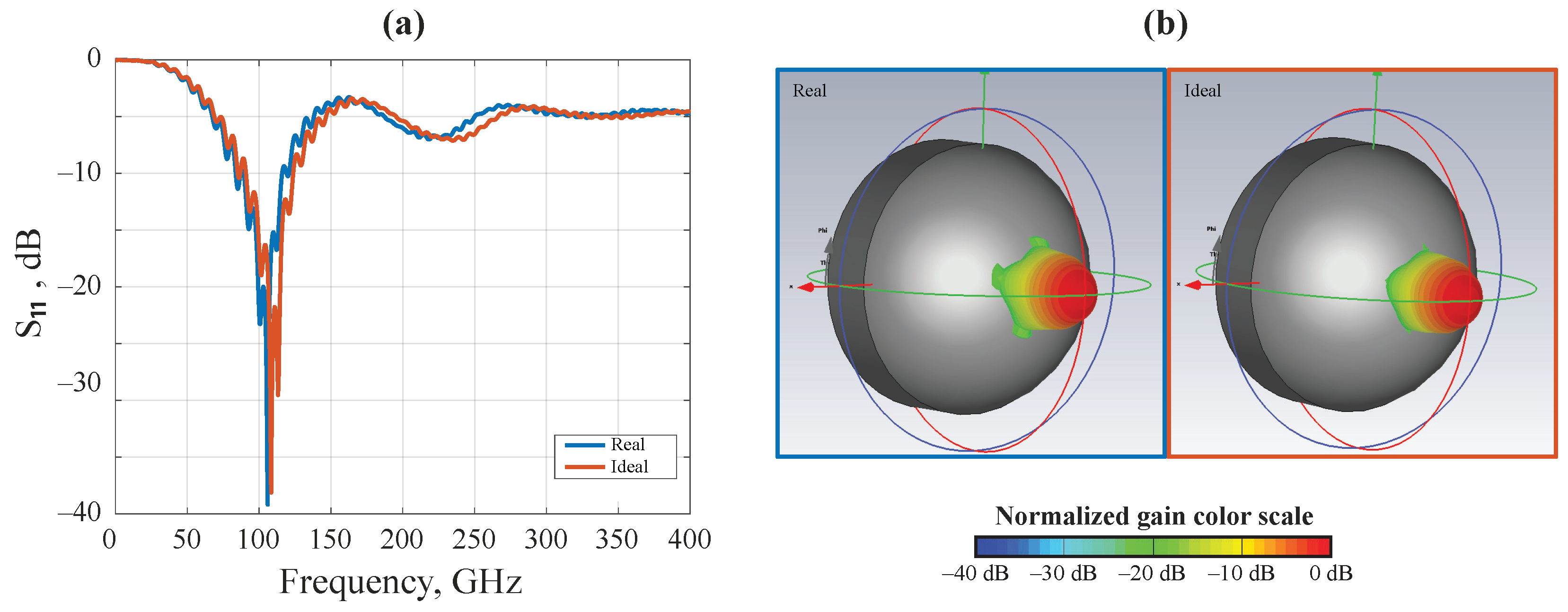
Table A2.
Comparison between real and ideal materials.
Table A2.
Comparison between real and ideal materials.
| Material | S (dB) | Bandwidth (GHz) | Realized Gain (dBi) | Directivity (dBi) |
|---|---|---|---|---|
| Ideal | −17 | 32.7 | 15.7 | 18.4 |
| Real | −22 | 36.4 | 15.8 | 18.4 |
Appendix A.3
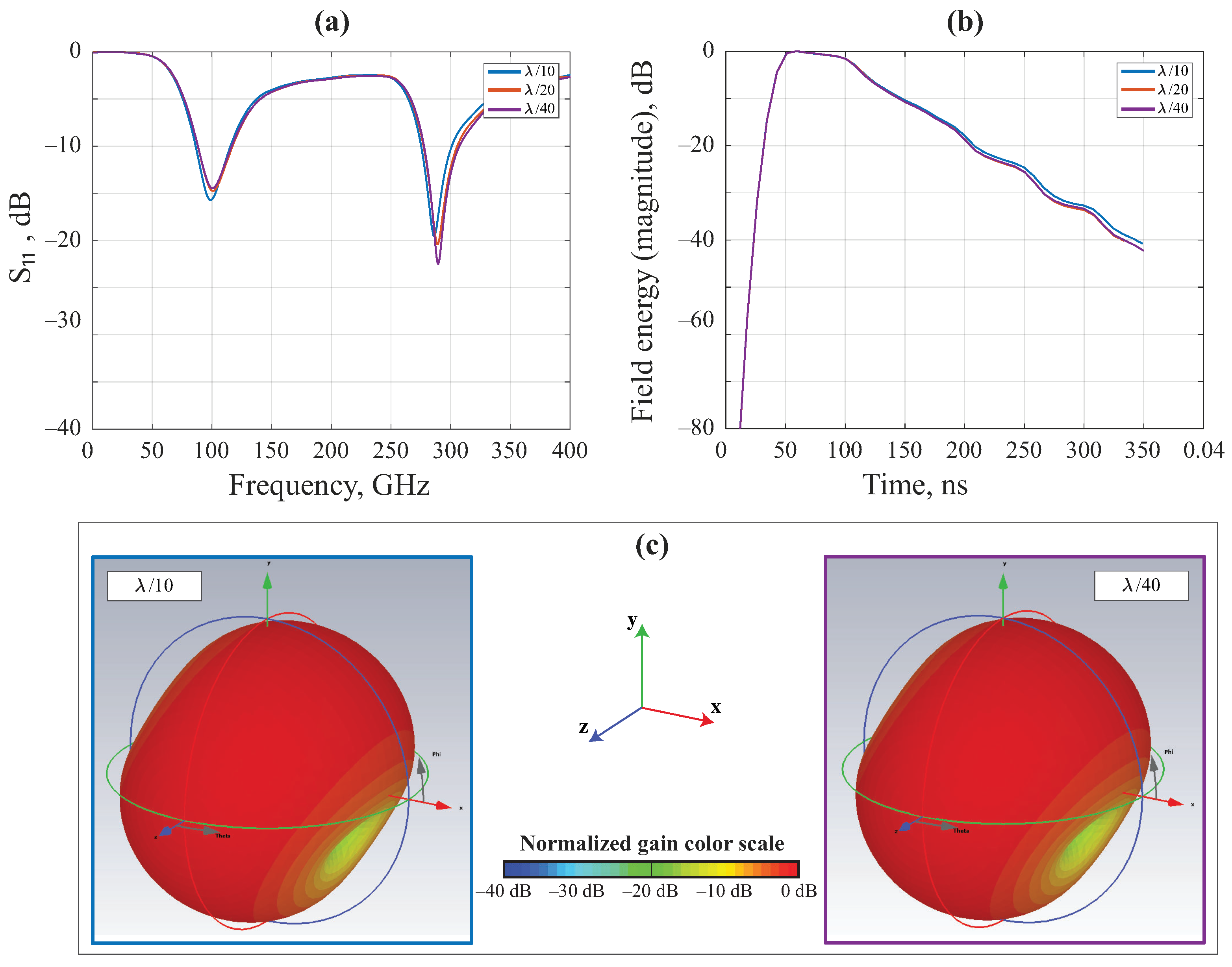
Here, we show that the chosen hexahedral mesh of /40 is sufficient for our simulations. In Figure A3a, we show the S parameter as a function of the frequency for /10, /20, and /40, which present similar results. Figure A3b shows the field energy as a function of time; again, we see similarities between all three different hexahedral mesh values. Figure A3c shows similar far-field radiation patterns for both /10 and /40. Finally, Table A3 shows the values of the realized gain and the number of meshes for the three hexahedral mesh values. The obtained simulation results converge, and the number of meshes at /40 is sufficient to obtain meaningful data.
Table A3.
Antenna performances and number of meshes.
Table A3.
Antenna performances and number of meshes.
| Hexahedral Mesh | Realized Gain (dBi) | Number of Meshes (Millions) |
|---|---|---|
| /10 | 1.58 | 0.552 |
| /20 | 1.56 | 3 |
| /40 | 1.55 | 21 |

Figure A3.
Validation of accuracy; (a) S parameter for different values; (b) field energies for different values; (c) far-field radiation patterns for /10 and /40.
Figure A3.
Validation of accuracy; (a) S parameter for different values; (b) field energies for different values; (c) far-field radiation patterns for /10 and /40.
References
- Song, H.J.; Lee, N. Terahertz Communications: Challenges in the Next Decade. IEEE Trans. Terahertz Sci. Technol. 2022, 12, 105–117. [Google Scholar] [CrossRef]
- Petrov, V.; Kurner, T.; Hosako, I. IEEE 802.15.3d: First Standardization Efforts for Sub-Terahertz Band Communications toward 6G. IEEE Commun. Mag. 2020, 58, 28–33. [Google Scholar] [CrossRef]
- Dang, S.; Amin, O.; Shihada, B.; Alouini, M.S. What should 6G be? Nat. Electron. 2020, 3, 20–29. [Google Scholar] [CrossRef]
- Polese, M.; Jornet, J.M.; Melodia, T.; Zorzi, M. Toward End-to-End, Full-Stack 6G Terahertz Networks. IEEE Commun. Mag. 2020, 58, 48–54. [Google Scholar] [CrossRef]
- Rappaport, T.S.; Xing, Y.; Kanhere, O.; Ju, S.; Madanayake, A.; Mandal, S.; Alkhateeb, A.; Trichopoulos, G.C. Wireless Communications and Applications Above 100 GHz: Opportunities and Challenges for 6G and Beyond. IEEE Access 2019, 7, 78729–78757. [Google Scholar] [CrossRef]
- Deumer, M.; Stiewe, O.; Nellen, S.; Kohlhaas, R.B.; Elschner, R.; Schubert, C.; Freund, R.; Schell, M. Purely photonic wireless link at 120 GHz carrier frequency enabled by heterodyne detection with a photoconductive antenna. In Proceedings of the Terahertz, RF, Millimeter, and Submillimeter-Wave Technology and Applications XVI, San Francisco, CA, USA, 28 January–3 February 2023; Sadwick, L.P., Yang, T., Eds.; International Society for Optics and Photonics—SPIE: Bellingham, WA, USA, 2023; Volume 12420, p. 1242005. [Google Scholar]
- Dhillon, S.; Vitiello, M.; Linfield, E.; Davies, A.; Hoffmann, M.C.; Booske, J.; Paoloni, C.; Gensch, M.; Weightman, P.; Williams, G.; et al. The 2017 terahertz science and technology roadmap. J. Phys. D Appl. Phys. 2017, 50, 043001. [Google Scholar] [CrossRef]
- Song, H.J.; Ajito, K.; Muramoto, Y.; Wakatsuki, A.; Nagatsuma, T.; Kukutsu, N. Uni-travelling-carrier photodiode module generating 300 GHz power greater than 1 mW. IEEE Microw. Wirel. Components Lett. 2012, 22, 363–365. [Google Scholar] [CrossRef]
- Lu, P.K.; Jarrahi, M. Plasmonics-enhanced Photoconductive Terahertz Devices. In Fundamentals of Terahertz Devices and Applications; John Wiley & Sons Ltd.: Hoboken, NJ, USA, 2021; pp. 187–219. [Google Scholar]
- Zhou, Y.; Sakano, G.; Yamanaka, Y.; Ito, H.; Ishibashi, T.; Kato, K. 600-GHz-wave beam steering by terahertz-wave combiner. In Proceedings of the 2018 Optical Fiber Communications Conference and Exposition (OFC), San Diego, CA, USA, 11–15 March 2018; pp. 1–3. [Google Scholar]
- Matsuo, Y.; Che, M.; Kanaya, H.; Kato, K. THz-wave power multiplication by parallel-connection UTC-PDs. In Proceedings of the 2020 Opto-Electronics and Communications Conference (OECC), Taipei, Taiwan, 4–8 October 2020; pp. 1–4. [Google Scholar]
- Che, M.; Kondo, K.; Ibrahim, A.A.; Kato, K. Optical Group-delay Filters for 300-GHz-wave Beam Steering. In Proceedings of the Optoelectronics and Communications Conference, Hong Kong, China, 3–7 July 2021; pp. 1–3. [Google Scholar]
- Che, M.; Matsuo, Y.; Kanaya, H.; Ito, H.; Ishibashi, T.; Kato, K. Optoelectronic THz-wave beam steering by arrayed photomixers with integrated antennas. IEEE Photonics Technol. Lett. 2020, 32, 979–982. [Google Scholar] [CrossRef]
- Sawadogo, B.A.; Bandyopadhyay, A.; Zegaoui, M.; Zaknoune, M.; Szriftgiser, P.; Baudelle, K.; Bouet, M.; Bouwmans, G.; Gaillot, D.P.; Andresen, E.; et al. 100 Gbit/s THz Data Transmission and Beyond using Multicore Fiber Combined with UTC Photodiode Array. In Proceedings of the 2022 Optical Fiber Communications Conference and Exhibition (OFC), San Diego, CA, USA, 6–10 March 2022; pp. 1–3. [Google Scholar]
- García-Muñoz, E.; Abdalmalak, K.; Santamaría, G.; Rivera-Lavado, A.; Segovia-Vargas, D.; Castillo-Araníbar, P.; Van Dijk, F.; Nagatsuma, T.; Brown, E.; Guzman, R.; et al. Photonic-based integrated sources and antenna arrays for broadband wireless links in terahertz communications. Semicond. Sci. Technol. 2019, 34, 054001. [Google Scholar] [CrossRef]
- Che, M.; Kondo, K.; Kanaya, H.; Kato, K. Arrayed Photomixers for THz Beam-Combining and Beam-Steering. J. Light. Technol. 2022, 40, 6657–6665. [Google Scholar] [CrossRef]
- Offermans, P.; Zhang, L.; Kasture, S.; Jansen, R.; de Heyn, P.; Song, J.; Janssen, S.; Balakrishnan, S.; Soussan, P.; Van Campenhout, J.; et al. Towards THz beam steering with integrated phased photomixer arrays. In Proceedings of the Terahertz, RF, Millimeter, and Submillimeter-Wave Technology and Applications XIV, Online, 6–12 March 2021; Volume 11685, pp. 181–188. [Google Scholar]
- Döhler, G.H.; Garcia-Muñoz, L.E.; Preu, S.; Malzer, S.; Bauerschmidt, S.; Montero-de Paz, J.; Ugarte-Munoz, E.; Rivera-Lavado, A.; Gonzalez-Posadas, V.; Segovia-Vargas, D. From arrays of THz antennas to large-area emitters. IEEE Trans. Terahertz Sci. Technol. 2013, 3, 532–544. [Google Scholar] [CrossRef]
- Preu, S.; Malzer, S.; Döhler, G.; Zhang, J.; Lu, Z.; Wang, L. Highly collimated and directional continous-wave terahertz emission by photomixing in semiconductor device arrays. In Proceedings of the Millimeter-Wave and Terahertz Photonics, Strasbourg, France, 3–7 April 2006; Volume 6194, pp. 111–119. [Google Scholar]
- Paquet, R.; Blin, S.; Myara, M.; Le Gratiet, L.; Sellahi, M.; Chomet, B.; Beaudoin, G.; Sagnes, I.; Garnache, A. Coherent continuous-wave dual-frequency high-Q external-cavity semiconductor laser for GHz–THz applications. Opt. Lett. 2016, 41, 3751–3754. [Google Scholar] [CrossRef]
- Blin, S.; Paquet, R.; Myara, M.; Chomet, B.; Le Gratiet, L.; Sellahi, M.; Beaudoin, G.; Sagnes, I.; Ducournau, G.; Latzel, P.; et al. Coherent and tunable thz emission driven by an integrated III–V semiconductor laser. IEEE J. Sel. Top. Quantum Electron. 2017, 23, 1–11. [Google Scholar] [CrossRef]
- Abbes, A.; Lu, P.K.; Nouvel, P.; Pénarier, A.; Varani, L.; Beaudoin, G.; Sagnes, I.; Garnache, A.; Jarrahi, M.; Blin, S. 280 GHz radiation source driven by a 1064 nm continuous-wave dual-frequency vertical external cavity semiconductor laser. In Proceedings of the 2021 46th International Conference on Infrared, Millimeter and Terahertz Waves (IRMMW-THz), Chengdu, China, 29 August–3 September 2021; pp. 1–2. [Google Scholar]
- Meyer, P.; Prinsloo, D.S. Generalized multimode scattering parameter and antenna far-field conversions. IEEE Trans. Antennas Propag. 2015, 63, 4818–4826. [Google Scholar] [CrossRef]
- Seeds, A.J.; Fice, M.J.; Balakier, K.; Natrella, M.; Mitrofanov, O.; Lamponi, M.; Chtioui, M.; van Dijk, F.; Pepper, M.; Aeppli, G.; et al. Coherent terahertz photonics. Opt. Express 2013, 21, 22988–23000. [Google Scholar] [CrossRef] [PubMed]
- Garufo, A.; Sberna, P.M.; Carluccio, G.; Freeman, J.R.; Bacon, D.R.; Li, L.; Bueno, J.; Baselmans, J.J.; Linfield, E.H.; Davies, A.G.; et al. A connected array of coherent photoconductive pulsed sources to generate mW average power in the submillimeter wavelength band. IEEE Trans. Terahertz Sci. Technol. 2019, 9, 221–236. [Google Scholar] [CrossRef]
- Natrella, M.; Liu, C.P.; Graham, C.; van Dijk, F.; Liu, H.; Renaud, C.C.; Seeds, A.J. Modelling and measurement of the absolute level of power radiated by antenna integrated THz UTC photodiodes. Opt. Express 2016, 24, 11793–11807. [Google Scholar] [CrossRef] [PubMed]
- Renaud, C.C.; Natrella, M.; Graham, C.; Seddon, J.; Van Dijk, F.; Seeds, A.J. Antenna integrated THz uni-traveling carrier photodiodes. IEEE J. Sel. Top. Quantum Electron. 2017, 24, 1–11. [Google Scholar] [CrossRef]
- Garufo, A.; Carluccio, G.; Freeman, J.R.; Bacon, D.R.; Llombart, N.; Linfield, E.H.; Davies, A.G.; Neto, A. Norton equivalent circuit for pulsed photoconductive antennas—Part II: Experimental validation. IEEE Trans. Antennas Propag. 2018, 66, 1646–1659. [Google Scholar] [CrossRef]
- Garufo, A.; Carluccio, G.; Llombart, N.; Neto, A. Norton equivalent circuit for pulsed photoconductive antennas—Part I: Theoretical model. IEEE Trans. Antennas Propag. 2018, 66, 1635–1645. [Google Scholar] [CrossRef]
- Klier, J.; Torosyan, G.; Schreiner, N.S.; Molter, D.; Ellrich, F.; Zouaghi, W.; Peytavit, E.; Lampin, J.F.; Beigang, R.; Jonuscheit, J.; et al. Influence of substrate material on radiation characteristics of THz photoconductive emitters. Int. J. Antennas Propag. 2015, 2015, 1–7. [Google Scholar] [CrossRef]

Disclaimer/Publisher’s Note: The statements, opinions and data contained in all publications are solely those of the individual author(s) and contributor(s) and not of MDPI and/or the editor(s). MDPI and/or the editor(s) disclaim responsibility for any injury to people or property resulting from any ideas, methods, instructions or products referred to in the content. |
© 2023 by the authors. Licensee MDPI, Basel, Switzerland. This article is an open access article distributed under the terms and conditions of the Creative Commons Attribution (CC BY) license (https://creativecommons.org/licenses/by/4.0/).