Abstract
In response to the growing need for enhanced space environment detection in ultra-low Earth orbits, this study introduces a pioneering design for a reconfigurable single-board satellite. Beyond the conventional attributes of compactness and a lightweight design, the single-board satellite also has unique features that are reconfigurable for the space detection mission it undertakes, as well as autonomous Earth communication capabilities that are not available in other very small satellites. Such advancements address the limitations of traditional very small satellites such as CubeSats and ChipSats. This paper delves deeply into the satellite’s design feasibility, including its functional requirements, power equilibrium, and communication links. Supplementing our design, a proof-of-concept prototype was crafted, and rigorous laboratory tests were performed to corroborate its key specifications and functionalities.
1. Introduction
With the increasing prevalence of space exploration activities, there is a growing emphasis on space environment investigations in ultra-low Earth orbits. For instance, variations in atmospheric density can have a significant impact on satellites operating at these altitudes, and fluctuations in the electron density of the ionosphere can severely affect space-to-ground communications [1,2].
In response to the escalating demands for ultra-low Earth orbit space environment investigations, novel exploration technologies are gradually gaining traction. Balloon satellites have emerged as a means to integrate microsatellites within balloons for in situ measurements of atmospheric density in ultra-low orbits [3,4,5]. Low-cost ionospheric occultation detection employing microsatellites or even very small (sub-kilogram) satellites is also being progressively applied in this context [6]. These innovative exploration techniques impose fresh requirements on microsatellites. For instance, in atmospheric density measurements, reducing the mass and volume of satellites is imperative to enhance the mass-to-surface area ratio of balloon satellites, thereby improving measurement precision [7]. Similarly, in ultra-low Earth orbit ionospheric occultation detection, further reductions in satellite mass and volume are essential to lower costs and increase the number of exploratory missions [8,9].
In addition, considering that the available resources of very small satellites are limited, they must be able to flexibly switch modes according to ground needs at different altitudes and scenarios, which also places requirements on satellite–ground communication capabilities. In terms of satellite communications, in particular, satellite–ground integrated networks have been extensively studied and have made significant progress, providing greater possibilities for the exploration of lightweight, independent ground-communication microsatellites [10,11,12,13]. In essence, ultra-low orbit investigations necessitate an extremely lightweight, independently Earth-communicating, and adaptable satellite.
Mature very small satellite designs can be broadly categorized into CubeSats and PCB satellites [14,15]. In the aerospace industry, there is an established set of design norms and standards specifically for CubeSats [16]. They have independent satellite–ground communication capabilities and can perform direct in-orbit mission reconstruction. Additionally, CubeSats have successfully launched and completed numerous space missions [17]. However, their mass usually exceeds 1 kg, and their volume is at least 1 U, which cannot fully meet the requirements of ultra-low orbit space exploration missions. Notably, there is huge optimization potential in terms of mass and volume.
Pico- and femto-satellites, which are notably smaller in both mass and volume, are predominantly utilized for investigating low-orbit space. Given their severely limited onboard resources, these satellites typically depend on their parent satellites for communication with Earth. The University of Surrey in the UK has introduced the concepts of on-chip satellites (SpaceChip) and printed circuit board satellites (PCBSat). They have engineered various PCBSats using commercial off-the-shelf (COTS) electronic components to assess their capability in conducting space missions [18,19]. Notably, Ryerson University’s RyeFemSat in Canada and Polytechnic University of Barcelona’s WikiSat in Spain have successively demonstrated the viability of constructing low-cost, lightweight, and miniaturized onboard satellites [20,21].
Current very small satellites do not adequately cater to the unique requirements of ultra-low orbit space environment studies. Therefore, this paper focuses on introducing and optimizing a new type of very small satellite, uniquely designed for the evolving demands of space exploration: an online-reconfigurable single-board satellite. Our primary investigation revolves around its technical feasibility, examining critical aspects such as power, communication, mass, volume, and other essential parameters. The prototype we developed is compact and lightweight, demonstrating enhanced performance in key aspects such as energy provisioning, consumption, and data transmission capacities. This novel design unlocks fresh technological avenues for conducting research in the ultra-low Earth orbit space environment.
2. Space Environment Detection Needs Analysis
2.1. Analysis of Balloon Satellite Detection Needs
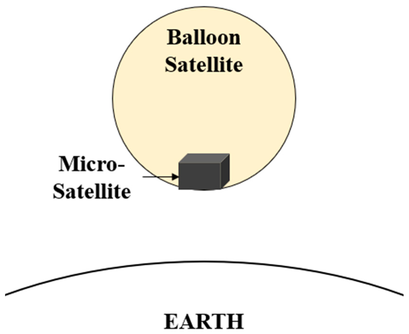
As shown in Figure 1, utilizing balloon satellites for in situ atmospheric density measurements necessitates the deployment of GNSS (Global Navigation Satellite System) modules to record orbital parameters, such as position and velocity, while the balloon satellite autonomously traverses through the atmosphere’s resistance [22]. These recorded data are subsequently transmitted to ground stations, allowing for the derivation of atmospheric density information via force analysis. To enhance the mass-to-surface area ratio and, consequently, measurement accuracy, the composition of very small satellites within a balloon satellite must be simplified as much as possible.

Figure 1.
Schematic of the balloon satellite detection principle.
Upon analysis, it becomes evident that the internal very small satellites within a balloon satellite must, at a minimum, incorporate the following components:
- An energy unit, including solar panels, to provide power to all units;
- A GNSS unit for recording position and velocity;
- A communication unit for ground-based data transfer;
- A controller unit for mode control and GNSS data integration.
Furthermore, the operational principles of balloon satellites dictate that they do not require attitude control, propulsion, or similar functionalities. Unlike conventional CubeSats, the system architecture omits the need for units related to attitude control and propulsion. Simultaneously, to further reduce mass and volume, structural frameworks and other redundant backup units are unnecessary. However, this absence of fixed orientation presents challenges in terms of traditional solutions, such as sun-facing solar panels, directional GNSS antennas, and stable Earth communication strategies. Consequently, this necessitates innovative solutions to meet the omnidirectional requirements for power and communication.
2.2. Analysis of Ionospheric Occultation Detection Needs
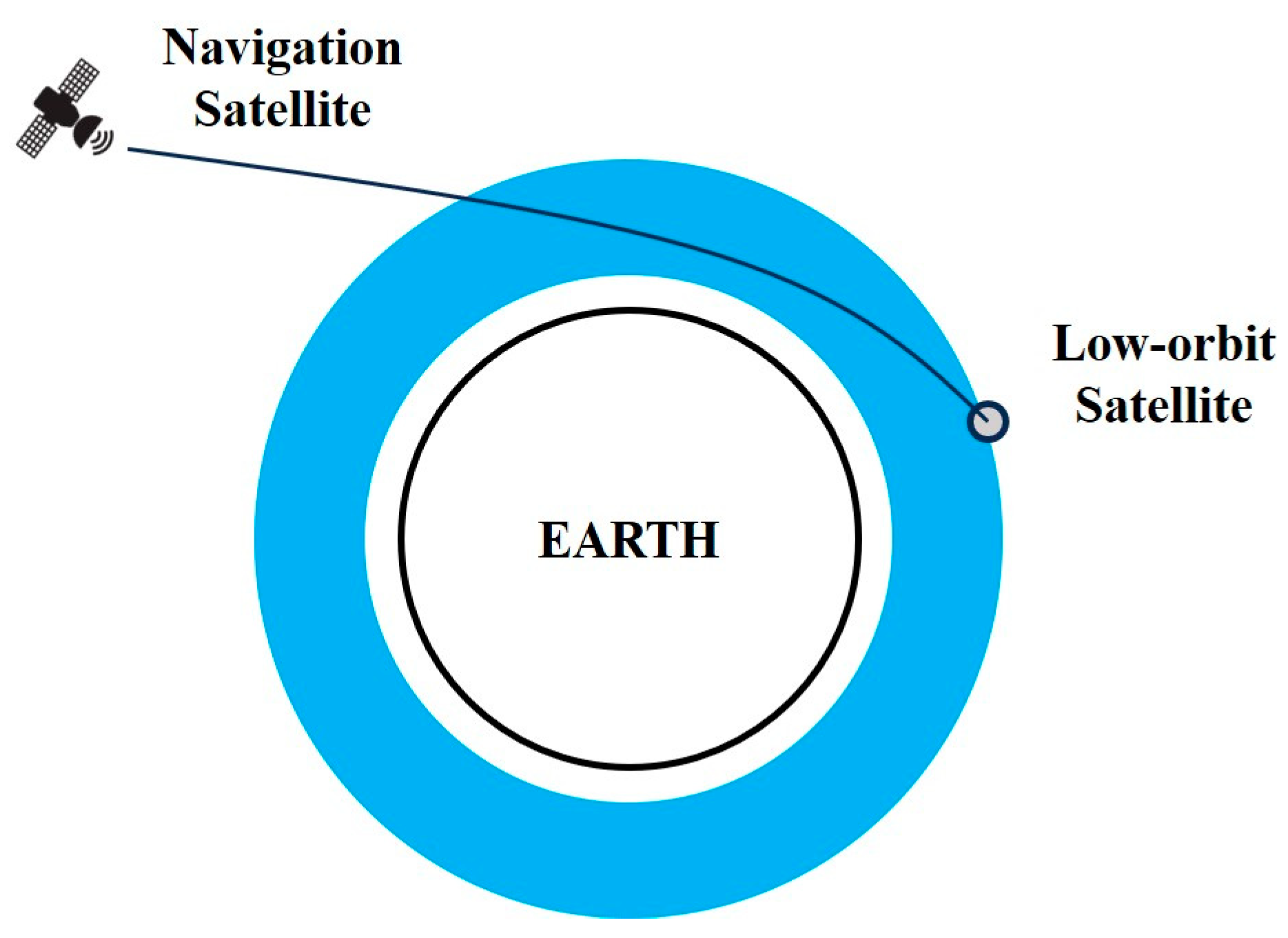
As illustrated in Figure 2, cost-effective ionospheric occultation detection requires the use of GNSS units to record pseudo-range and phase data, which are subsequently transmitted to the ground for ionospheric electron density inversion [23,24].

Figure 2.
Schematic of the low-cost ionospheric occultation detection principle.
In this detection mode, except for the GNSS unit receiving data, which requires the addition of pseudo-range and phase information of the navigation satellite, the rest is similar to atmospheric density detection:
- An energy unit, including solar panels, to provide power to all units;
- A GNSS unit for recording pseudo-range and phase data;
- A communication unit for ground-based data transfer;
- A controller unit for mode control and GNSS data integration.
Similar to atmospheric density measurements in balloon satellite missions, in the absence of attitude control and propulsion modules, solar panels, GNSS antennas, and ground antennas are expected to provide nearly omnidirectional coverage. Consequently, a design can be implemented for very small satellites to simultaneously accommodate the requirements of both of these scenarios.
However, unlike atmospheric density measurements conducted in balloon satellite missions, ionospheric occultation detection occurs at higher orbital altitudes and does not rely on external balloons. Instead, it necessitates the collection of pseudo-range and phase data from multiple candidate GNSS satellites. The data structure is more intricate, and the sampling rate varies. Considering the extremely limited onboard energy resources, the deployment of balloon satellites and low-cost ionospheric occultation detection is time-shared.
2.3. Summary
In response to the aforementioned two detection scenarios, there is a need for a very small satellite capable of operating within a range of orbital altitudes, gradually descending from 500 to 100 km. This very small satellite must possess the flexibility to switch between operational modes as required to conduct both occultation and in situ measurements.
3. Design of a Single-Board Satellite
Upon analysis of the detection requirements, it is evident that very small satellites, while ensuring the fulfillment of their fundamental functions, should prioritize compactness and lightness. Consequently, the necessity of the commonly used basic units for very small satellites is summarized in Table 1. Due to limitations of volume and power consumption, it is difficult for single-board satellites to adopt active thermal control system. In the aforementioned applications based on balloon satellites, attitude control systems and frame structures have also become unnecessary.

Table 1.
Necessity analysis of functional units.
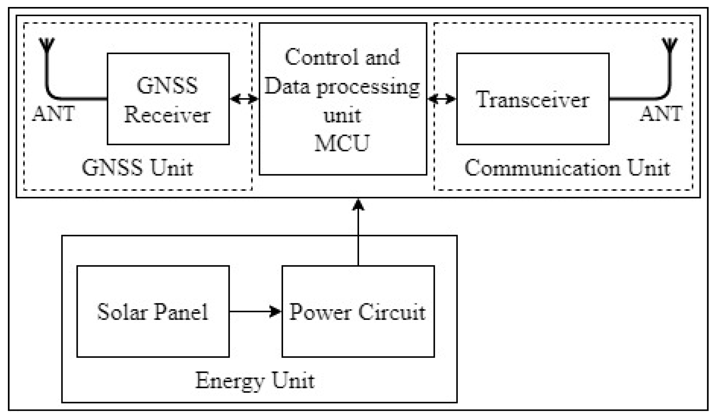
Differing from traditional very small satellites, the system configuration of the very small satellite proposed in this paper, in alignment with the detection needs, is depicted in Figure 3. It exclusively comprises an energy unit, GNSS unit, communication unit, and control and data processing unit. The control and data processing unit receives and stores data from the GNSS unit, while the communication unit transmits these data to ground stations during passes. The control and data processing unit conducts software reconfiguration based on the reconstruction information received from the ground station, facilitating the execution of various detection tasks. The power unit supplies energy to the aforementioned three units.
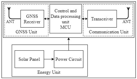
Figure 3.
Composition of a single-board satellite.
Taking into account the overall detection scenarios, the analysis of the different operational states required for this very small satellite is as follows:
- Detection task state: In the specified detection mode, it performs atmospheric density measurements or occultation detection of the corresponding space environment.
- Data transmission state: During the satellite-to-ground communication windows, it is responsible for communication with ground stations, including data uplink and downlink. Data uplink refers to the process whereby ground stations send reconfiguration code data and telecommand instructions to the single-board satellite for storage. Data downlink involves transmitting onboard detection data and telemetry data to ground stations via the transceiver.
- Reconfiguration state: Primarily responsible for tasks involving software function changes and program execution address transitions carried out by the onboard microcontroller. This state facilitates updates to the onboard detection mode.
- Standby state: Entered when energy is insufficient. During this state, the satellite solely charges to provide power for subsequent detection tasks. Since lithium batteries are used to store energy, the specific switching of the standby state is determined based on the voltage.
The relationships between these operational states are depicted in Figure 4.
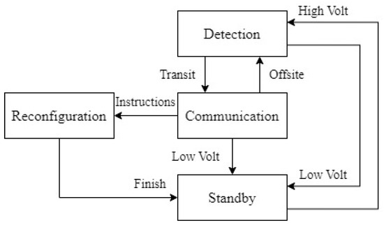
Figure 4.
Work mode and switching.
To conserve energy as much as possible, the status of each unit in the abovementioned operational states was designed as shown in Table 2, with a checkmark indicating normal operation during that state.
Table 2.
State design of the units.
The aforementioned units were designed in the form of a single-board satellite, with each unit referring to CubeSats or commercial industrial modules. The special requirements mentioned in the Necessity Analysis Table can be addressed as follows:
- Design solar panels with front and backside-mounted patches to achieve near-omnidirectional coverage;
- Arrange the GNSS antennas in two sets of back-to-back antennas to attain near-omnidirectional coverage;
- Data transmission and communication antennas employ mature UV band omnidirectional antennas to achieve near-omnidirectional coverage;
- Implement a simplified reconfiguration using an ARM-based microcontroller (MCU) without the combination of traditional FPGA and SoC methods, offering low power consumption and miniaturization.
For such a simplified single-board satellite, the two primary challenges encountered are the communication link and power supply. Therefore, further analysis of the feasibility of the communication link and power supply is required.
4. Feasibility Analysis
4.1. Communication Link Analysis
The satellite discussed in this paper operates within the UV frequency band. This frequency band is mature as a technology, simple to implement, energy-efficient, and easily facilitates omnidirectional transmission and reception. It is suitable for low-orbit satellites that aim to simplify attitude perception and control. Based on the theory of radio wave propagation, the margin calculation formula for the space-to-ground link is provided [25,26].
Within this formula, logarithmic calculations are represented by parentheses. Specifically:
- denotes the space-to-ground communication link margin, which indicates link reliability. In real-world space-to-ground communication links, a value of 3–6 dB or higher is appropriate;
- EIRP stands for effective isotropic radiated power and represents the transmission power capability of the transmitter. It is related to the transmission of power , antenna gain , and feeder loss ;
- represents free space loss, a reduction in energy caused by the spherical spread of electromagnetic waves. It is primarily determined by transmission distance (in meters) and frequency (in Hz) and constitutes the most significant loss in the link;
- is the quality factor at the receiving end, referring to the gain-to-system noise ratio. It characterizes the system’s receiving capability. Here, is the receiving end’s antenna gain, is the receiving end’s feeder loss, and T is the equivalent noise temperature of the receiving antenna;
- encompasses other combined losses during propagation, including atmospheric loss, antenna polarization loss, and ionospheric loss. stands for code rate, represents Boltzmann’s constant, valued at −228.6 dB/Hz·K, and signifies the signal-to-noise ratio per code element, which can be found in standard tables [27].
4.1.1. Downlink Margin Analysis
Based on the aforementioned theory and considering the parameters of commercially available industrial modules and existing ground-receiving equipment, the downlink margin was analyzed as follows:
Assuming the transmitter power is 500 mW (−3 dBW), the onboard omnidirectional antenna gain is −3.0 dBi, and the feeder loss is −0.5 dB, the effective isotropic radiated power, according to Formula (2), is −9.0 dBW. Assuming a downlink frequency of 433 MHz, a single-board satellite orbital altitude of 500 km, and a minimum elevation angle to the ground station of 20°, the free space loss, as per Formula (3), is −146.7 dB. Assuming the ground station’s receiving antenna gain is 14 dBi, with an equivalent noise temperature of 300 K and a receiving feeder loss of −0.5 dB, the quality factor at the receiving end, based on Formula (4), is −8.8 dB. Drawing from empirical values, the atmospheric loss is −1.0 dB, antenna polarization loss is −3.0 dB, ionospheric loss is −0.8 dB, and antenna pointing loss −1.0 dB, resulting in a total loss of −5.8 dB. Using BPSK modulation and given specific bit error rate requirements, which is 10−5, a table lookup yields a value of 10.5 dB. According to Formula (1), the satellite communication downlink margin is established.
Thus, the downlink meets the margin requirement of more than 6 dB, demonstrating strong interference resistance. The summarized calculation results are presented in Table 3.
Table 3.
Uplink and downlink budget.
4.1.2. Uplink Margin Analysis
Similarly, the margin analysis for the space-to-ground communication uplink was as follows:
Assuming the ground station transmission power is 30 W (15 dBW) and the ground transmission antenna gain is 12.0 dBi, drawing from empirical values, the feeder loss is −2.0 dB, leading to an effective isotropic radiated power of 25 dBW. With a downlink frequency of 170 MHz, the free space loss is −138.6 dB. Assuming the onboard omnidirectional antenna gain is −3.0 dBi, an equivalent satellite noise temperature of 1000 K, and a feeder loss of −0.5 dB, the quality factor at the receiving end, according to Formula (4), is −33.5 dB. The GFSK modulation method was selected for the uplink, and the receiver sensitivity is governed by:
In the equation, with an equivalent satellite noise temperature of 1000 K, the noise coefficient (NF) is 6.5 dB. When the code rate is set at 4.8 kbps, a table lookup yields a value of 13 dB. Based on Formula (1), the satellite communication uplink margin M is calculated as:
Hence, the uplink possesses a substantial margin, ensuring relatively reliable communication. A summary of the calculation results can be found in Table 3.
4.1.3. Data Volume Analysis
Considering the most basic data requirements for probing:
- Balloon Satellite Atmospheric Density Data Volume Analysis
Data content includes UTC, positioning status, ECEF (Earth-Centered, Earth-Fixed) position and velocity. The data size is 23 bytes with a sampling rate of 0.25 Hz. Additional information size, including the frame header, frame tail, and parity bits, amounts to 7 bytes. Thus, in the balloon satellite atmospheric density probing mode, the data volume is 634.5 KB per day.
- 2.
- Ionospheric Occultation Data Volume Analysis
Probing data consist of UTC, positioning status, ECEF position, and velocity, as well as pseudo-range, phase, and signal-to-noise ratio information for five optional satellites. The data size is 68 bytes with a sampling rate of 0.1 Hz. The additional information size remains at 7 bytes. Consequently, in the ionospheric occultation probing mode, the data volume is 634.5 KB per day.
- 3.
- Data Transmission Capability Analysis
From the link budget results, the ground station zenith angle coverage reaches 70°. It is inferred that the data transmission state during the effective space-to-ground communication window lasts up to 5 min.
Downlink: Typically, the satellite can complete three continuous orbits daily and establish communication with the ground station. With a downlink rate of 9600 bps, the daily downlink data volume peaks at 1080 KB, covering the aforementioned atmospheric density and ionospheric occultation data volume needs.
Uplink: Analogously, with an uplink rate of 4800 bps, the daily transit uplink data volume maximizes at 540 KB. The code volumes needed for online reconstruction are substantial. However, considering the low frequency of the data upload requirements, possibly only 1–2 times throughout the satellite’s lifespan, a multi-transmission approach is adopted for the upload of the reconstruction codes to address the data upload issue.
From the analyses, it is evident that using the mature UV frequency communication solution, including commercial UV transmitters and receivers, omnidirectional antennas, and ground stations, can meet the paper’s data downlink, uplink margin, and volume requirements.
4.2. Energy Consumption Analysis
To ensure that the power supply meets the stringent requirements of single-board satellite probing tasks and ground communication, this section accounts for energy consumption.
Based on Table 2 and the power consumption of the currently available commercial modules, an estimation of the power consumption for the single-board satellite is presented in Table 4. It is noted that the power consumption during data transmission and probing task states is relatively high. Furthermore, according to the conditions for switching between operational states, both the data transmission and probing task states serve as the primary operational states, whereas the reconstruction and standby states operate under specific conditions. Therefore, the data transmission and probing task states were taken as the typical operational states for power consumption analysis.
Table 4.
Power estimate of each work mode.
From the scenario analysis, the single-board satellite operates in a circular LEO orbit with altitudes ranging from 100 to 500 km, with an orbital period T of approximately 95 min. During the transit orbit, apart from 5 min allocated for ground communication, the satellite spends the remaining 90 min in the probing task state. The energy consumption estimate for a single orbit can be found in Table 5.
Table 5.
Single-track periodic energy consumption estimate.
Drawing from experience, a single GaAs solar cell with dimensions of 40 × 80 mm has a designed power output of 1.175 W. The direct sunlight duration within a single orbit is determined based on the duration of the earth’s shadow, which lasts for 36 min at an altitude of 500 km, as illustrated in Figure 5 [28]. This yields an effective sunlight exposure of 59 min.
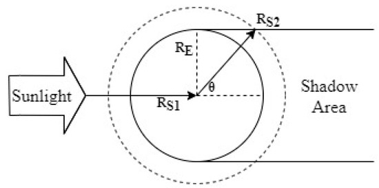
Figure 5.
Cylindrical shadow model.
Since there is no need for attitude control, the satellite, when in orbit, exhibits a random rotational state. The angle between sunlight and the solar cell’s normal varies randomly between 0 and 90°. Based on the solar cell correction model from reference [29], the average current reduction due to the angle of incidence is approximately 42.5%. With the power circuit’s charging efficiency being 80%, a single solar cell can provide power of 0.400 W. Therefore, at least six solar cells are required, offering an average power of 2.397 W and energy of 2.36 Wh per orbit, satisfying the entire satellite’s power consumption needs as analyzed in Table 6.
Table 6.
Parameters of the single-board satellite prototype.
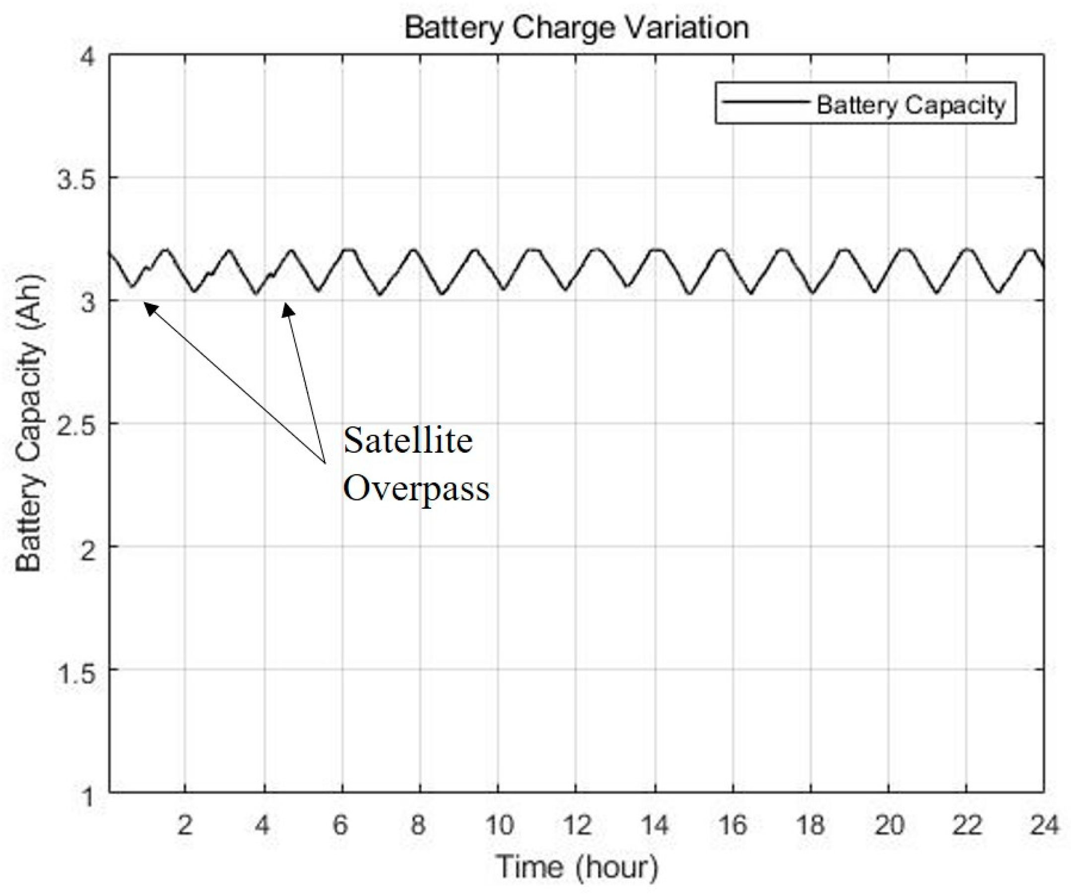
Further, a simulation analysis was conducted on the energy supply for the single-board satellite, considering six solar panels charging one 18650 lithium battery with a capacity of 3200 mAh. Assuming ground communication is established during three orbits within 24 h, the simulation results for the battery capacity variations are depicted in Figure 6. Over a 24-h cycle, the battery capacity remained above 90%.

Figure 6.
Energy simulation.
In conclusion, by employing six solar panels and one 18650 battery to power the control and data processing unit, GNSS unit, and data communication unit, an energy balance can be achieved when the entire satellite is in a random tumbling state.
5. Software-Based Approach for Online Reconfiguration
To facilitate the reconfiguration of onboard software and probing tasks for single-board satellites, as well as to cater to the potential expansion of future tasks, the incorporation of an online reconstruction feature on single-board satellites becomes imperative.
Traditional CubeSats with FPGA-based online reconfiguration can achieve dynamic restructuring of specified regions. However, their characteristic of multi-chip collaboration is not conducive to the lightweight design desired for single-board satellites. Aiming to ensure flexibility while pursuing miniaturization and low power consumption, this study opted for a software-based approach to online reconfiguration that leverages the booting characteristics of the ARM core. This method aptly balances advantages such as low cost, reduced power consumption, and compact design.
During the reconfiguration process, the data communication unit of the single-board satellite receives the onboard software reconstruction command and reconstruction code data transmitted from the ground station. These are then read and verified by the microcontroller. Once code transmission is complete, the code is sequentially written to the satellite’s external FLASH. After transmission of the reconfiguration data concludes, the microcontroller undergoes a software reset, entering the reconfiguration state. Using in-application programming (IAP), the reconfiguration code is transferred from the external FLASH to the corresponding address of the microcontroller’s onboard FLASH. Upon completion, another software reset is initiated. The bootloader then facilitates a transition to and execution of the reconfigured application, enabling task switching for objectives such as atmospheric density probing and ionospheric occultation detection [30]. The process is illustrated in Figure 7.
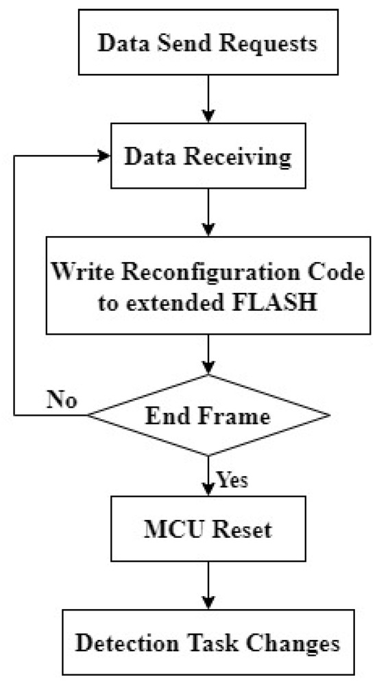
Figure 7.
Flowchart of the reconfiguration process.
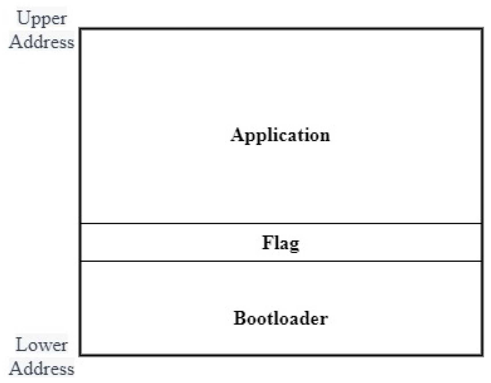
The onboard software primarily comprises a program that facilitates reconfiguration, i.e., the bootloader and the satellite probing task program. To streamline read/write operations and circumvent booting failures, the onboard FLASH storage space is partitioned. The initial three sectors of the onboard FLASH are reserved for the bootloader; one sector is earmarked for storing the reconfiguration flag, and the remaining address space is allocated for storing the code of the application being executed by the single-board satellite. A depiction of the FLASH address allocation can be found in Figure 8.

Figure 8.
Allocation of internal FLASH storage space.
6. Prototype and Verification of Online Reconfiguration Functionality
6.1. The Prototype
From the analysis, it was discerned that adopting a minimalist modular approach, as opposed to the commonly used cube satellites or single-board satellite designs that rely on a parent satellite, can yield an extremely compact microsatellite. Such a microsatellite would not only have the capability of independent terrestrial communication but also exhibit flexibility in transitioning between operational scenarios.
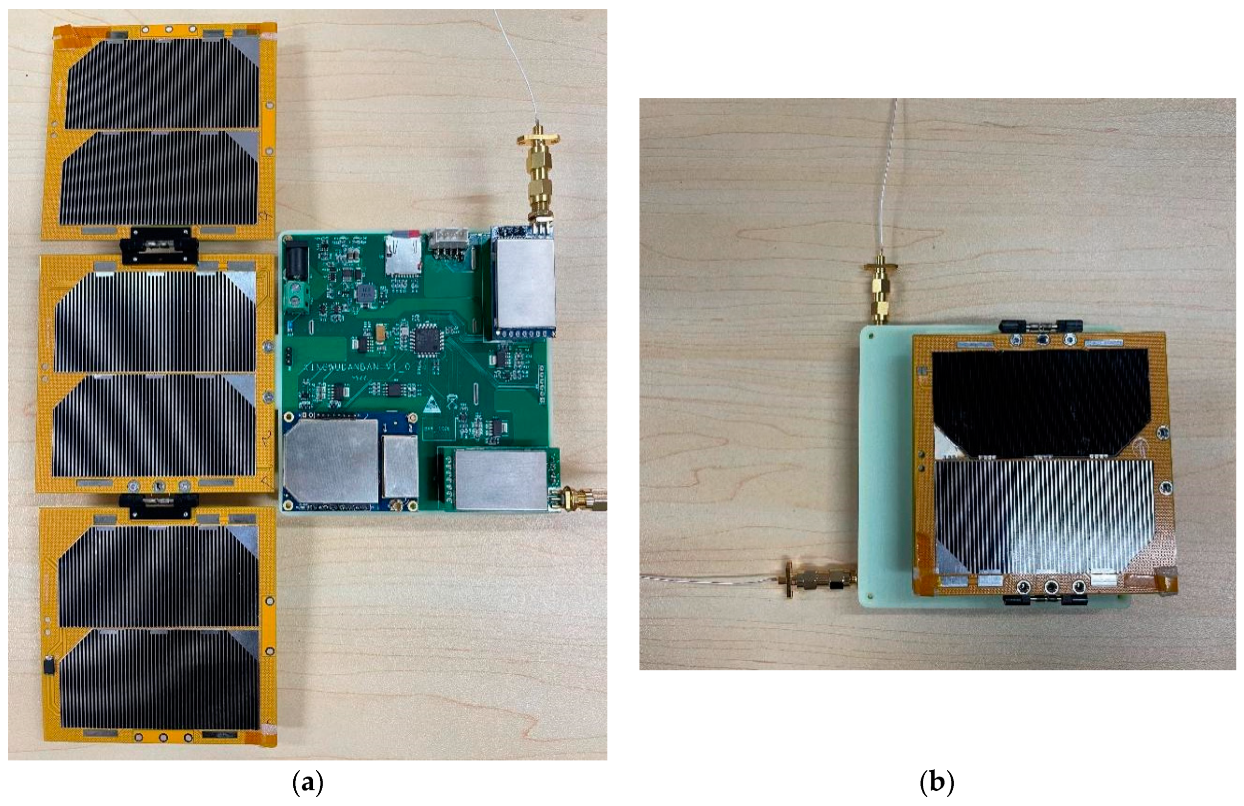
Building upon the aforementioned design principles, a prototype of this single-board satellite was developed using established commercial industrial modules, as depicted in Figure 9. STM32F405RGT6 produced by STMicroelectronics was selected as the chip for the control and data processing unit, with an internal FLASH capacity of 1024 KB. In addition, the external FLASH chip used the SST26VF032B chip produced by Microchip, and the NOR FLASH architecture chip had a capacity of 8 MB. The communication unit utilized wireless serial modules based on the SX1278 and SI4463 RF chips, respectively, while the GNSS unit consistently employed the high-dynamic GNSS module from the Company of OLinkstar (Beijing, China). The solar sailboard comprised six triple-junction GaAs solar cells, with the power circuit integrating one 18650 battery and a BQ24072 charge management chip produced by Texas Instruments (Dallas, TX, USA).

Figure 9.
Photos of the single-board satellite prototype in deployed (a) and stowed (b) states.
As demonstrated in Table 6, tests conducted on this novel prototype revealed that the transmit power of the single-board satellite’s communication unit was 27 dBm. Its receiving sensitivity could achieve −120 dBm with a peak power consumption of 3.2 W, satisfying both terrestrial communication and energy requirements. The prototype boasted a mass of 267 g and dimensions of 11 × 10.5 × 4 cm. It not only possessed independent ground communication capabilities but also successfully demonstrated the function of on-orbit operational mode switching. Such attributes rendered it competent to seamlessly undertake predefined observation tasks and potential future expanded observations.
6.2. Verification of Online Reconfiguration Functionality
To assess the designed single-board satellite’s capability to flexibly shift its online detection task modes, a foundational verification of its online reconfiguration function was conducted in a laboratory setting.
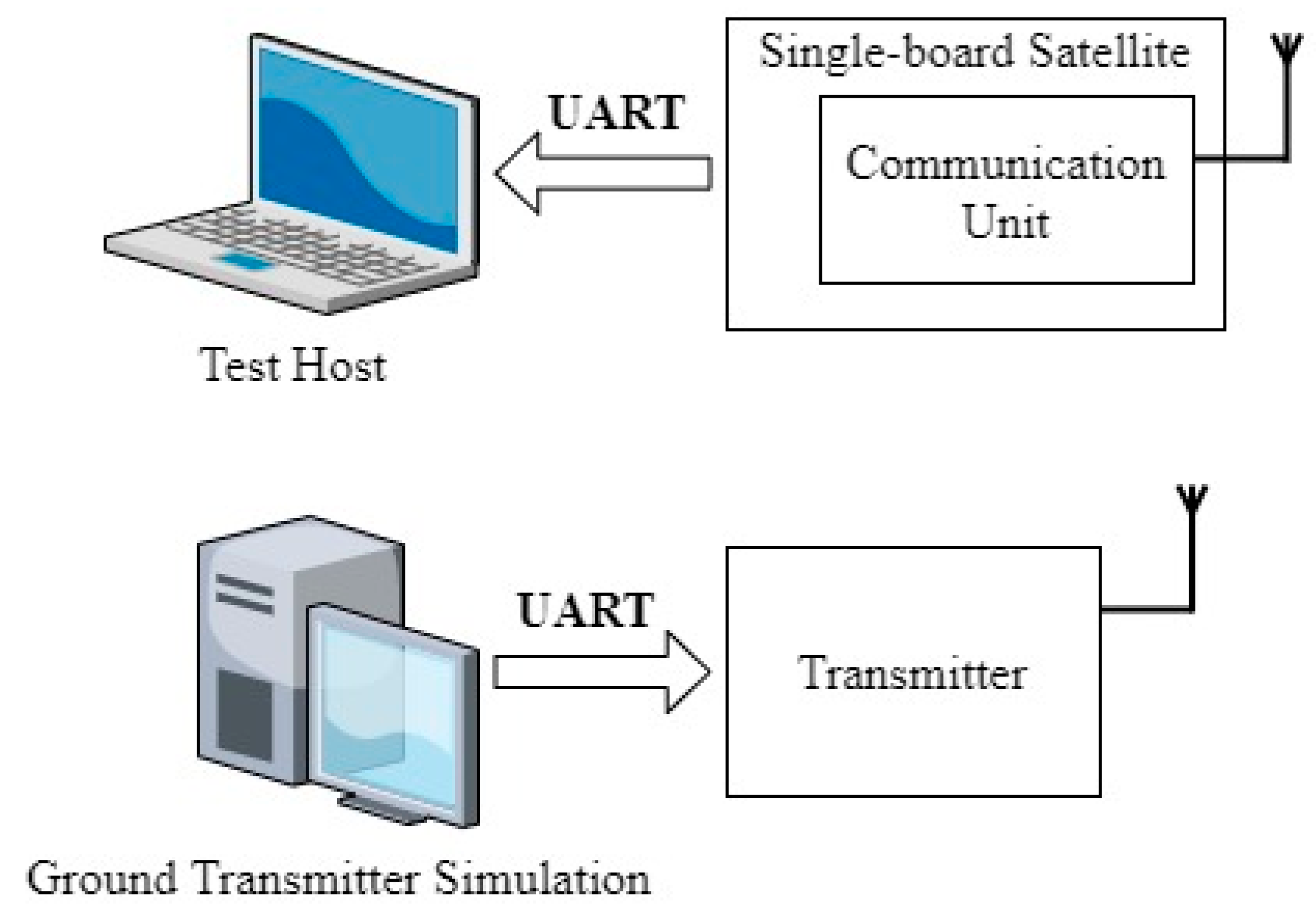
An experimental environment tailored to verify the reconfiguration function of the aforementioned single-board satellite’s hardware design was established, as illustrated in Figure 10. One computer was connected to the data transmission transmitter to simulate the ground station’s transmission end. Concurrently, another computer was linked via a serial port to the single-board satellite to monitor the software operation post online reconfiguration.
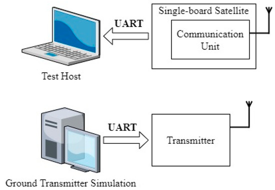
Figure 10.
Schematic of the ground test environment.
Hypothetically, if the ionospheric occultation detection mode currently executed on the satellite were to be altered via commands sent from the computer simulating the ground transmission end to atmospheric density detection mode, the success of this transition would be ascertained by observing changes in the output data from the test host monitoring the single-board satellite’s downlinked data.
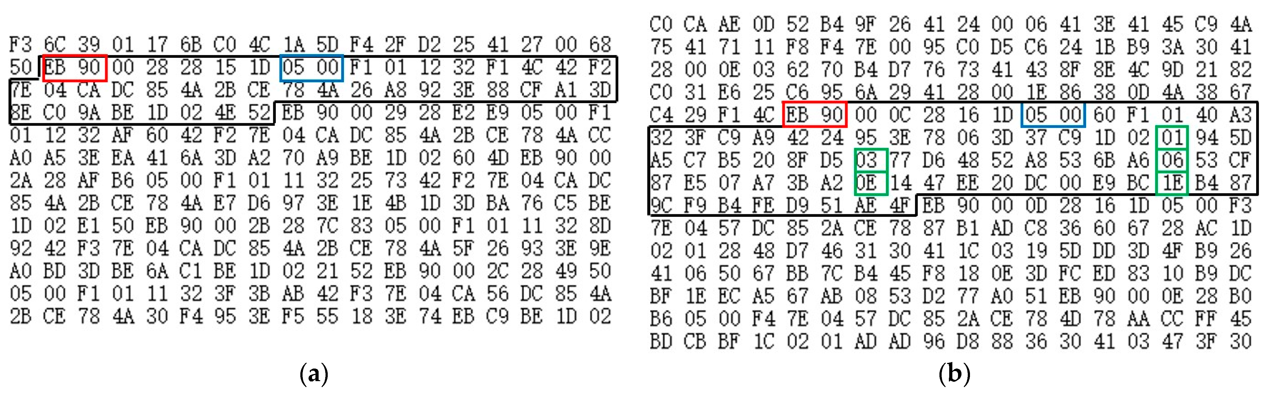
Before the software’s online reconfiguration, the output data format resembled that encased in the black box in Figure 11a. The red box represents the header of each data frame, and from the blue box, it is evident that the number of visible satellites at that time was five. Subsequently, the single-board satellite output observation values for each visible navigation satellite, where the green box indicates the satellite’s sequence number, followed by 4 bytes of pseudo-range information and carrier phase details.
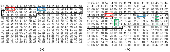
Figure 11.
Output of navigation satellite positioning information received by the satellite, including the received data before (a) and after reconfiguration (b).
Upon completion of the software’s online reconfiguration, the data format for the detection task mode output can be observed within the black box in Figure 11b. The 2 bytes of data inside the red box serve as the header information for each data frame; the blue box, from left to right, indicates a total of five visible satellites and a stable positioning status.
Thus, via these tests, it was confirmed that the single-board satellite can successfully navigate the rudimentary software reconfiguration procedures, thereby achieving a switch in its onboard software’s detection tasks, validating its feasibility.
A comparative analysis of the prototype’s specifications, alongside those of typical domestic and international very small satellites [12,13,14,15], is presented in Table 7. The table reveals that the single-board satellite proposed in this paper can markedly reduce the size and mass while achieving online software reconfiguration and independent ground communication functionalities.
Table 7.
Comparison between the single-board satellite prototype and other very small satellites.
7. Conclusions
In response to the emergent requirements of advanced space environment sensing, notably ultra-low orbit atmospheric density measurements and swift ionospheric occultation detection, a novel approach to single-board satellite design, capable of in-orbit reconfiguration, was astutely proposed. This research particularly delved into pivotal challenges concerning energy provisioning and consumption, as well as data transmission capacities. A prototype was meticulously crafted based on the conceptual design, and its on-orbit reconfiguration capabilities were rigorously validated. The newly introduced microsatellite structure, characterized by its compactness, reduced weight, minimized power demands, autonomous communication, and adaptable software reconfiguration, presents a promising avenue for innovations in ultra-low orbit space environment reconnaissance.
Author Contributions
Conceptualization, C.T. and X.H.; methodology, C.T. and F.W.; software, Y.W.; validation, Y.W. and C.T.; formal analysis, Y.W. and C.T.; investigation, Y.W.; resources, C.T. and F.W.; writing—original draft preparation, Y.W.; writing—review and editing, Y.W. and C.T.; funding acquisition, X.H. All authors have read and agreed to the published version of the manuscript.
Funding
This research was funded by the National Natural Science Foundation of China (Grant No. 12241101, 42174192). The APC was funded by the National Space Science Center, Chinese Academy of Sciences.
Data Availability Statement
No new data were created or analyzed in this study. Data sharing is not applicable to this article.
Conflicts of Interest
The authors declare no conflict of interest.
References
- Luo, B.X.; Wang, R.L.; Liu, W.; Yan, R.D.; Ren, T.L.; Ren, S.Y.; Liu, S.Q.; Lei, J.H. Analysis of the space environment where “Star Chain” satellite was destroyed by geomagnetic storm. Space Int. 2022, 5, 35–39. [Google Scholar]
- Davies, K.; Smith, E.K. Ionospheric effects on satellite land mobile systems. IEEE Antennas Propag. Mag. 2002, 44, 24–31. [Google Scholar] [CrossRef]
- Liu, Y.Y. Analysis of orbital inclination changes for “Atmosphere No.1” balloon satellite. Acta Astron. Sin. 1995, 2, 200–207. [Google Scholar]
- Liu, W.; Luo, B.X.; Gong, J.C.; Wang, R.L.; Rong, J.G. Study on dynamic correction model of thermospheric atmospheric density. Spacecr. Environ. Eng. 2023, 40, 213–219. [Google Scholar]
- Yang, H.L.; Wang, Y.N.; Dou, X.H.; Li, X.Y. “Force Rocket” No.1 Technology and Innovation. Aerosp. China 2023, 3, 14–18. [Google Scholar]
- Fish, C.S.; Swenson, C.M.; Crowley, G.; Barjatya, A.; Neilsen, T.; Gunther, J.; Azeem, I.; Pilinski, M.; Wilder, R.; Allen, D.; et al. Design, development, implementation, and on-orbit performance of the dynamic ionosphere CubeSat experiment mission. Space Sci. Rev. 2014, 181, 61–120. [Google Scholar] [CrossRef]
- Liu, W.; Liu, S.Q.; Gong, J.C.; Wang, R.L.; Rong, J.G. Near-space free-fall detection simulation analysis. Equip. Environ. Eng. 2020, 17, 1–7. [Google Scholar]
- Shi, D.B.; Hu, X.; Tu, C.; Wei, F.; Wang, X.Y. Near-space environmental sounding rocket expanded free-fall detection technology. Equip. Environ. Eng. 2018, 15, 89–92. [Google Scholar]
- Wu, X.C.; Hu, X.; Zhang, X.X.; Wickert, J. Ionospheric GPS occultation observation correction TEC inversion method. Chin. J. Geophys. 2006, 2, 328–334. [Google Scholar]
- Lin, Z.; Niu, H.; An, K.; Wang, Y.; Zheng, G.; Chatzinotas, S.; Hu, Y. Refracting RIS Aided Hybrid Satellite-Terrestrial Relay Networks: Joint Beamforming Design and Optimization. IEEE Trans. Aerosp. Electron. Syst. 2022, 58, 3717–3724. [Google Scholar] [CrossRef]
- Lin, Z.; Lin, M.; Champagne, B.; Zhu, W.P.; Al-Dhahir, N. Secrecy-Energy Efficient Hybrid Beamforming for Satellite-Terrestrial Integrated Networks. IEEE Trans. Commun. 2021, 69, 6345–6360. [Google Scholar] [CrossRef]
- An, K.; Lin, M.; Ouyang, J.; Zhu, W.P. Secure Transmission in Cognitive Satellite Terrestrial Networks. IEEE J. Sel. Areas Commun. 2016, 34, 3025–3037. [Google Scholar] [CrossRef]
- Lin, Z.; An, K.; Niu, H.; Hu, Y.; Chatzinotas, S.; Zheng, G.; Wang, J. SLNR-Based Secure Energy Efficient Beamforming in Multibeam Satellite Systems. IEEE Trans. Aerosp. Electron. Syst. 2023, 59, 2085–2088. [Google Scholar] [CrossRef]
- Su, R.F.; Zhang, K.K.; Song, H.W. Summarization of very small satellite development. Spacecr. Eng. 2013, 22, 104–111. [Google Scholar]
- Barnhart, D.J.; Vladimirova, T.; Sweeting, M.N. Verysmall-satellite design for distributed space missions. J. Spacecr. Rockets 2007, 44, 1294–1306. [Google Scholar] [CrossRef]
- San Luis Obispo, C.A. CubeSat Design Specification. 2023. Available online: https://static1.squarespace.com/static/5418c831e4b0fa4ecac1bacd/t/5f24997b6deea10cc52bb016/1596234122437/CDS+REV14+2020-07-31+DRAFT.pdf (accessed on 20 April 2023).
- Li, J.F. Research on On-Board Software Reconfiguration Technology of CubeSat. Master’s Thesis, Nanjing University of Science and Technology, Beijing, China, 2019. [Google Scholar]
- Barnhart, D.J.; Vladimirova, T.; Sweeting, M.N. Satellite miniaturization techniques for space sensor networks. J. Spacecr. Rocket. 2009, 46, 469–472. [Google Scholar] [CrossRef]
- Barnhart, D.J.; Vladimirova, T.; Baker, A.M.; Sweeting, M.N. A low-cost femtosatellite to enable distributed space missions. Acta Astronaut. 2009, 64, 1123–1143. [Google Scholar] [CrossRef]
- McVittie, G.; Kumar, K. Design of a COTS Femtosatellite and Mission. In Proceedings of the AIAA SPACE 2007 Conference & Exposition, Long Beach, CA, USA, 18–20 September 2007. [Google Scholar]
- Yang, L.; Guo, J.; Fan, C.; Song, X.; Wu, S.; Zhao, Y. The design and experiment of stardust femto-satellite. Acta Astronaut. 2020, 174, 72–81. [Google Scholar] [CrossRef]
- Jones, M.L.; Peterson, W.J. Falling Sphere Measurements, 30 to 120 km. Meteorol. Monogr. 1968, 8, 176–189. [Google Scholar]
- Liou, Y.A.; Pavelyev, A.G.; Liu, S.F.; Pavelyev, A.A.; Yen, N.; Huang, C.Y.; Fong, C.J. FORMOSAT-3/COSMIC GPS Radio Occultation Mission: Preliminary Results. IEEE Trans. Geosci. Remote Sens. 2007, 45, 3813–3826. [Google Scholar] [CrossRef]
- Ludwig-Barbosa, V.; Sievert, T.; Carlström, A.; Pettersson, M.I.; Vu, V.T.; Rasch, J. Supervised Detection of Ionospheric Scintillation in Low-Latitude Radio Occultation Measurements. Remote Sens. 2021, 13, 1690. [Google Scholar] [CrossRef]
- GJB 5421-2005; Methods for Calculation and Calibration of Satellite-Earth Data Transmission Link. Commission of Science, Technology and Industry for National Defense: Beijing, China, 2005.
- Wang, M.Y. Satellite remote sensing data link design. Space Electron. Technol. 2003, 2, 1–3+36. [Google Scholar]
- Fan, C.X.; Cao, L.N. Principles of Communications, 7th ed.; National Defense Industry Press: Beijing, China, 2013. [Google Scholar]
- Mao, Y.; Song, X.Y.; Jia, X.L.; Wu, X.B. Earth Eclipse Status Analysis of Beidou Navigation Satellites. Acta Geo-Daet. Cartogr. Sin. 2014, 43, 353–359. [Google Scholar]
- Sheng, T.; Bai, Y.Z.; Zhao, Y.; Chen, X.Q.; Chen, L.H. Energy balance simulation of board nano-satellite power system. J. Natl. Univ. Def. Technol. 2015, 37, 101–106. [Google Scholar]
- Lei, W.Y.; Ao, Z.L.; Zhou, Q.Q. In application programming (IAP) development based on STM32. Electron. Meas. Technol. 2015, 38, 62–66. [Google Scholar]


Disclaimer/Publisher’s Note: The statements, opinions and data contained in all publications are solely those of the individual author(s) and contributor(s) and not of MDPI and/or the editor(s). MDPI and/or the editor(s) disclaim responsibility for any injury to people or property resulting from any ideas, methods, instructions or products referred to in the content. |
© 2023 by the authors. Licensee MDPI, Basel, Switzerland. This article is an open access article distributed under the terms and conditions of the Creative Commons Attribution (CC BY) license (https://creativecommons.org/licenses/by/4.0/).