Metamaterial-Based Series-Fed Antenna with a High Gain and Wideband Performance for Millimeter-Wave Spectrum Applications


Abstract
:1. Introduction
- I
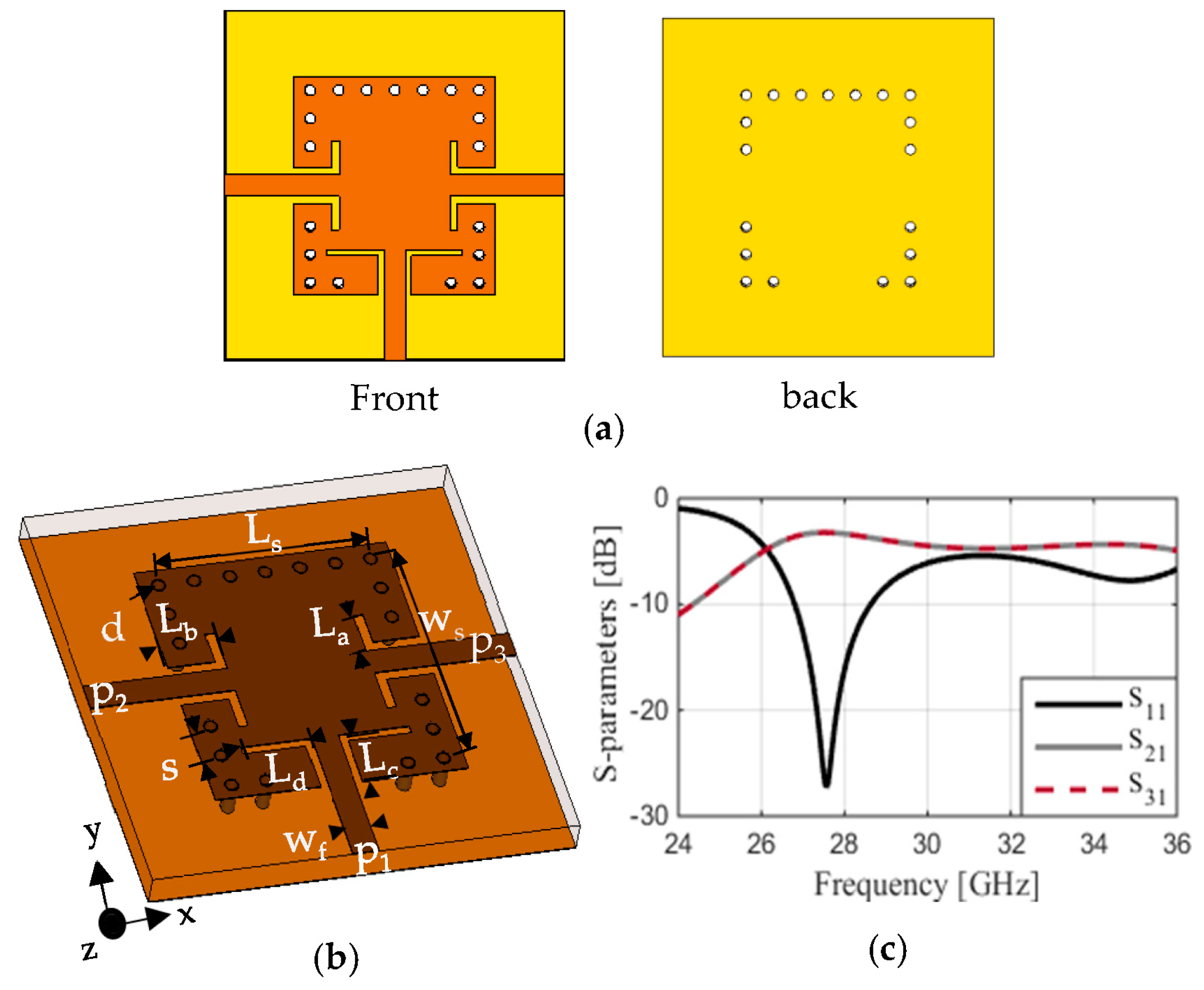
- The implementation of a power splitter at 27.5 GHz through the application of substrate-integrated waveguide (SIW);
- II
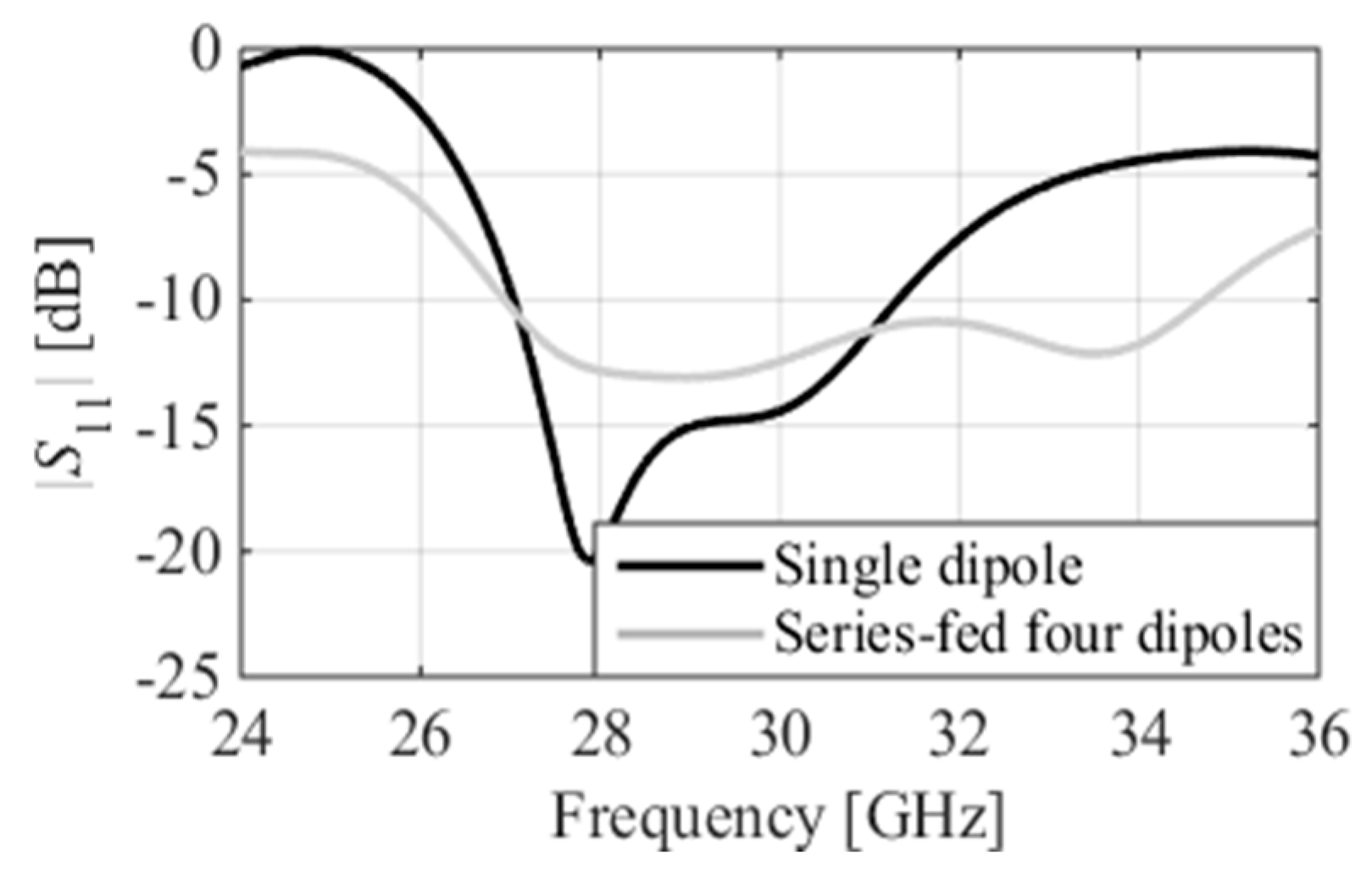
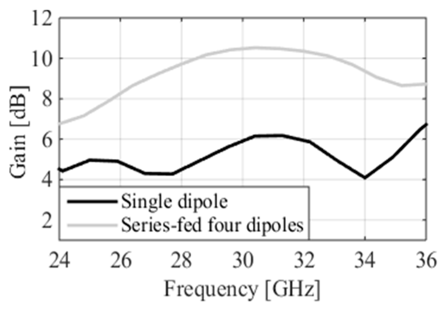
- Designing a compact four-element series-fed dipole antenna and integrating it with a power splitter to achieve a high gain, reaching a maximum of 10.5 dBi, along with a broad bandwidth spanning from 26.9 GHz to 34.75 GHz.
- III
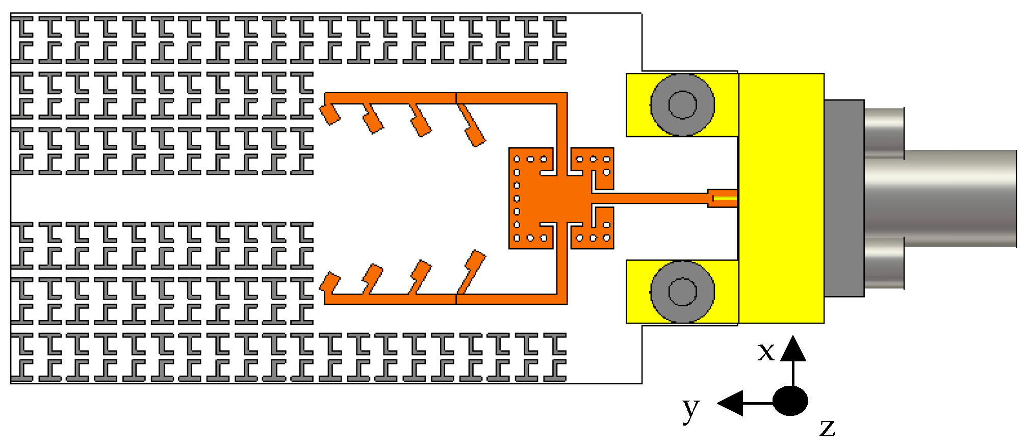
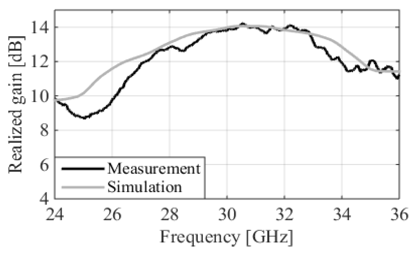
- Designing an MM structure operating within the MMW spectrum and integrating it with the series-fed antenna to further increase the gain to 14.1 dBi within the operational bandwidth.
2. SIW-Based Series-Fed Dipole
3. MM-Inspired High-Gain Antenna
4. Results
5. Conclusions
Author Contributions
Funding
Data Availability Statement
Conflicts of Interest
References
- Askari, H.; Hussain, N.; Sufian, M.A.; Lee, S.M.; Kim, N. A Wideband Circularly Polarized Magnetoelectric Dipole Antenna for 5G Millimeter-Wave Communications. Sensors 2022, 22, 2338. [Google Scholar] [CrossRef]
- Ouamri, M.A.; Ote¸steanu, M.E.; Isar, A.; Azni, M. Coverage, Handoff and cost optimization for 5G Heterogeneous Network. Phys. Commun. 2020, 39, 101037. [Google Scholar] [CrossRef]
- Ouamri, M.A. Stochastic geometry modeling and analysis of downlink coverage and rate in small cell network. Telecommun. Syst. 2021, 77, 767–779. [Google Scholar] [CrossRef]
- Esmail, B.A.F.; Koziel, S. Design and optimization of metamaterial-based dual-band 28/38 GHz 5G MIMO antenna with modified ground for isolation and bandwidth improvement. IEEE Antennas Wirel. Propag. Lett. 2023, 22, 1069–1073. [Google Scholar] [CrossRef]
- Ibrahim, A.A.; Zahra, H.; Dardeer, O.M.; Hussain, N.; Abbas, S.M.; Abdelghany, M.A. Slotted Antenna Array with Enhanced Radiation Characteristics for 5G 28 GHz Communications. Electronics 2022, 11, 2664. [Google Scholar] [CrossRef]
- Zhang, P.; Yang, B.; Yi, C.; Wang, H.; You, X. Measurement-based 5G millimeter-wave propagation characterization in vegetated suburban macrocell environments. IEEE Trans. Antennas Propag. 2020, 68, 5556–5567. [Google Scholar] [CrossRef]
- Barb, G.; Danuti, F.; Ouamri, M.A.; Otesteanu, M. Analysis of Vegetation and Penetration Losses in 5G mmWave Communication Systems. In Proceedings of the 2022 International Symposium on Electronics and Telecommunications (ISETC), Timisoara, Romania, 10–11 November 2022. [Google Scholar]
- Hwang, I.-J.; Oh, J.-I.; Jo, H.-W.; Kim, K.-S.; Yu, J.-W.; Lee, D.-J. 28 GHz and 38 GHz Dual-Band Vertically Stacked Dipole Antennas on Flexible Liquid Crystal Polymer Substrates for Millimeter-Wave 5G Cellular Handsets. IEEE Trans. Antennas Propag. 2022, 70, 3223–3236. [Google Scholar] [CrossRef]
- Ding, K.; Leenaerts, D.M.; Gao, H. A 28/38 GHz Dual-Band Power Amplifier for 5G Communication. IEEE Trans. Microw. Theory Tech. 2022, 70, 4177–4186. [Google Scholar] [CrossRef]
- Lugo, D.C.; Ramirez, R.A.; Wang, J.; Weller, T.M. Multilayer dielectric end-fire antenna with enhanced gain. IEEE Antennas Wirel. Propag. Lett. 2018, 17, 2213–2217. [Google Scholar] [CrossRef]
- Liu, H.; Tian, H.; Liu, L.; Feng, L. Co-design of wideband filtering dielectric resonator antenna with high gain. IEEE Trans. Circuits Syst. II Express Briefs 2022, 69, 1064–1068. [Google Scholar] [CrossRef]
- Shi, C.; Zou, J.; Gao, J.; Liu, C. Gain Enhancement of a Dual-Band Antenna with the FSS. Electronics 2022, 11, 2882. [Google Scholar] [CrossRef]
- Esmail, B.A.F.; Majid, H.A.; Dahlan, S.H.; Abidin, Z.Z.; Rahim, M.K.A.; Abdullah, M.A.; Jusoh, M. Antenna beam tilting and gain enhancement using novel metamaterial structure at 28 GHz. In Proceedings of the 2018 IEEE International RF and Microwave Conference (RFM), Penang, Malaysia, 17–19 December 2018. [Google Scholar]
- Desai, A.; Tsao, Y.F.; Hsu, H.T. High gain substrate integrated waveguide antenna with enhanced bandwidth for millimeter-wave wireless network applications. Wirel. Netw. 2023, 29, 2251–2260. [Google Scholar] [CrossRef]
- Zhu, S.; Liu, H.; Chen, Z.; Wen, P. A compact gain-enhanced Vivaldi antenna array with suppressed mutual coupling for 5G mmWave application. IEEE Antennas Wirel. Propag. Lett. 2018, 17, 776–779. [Google Scholar] [CrossRef]
- Wang, J.; Zhao, X.; Ye, Y.; Liu, S. A Millimeter-Wave Ultrawideband Tightly Coupled Dipole Array Antenna for Vehicle Communication. IEEE Antennas Wirel. Propag. Lett. 2022, 21, 2135–2139. [Google Scholar] [CrossRef]
- Mao, C.-X.; Khalily, M.; Xiao, P.; Brown, T.W.C.; Gao, S. Planar Sub-Millimeter-Wave Array Antenna with Enhanced Gain and Reduced Sidelobes for 5G Broadcast Applications. IEEE Trans. Antennas Propag. 2019, 67, 160–168. [Google Scholar] [CrossRef]
- Kadiyam, S.; Jhansi Rani, A. Design and Analysis of a High Gain Millimeter-Wave Antenna Array for Dual Purpose Applications. Wirel. Pers. Commun. 2023, 130, 593–607. [Google Scholar] [CrossRef]
- Liu, Y.-T.; Leung, K.W. 28 GHz Substrate-Integrated Filtering Dielectric Resonator Antenna Array. IEEE Trans. Antennas Propag. 2022, 70, 9900–9905. [Google Scholar] [CrossRef]
- Wang, H.; Kedze, K.E.; Park, I. A high-gain and wideband series-fed angled printed dipole array antenna. IEEE Trans. Antennas Propag. 2020, 68, 5708–5713. [Google Scholar] [CrossRef]
- Maurya, N.K.; Ammann, M.J.; Mcevoy, P. Series-fed omnidirectional mm-wave dipole array. IEEE Trans. Antennas Propag. 2023, 71, 1330–1336. [Google Scholar] [CrossRef]
- Liu, Y.; Yagoub, M.C.E. Compact omnidirectional millimeter-wave antenna array fed in series by a novel feed network. IEEE Trans. Antennas Propag. 2022, 69, 7604–7612. [Google Scholar] [CrossRef]
- Duddu, S.K.; Kumar, J. High-Gain Series-Fed-Planar Millimetre-Wave Franklin Antenna Array. Arab. J. Sci. Eng. 2023, 1–11. [Google Scholar] [CrossRef]
- Ma, T.; Ai, J.; Shen, M.; Joines, W.T. Design of novel broadband endfire dipole array antennas. IEEE Antennas Wirel. Propag. Lett. 2017, 16, 2935–2938. [Google Scholar] [CrossRef]
- Esmail, B.A.F.; Koziel, S.; Szczepanski, S. Overview of planar antenna loading metamaterials for gain performance enhancement: The two decades of progress. IEEE Access 2022, 10, 27381–27403. [Google Scholar] [CrossRef]
- Wani, Z.; Abegaonkar, M.P.; Koul, S.K. High-low-epsilon biaxial anisotropic lens for enhanced gain and aperture efficiency of a linearly polarized antenna. IEEE Trans. Antennas Propag. 2020, 68, 8133–8138. [Google Scholar] [CrossRef]
- Jeong, M.; Hussain, N.; Abbas, A.; Rhee, S.Y.; Lee, S.M.; Gil, S.-K.; Kim, N. Performance improvement of microstrip patch antenna using a novel double-layer concentric rings metaplate for 5G millimeter wave applications. Int. J. RF Microw. Comput.-Aided Eng. 2020, 31, e22509. [Google Scholar] [CrossRef]
- Esmail, B.A.F.; Koziel, S. Design and Optimization of Metamaterial-Based 5G Millimeter Wave Antenna for Gain Enhancement. IEEE Trans. Circuits Syst. II Express Briefs 2023, 70, 3348–3352. [Google Scholar] [CrossRef]
- Chen, X.P.; Wu, K.; Drolet, D. Substrate integrated waveguide filter with improved stopband performance for satellite ground terminal. IEEE Trans. Microw. Theory Tech. 2009, 57, 674–683. [Google Scholar] [CrossRef]
- Ta, S.X.; Choo, H.; Park, I. Broadband printed-dipole antenna and its arrays for 5G applications. IEEE Antennas Wirel. Propag. Lett. 2017, 16, 2183–2186. [Google Scholar] [CrossRef]
- Chen, X.; Grzegorczyk, T.M.; Wu, B.I.; Pacheco, J., Jr.; Kong, J.A. Robust method to retrieve the constitutive effective parameters of metamaterials. Phys. Rev. E 2004, 70, 016608. [Google Scholar] [CrossRef]
- Li, D.; Wang, J.A.; Yu, Y.; Liu, Y.; Chen, Z.; Yang, L. Substrate integrated waveguide-based complementary split-ring resonator and its arrays for compact dual-wideband bandpass filter design. Int. J. RF Microw. Comput.-Aided Eng. 2021, 31, e22504. [Google Scholar] [CrossRef]
- Zhao, L.; Li, Y.; Chen, Z.M.; Liang, X.H.; Wang, J.; Shen, X.; Zhang, Q. A band-pass filter based on half-mode substrate integrated waveguide and spoof surface plasmon polaritons. Sci. Rep. 2019, 9, 13429. [Google Scholar] [CrossRef] [PubMed]
- Pawar, S.S.; Shandilya, M.; Chaurasia, V. Parametric evaluation of microstrip log periodic dipole array antenna using transmission line equivalent circuit. Eng. Sci. Technol. Int. J. 2017, 20, 1260–1274. [Google Scholar] [CrossRef]
- Esmail, B.A.F.; Majid, H.B.; Dahlan, S.H.; Abidin, Z.Z.; Rahim, M.K.; Jusoh, M. Planar antenna beam deflection using low-loss metamaterial for future 5G applications. Int. J. RF Microw. Comput.-Aided Eng. 2019, 29, e21867. [Google Scholar] [CrossRef]
- Hosoya, K.; Prasad, N.; Ramachandran, K.; Orihashi, N.; Kishimoto, S.; Rangarajan, S.; Maruhashi, K. Multiple sector ID capture (MIDC): A novel beamforming technique for 60-GHz band multi-Gbps WLAN/PAN systems. IEEE Trans. Antennas Propag. 2015, 63, 81–96. [Google Scholar] [CrossRef]


| Symbol | Description |
|---|---|
| SIW’s resonant frequency | |
| Leff | Effective length of the SIW |
| Weff | Effective width of the SIW |
| LS | Length of the SIW |
| WS | Width of the SIW |
| εr | Dielectric constant of the substrate |
| d | Diameter of the via hole |
| s | The spacing between the vias |
| c | Speed of light |
| n | Refractive index |
| z | Impedance |
| ko | Wavenumber |
| t | Thickness of the MM structure |
| img | Imaginary component of the complex number |
| Re | Real component of the complex number |
| m | Branch index of n |
| Ref. | Antenna Structure (Size mm3) | Substrate (εr) | Frequency (GHz) | Max. Gain (dB) | Aperture Efficiency (%) | Method |
|---|---|---|---|---|---|---|
| [15] | Vivaldi antenna (28.82 × 60 × 0.787) | Rogers RT 5880 (2.2) | 25.5 | 11.3 | 8.58 | 1 × 8 array |
| [16] | Dipole antenna (112 × 50 × 3) | Taconic-TLY (2.2) | 18 | 8 | 2.5 | 1 × 8 array |
| [17] | Dipole antenna (66 × 15 × 0.3) | Rogers RT 5880 (2.2) | 26 | 11 | 13.4 | 1 × 8 array |
| [18] | Patch (13.4 × 50.8 × 0.508) | Rogers RT 5880 (2.2) | 31 | 14 | 27.4 | 1 × 4 array |
| [19] | DRA (20.7 × 21.2 × 1.5) | Rogers RT/duroid 6010.2LM (2.2) | 28 | 6.7 | 9.7 | 2 × 2 array on substrates of three layers |
| [20] | Dipole (10 × 36.5 × 0.2032) | RO4003C (3.38) | 28 | 10.9 | 30.7 | Series-fed eight-element dipole |
| [21] | Dipole (25 × 67 × 0.5) | RO5880 (2.2) | 28.5 | 10.3 | 5.6 | Series-fed six-element dipole |
| [22] | Dipole (10 × 59 × 0.203) | RO4003C (3.55) | 28 | 12.3 | 26.2 | Series-fed eight-element dipole |
| [23] | Patch (21 × 40.8 × 1.6) | Rogers RT 5880 (2.2) | 27.68 | 11.8 | 16.8 | Series-fed four-element patch |
| [26] | Patch (14.7 × 28 × 7) | Rogers 5870 (2.2) | 28 | 12.6 | 40.2 | Seven MM layers (3D structure) |
| [27] | Microstrip (18 × 22 × 16) | RO4003 (3.38) | 28 | 11.59 | 33.1 | One MM layer (3D structure) |
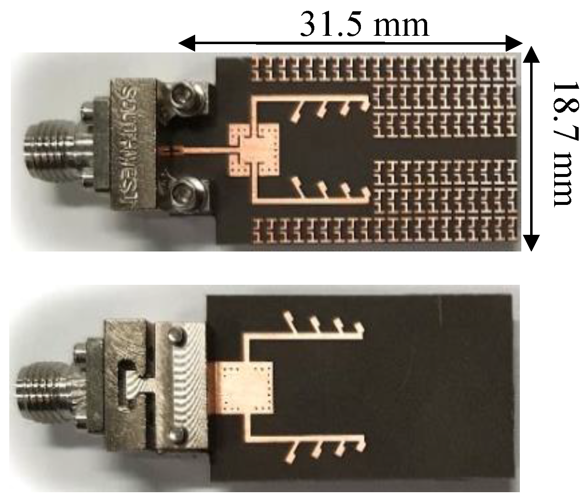
| This study | Dipole (31.5 × 18.7 × 0.508) | Rogers RT 5880 (2.2) | 30.5 | 14.1 | 36 | Series-fed + Etching the MMs on the antenna substrate |
Disclaimer/Publisher’s Note: The statements, opinions and data contained in all publications are solely those of the individual author(s) and contributor(s) and not of MDPI and/or the editor(s). MDPI and/or the editor(s) disclaim responsibility for any injury to people or property resulting from any ideas, methods, instructions or products referred to in the content. |
© 2023 by the authors. Licensee MDPI, Basel, Switzerland. This article is an open access article distributed under the terms and conditions of the Creative Commons Attribution (CC BY) license (https://creativecommons.org/licenses/by/4.0/).
Share and Cite
Esmail, B.A.F.; Koziel, S.; Isleifson, D. Metamaterial-Based Series-Fed Antenna with a High Gain and Wideband Performance for Millimeter-Wave Spectrum Applications. Electronics 2023, 12, 4836. https://doi.org/10.3390/electronics12234836
Esmail BAF, Koziel S, Isleifson D. Metamaterial-Based Series-Fed Antenna with a High Gain and Wideband Performance for Millimeter-Wave Spectrum Applications. Electronics. 2023; 12(23):4836. https://doi.org/10.3390/electronics12234836
Chicago/Turabian StyleEsmail, Bashar A. F., Slawomir Koziel, and Dustin Isleifson. 2023. "Metamaterial-Based Series-Fed Antenna with a High Gain and Wideband Performance for Millimeter-Wave Spectrum Applications" Electronics 12, no. 23: 4836. https://doi.org/10.3390/electronics12234836
APA StyleEsmail, B. A. F., Koziel, S., & Isleifson, D. (2023). Metamaterial-Based Series-Fed Antenna with a High Gain and Wideband Performance for Millimeter-Wave Spectrum Applications. Electronics, 12(23), 4836. https://doi.org/10.3390/electronics12234836