Article

Design of Orbital Angular Momentum Antenna Array for Generating High-Order OAM Modes

1
State Key Laboratory of Information Photonics and Optical Communications, School of Science, Beijing University of Posts and Telecommunications, Beijing 100876, China
2
Beijing Aerospace Zhongxin Technology Co., Ltd., Beijing 100195, China
3
Beijing Key Laboratory of Intelligent Telecommunication Software and Multimedia, Beijing University of Posts and Telecommunications, Beijing 100876, China
*
Author to whom correspondence should be addressed.
Electronics 2023, 12(24), 4891; https://doi.org/10.3390/electronics12244891
Submission received: 5 October 2023 / Revised: 17 November 2023 / Accepted: 2 December 2023 / Published: 5 December 2023
(This article belongs to the Section Microwave and Wireless Communications)

Abstract

:
Orbital angular momentum (OAM) modes can offer high density and high-capacity communication. The traditional phased array antenna can only produce a limited number of OAM beam modes l, usually less than half of the number of array elements (N): −N/2 < lmax < N/2. An OAM antenna array for generating high-order OAM modes is proposed in this letter. The proposed antenna array consists of a ring patch antenna that can generate vortex waves with OAM mode l = 1 or −1 and a phase-shifting feeding network. By adding different feed excitation signals to each element, the generated beam carries a higher-order mode: l = N or −N, breaking the previous limitations. Near-field measurements were conducted on antenna arrays composed of 3, 4, and 5 elements, revealing a high degree of correspondence between their phase distribution and radiation patterns with numerical simulation results. This alignment further substantiates the practical efficacy of this approach in significantly enhancing the generation of high-order OAM modes within antenna arrays. This advancement improves component utilization efficiency, reduces system complexity, and meets the high demands for spectral resources and channel capacity in future communication applications.

1. Introduction

Electromagnetic waves possess both linear momentum and angular momentum (AM) which comprises the spin angular momentum (SAM) and the orbital angular momentum (OAM) [1]. SAM is associated with circular polarization, while OAM carries a spatial phase factor ejlϕ, where l is the OAM mode number and ϕ is the azimuthal angle [2]. The wavefront of the OAM beam has a spiral phase structure, and its intensity distribution is annular [3]. For a fixed frequency, the OAM wave can generate an infinite number of orthogonal and independent OAM modes, which can modulate multiple signals to different modes to distinguish different independent channels [4]. Therefore, wireless communication based on vortex electromagnetic waves possesses the potential to increase communication capacity infinitely, effectively addressing issues of scarce spectrum resources and insufficient channel capacity. Moreover, it exhibits strong anti-interference ability and extremely high security [5]. Due to its unique properties, OAM has gained increasing attention and applications in various fields, including wireless communication, optical imaging, and other fields [6,7]. Since its initial proposal by Allen et al. [8], numerous methods have emerged in the field of wireless communication for generating OAM beams [9], including spiral phase plates [10,11], spiral reflectors [12], metasurfaces [13], and antenna arrays [14,15], etc. However, most of the OAM antenna design studies can only generate low-order mode OAM beams (i.e., l ≤ 4), and there are few studies on high-order. High-order mode OAM beam is very important in practical applications.
The orbital angular momentum vortex beam can be generated effectively by controlling the excitation phase of the array elements by using an array antenna, which is the most common method to generate high-order OAM modes [16]. Using enough linearly polarized or circularly polarized antennas as the array elements, OAM beams of any mode can be generated theoretically. N identical antenna elements are evenly placed on a circle to form an array, and signals with the same amplitude and appropriate phase shifts are provided for each element through the feed network. The phase angle of the feed excitation on the N-th array element is expressed as ϕn = 2/N. The number of elements in the array (N) determines the largest mode (l) generated by the array. The mode number is governed as per theory −N/2 < l < N/2 [17]. This indicates that to generate OAM waves with specific modes, an array composed of antennas with more than twice the mode number is required. This requirement undoubtedly results in excessively large antenna systems and increased complexity for generating high-order OAM beams.
In wireless communication, microstrip resonator antennas (patch antennas), are favored for their easy fabrication, low cost, and compact size with minimal radiation loss. Their small size and narrow bandwidth make them ideal for large scanning arrays, enhancing effectiveness. Particularly, microstrip antennas with ring-shaped resonators offer more benefits in complex systems compared to simpler geometries like rectangular or elliptical patches [18].
This study presents a solution by constructing a uniform circular array using ring microstrip resonator antennas capable of generating mode l = −1 or 1 OAM waves. Specific phase modulation is applied to the excitation of each element, resulting in high-order mode OAM waves with the same number of OAM modes as the number of antennas. Compared to traditional phased array antennas, this solution achieves the goal of reducing the number of antennas to generate the same high-order OAM modes, significantly lowering system complexity, and providing a blueprint for designing high-order mode OAM wave transmitters that effectively address spectrum scarcity and insufficient channel capacity.

2. Structural Design and Simulation

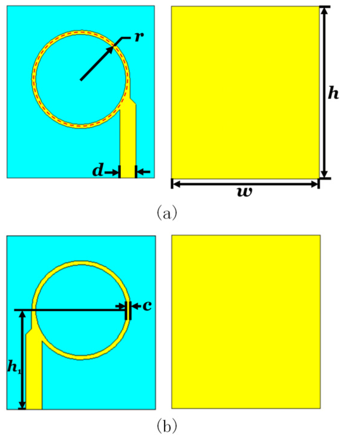
2.1. Ring Patch Antenna Generating First-Order OAM Wave

Based on the work of [19], we have designed and optimized a ring resonator-based patch antenna element as depicted in Figure 1, which is capable of generating OAM beams with mode l = −1 or 1. The sign of the beam is determined by the rotation direction of the surface current. The ring patch antenna consists of three layers: a radiating layer, a dielectric layer, and a metallic substrate. The radiating layer includes a ring-shaped patch and a feed line. The dielectric layer has a thickness of 2 mm and a dielectric constant of 2.65. The bottom metallic substrate measures 0.018 mm in thickness.
To achieve phase control, the circumference of the ring resonator-based patch antenna should be an integer multiple of the wavelength. The input feed signal oscillates in the ring resonator in which the new incident signal at the same working frequency resonates with the existing signal, while the signal oscillation at different frequencies is weakened due to the existence of phase difference. Therefore, the patch antenna based on the ring resonator has selective frequency characteristics [19]. Simultaneously, through the transmission of electromagnetic waves within the ring resonator, a continuous phase variation is formed within a range that is an integral multiple, which is a necessary condition for generating OAM beams. Considering the desired working frequency of 5.8 GHz, as well as factors such as appropriate resonance peak width, the structural parameters of the transmitter have been calculated and optimized, as shown in Figure 1. Specifically, the radius of the ring resonator, r, is set to 12 mm, the width and length of the substrate are respectively set to w = 36 mm and h = 42 mm, the height of the center of the ring resonator is h1 = 24 mm, the width of the feed line is d = 4 mm, and the width of the patch is c = 1 mm.
To validate the design and performance of the ring resonator-based patch antenna, we employed the commercial software CST Microwave Studio to model and simulate the structure. The simulated results of the reflection coefficient of the antenna with the operating frequency at 5.8 GHz were simulated as shown in Figure 2a, which displays a minimum reflection coefficient below −20 dB, indicating good impedance matching. Electric field and far-field monitors were established at 5.8 GHz to simulate the electric field phase distribution and far-field radiation pattern. The near-field mapping distance of phase distribution is 200 mm. The results are shown in Figure 2b,c. The phase distribution of the generated OAM beam presents a complete clockwise spiral, consistent with the characteristics of OAM waves with mode of l = −1. The intensity distribution exhibits a central depressed doughnut shape, corresponding to the physical property of lower energy at the center and higher energy at the edges of OAM waves. These results confirm that the designed antenna achieves an OAM beam with an l = −1 mode, aligning closely with the theoretical predictions. The same results can be obtained for the positive mode as well.

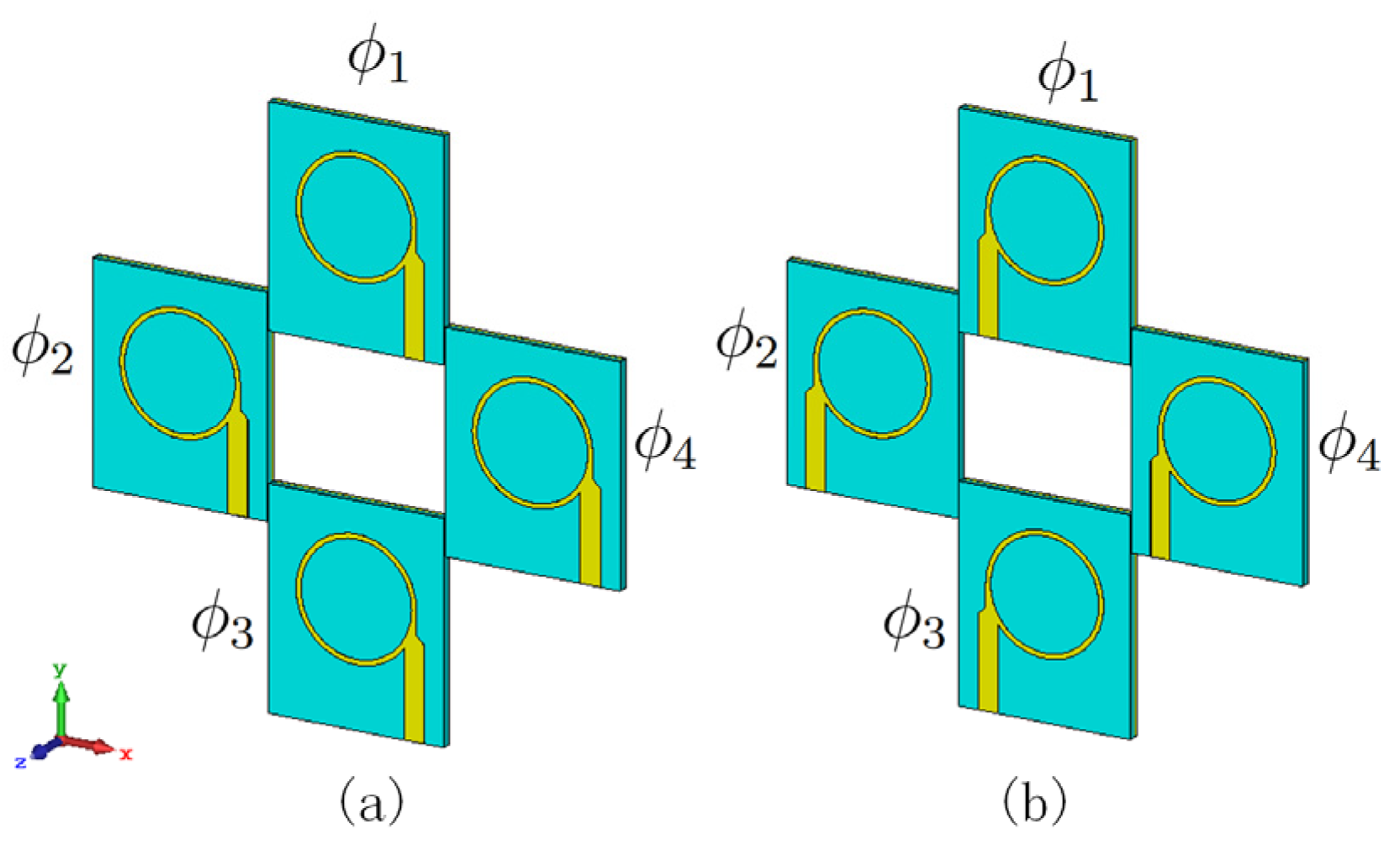
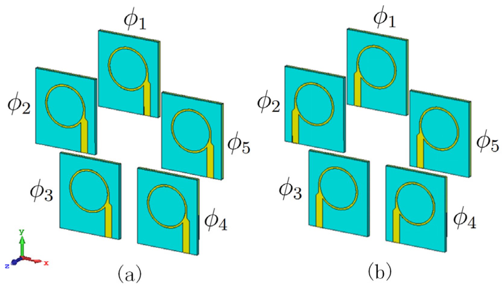
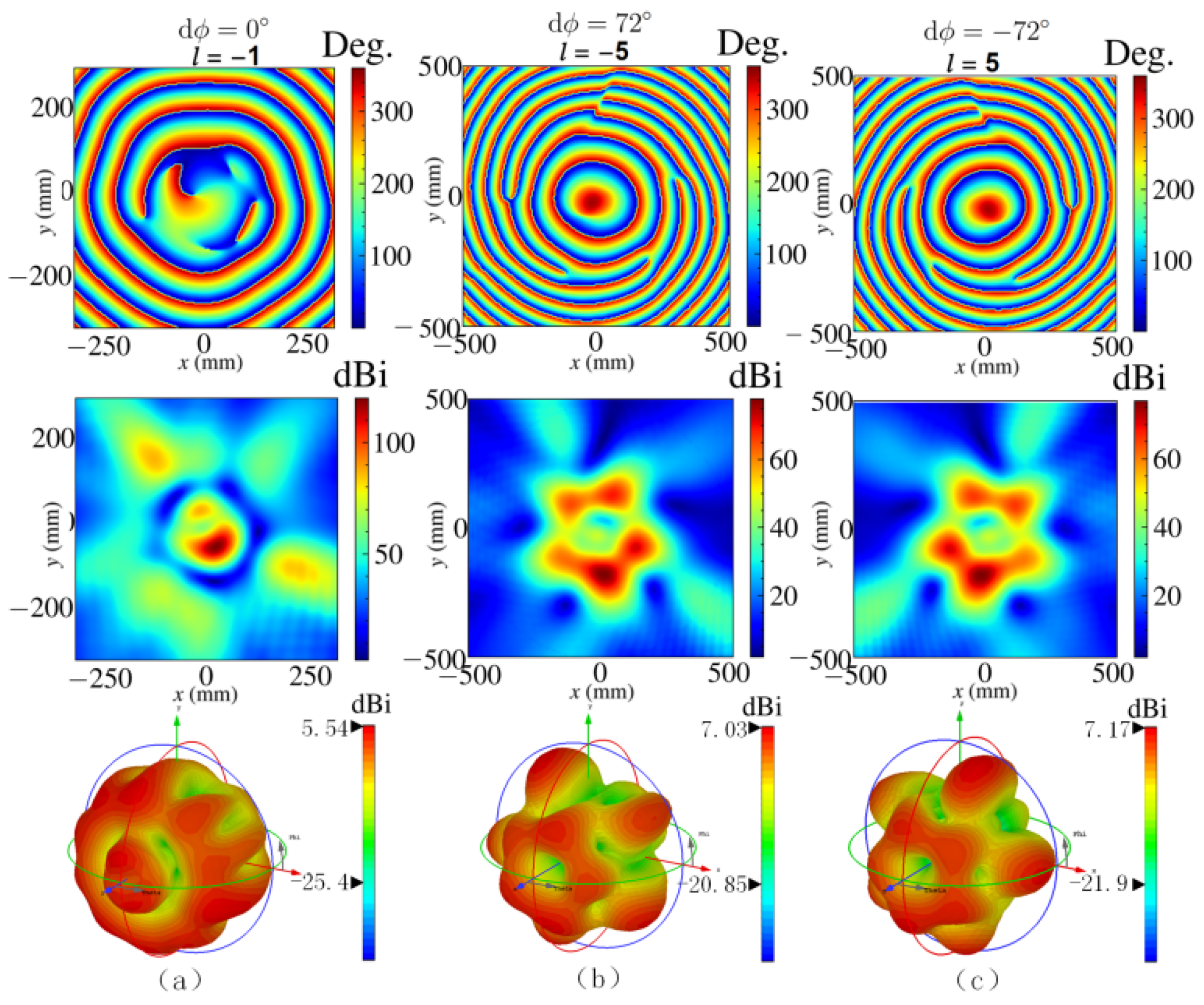
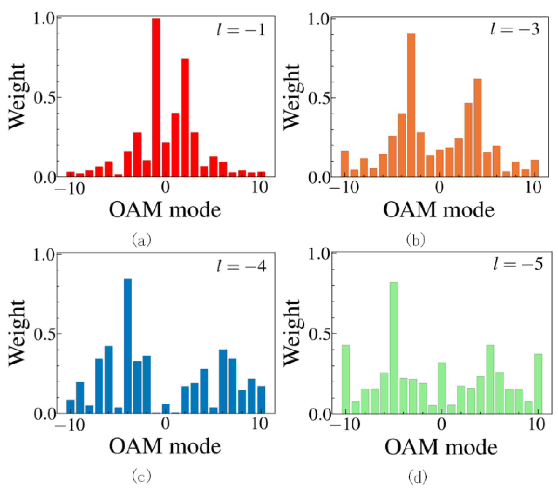
2.2. OAM Wave Array Antennas That Generate Higher-Order OAM Modes

Using the designed ring microstrip patch antenna mentioned above as the element, an antenna array is formed. As shown in Figure 3a, three OAM wave antenna elements carrying OAM mode l = −1 are uniformly distributed on a circle with a radius of R = 31 mm, and the angle between adjacent elements is θ = 120°. Each element is fed with equal amplitude and in-phase excitation signals. The time-domain finite integration technique (FITD) is employed using CST Microwave Studio for computational analysis. The simulated results of the 300 mm observation distance in Figure 4a demonstrate that the phased distribution generated by this antenna array exhibits a spiral pattern, corresponding to an OAM mode with l = −1. Slight disturbances can be observed in the directions of the three antenna units, possibly due to the superposition of multiple eigenstates resulting in mixed states. However, the overall pattern still forms a spiral. This represents the maximum OAM mode achievable by a conventional 3-antenna array with equal amplitude but different phase excitations. Similar results can be obtained for the negative states, but further elaboration is omitted here.
To enhance the modes of OAM waves generated by the array, modulation of the phase of the excitation signals is necessary. According to the phase conditions of the excitation signals that can generate OAM waves in traditional array antennas:
= −l·2π/N.
The phase difference of 2π/3 is obtained by substituting the parameters N = 3, l = −1 into the traditional three-antenna array. Therefore, the same amplitude of the excitation signal is added to the three antenna elements, with counterclockwise phase values of ϕ1 = 0°, ϕ2 = 120°, and ϕ3 = 240°. The simulated electric field results are shown in Figure 4b: the phase distribution of the electromagnetic waves radiated by the antenna array exhibits three clockwise spiral shapes, with no other modes at the center. This result indicates the generation of a single mode (l = −3) OAM electromagnetic wave. Similarly, by using three antenna elements with l = 1 to form the same circular array, as shown in Figure 3b, and adding excitation signals with the same amplitude and a phase difference of = ϕ3ϕ2 = ϕ2ϕ1 = −120°, the simulation results in Figure 4c clearly display the characteristics of OAM waves, specifically an OAM mode of l = 3. Both the near-field mapping distance of phase distributions is 300 mm.
Combining the results of the two simulations, the two 3-antenna arrays with opposite surface current rotation directions generate phase distributions with three spirals of opposite twisting directions. These patterns represent the generation of OAM electromagnetic waves with OAM modes l = 3 or −3. Based on these results, it can be inferred that by uniformly assembling individual ring patch antennas capable of generating OAM waves into a circular array with a certain radius and feeding them with a specific phase difference, OAM waves with a mode number equal to the number of antennas can be generated, achieving l = N or −N. To verify this idea, the number of elements in the antenna array is extended from 3 to 4 and 5, and corresponding simulations are conducted using CST. The array radius R was determined by conducting a comprehensive parameter scan in CST Microwave Studio. The phase distribution and radiation patterns were compared to select the most representative set that fully and clearly demonstrates the OAM mode.
As shown in Figure 5a, four antenna elements with OAM mode l = −1 are uniformly distributed on a circle with a radius of R = 35 mm, with adjacent elements having an angle of 90°. When the excitation signals received by these elements are of equal amplitude and phase, the simulated results are shown in Figure 6a, where the phase distribution still forms a clockwise spiral, indicating the generation of OAM waves carrying mode l = −1. The near-field mapping distance of phase distribution is 100 mm. While, when the phase difference of the excitation signal is = ϕ4ϕ3 = ϕ3ϕ2 = ϕ2ϕ1 = 90°, the simulated phase distribution in Figure 6b exhibits four perfect clock-wise spiral shapes, corresponding to the generation of OAM electromagnetic waves carrying the OAM mode l = −4. The opposite operation yields the result of l = 4, as shown in Figure 6c. The near-field mapping distance of phase distributions is 300 mm.
The same principle can also be verified with a circular array with a radius of R = 40 mm, composed of five OAM wave antenna elements. When the excitation signals for the array consisting of five l = −1 ring patch antennas, as depicted in Figure 7a, are of equal- amplitude and in-phase, the electric field phase pattern of 200 mm observation distance in the simulated result, as shown in Figure 8a, corresponds to a complete OAM mode l = −1. Clearly, the reverse structure would generate a mode l = 1 with opposite sign. When phase differences of = 2π/5 or −2π/5 are added in a counterclockwise direction to the elements in the array, the phase distributions of 300 mm observation distance of the two electromagnetic waves in Figure 8b,c exhibit five spirals with opposite twisting directions, and no other modes are present at the center. This confirms the generation of OAM waves with mode l = 5 or −5.
The purity of the OAM mode is important for measuring the state of OAM wave. The generated OAM beam can generally be regarded as a superposition of multiple OAM modes. According to the Fourier transform principle, the purity of each mode can be expressed as [20]:
p ( l ) = 1 2 π 0 2 π ψ ( ϕ ) d ϕ e j l ϕ
here, l denotes the modal component of the generated OAM beam, ψ represents the phase distribution, and ϕ denotes the azimuth angle [21,22]. The calculated results of mode purity based on this are shown in Figure 9, it can be observed that the spectral weight of the OAM mode l = −1 for the designed antenna unit is close to 1, indicating that the target OAM mode dominates the spectrum. This demonstrates that the proposed ring patch antenna element generates OAM beams with ideal high-mode purity. Furthermore, Figure 9b–d respectively display the spectral weights of the OAM modes carried by the OAM waves generated by 3, 4, and 5 antenna arrays composed of the aforementioned antenna elements. The spectral weights of their respective target OAM modes, l = −3, −4, and −5, are all above 0.8, much higher than the proportions of other redundant modes. This indicates that the antenna array performs well in generating OAM beams with high mode purity. These results strongly confirm the conclusion that phased arrays composed of OAM wave antennas as units can generate OAM waves with high-order OAM mode numbers equal to the number of antennas, i.e., l = N or −N.

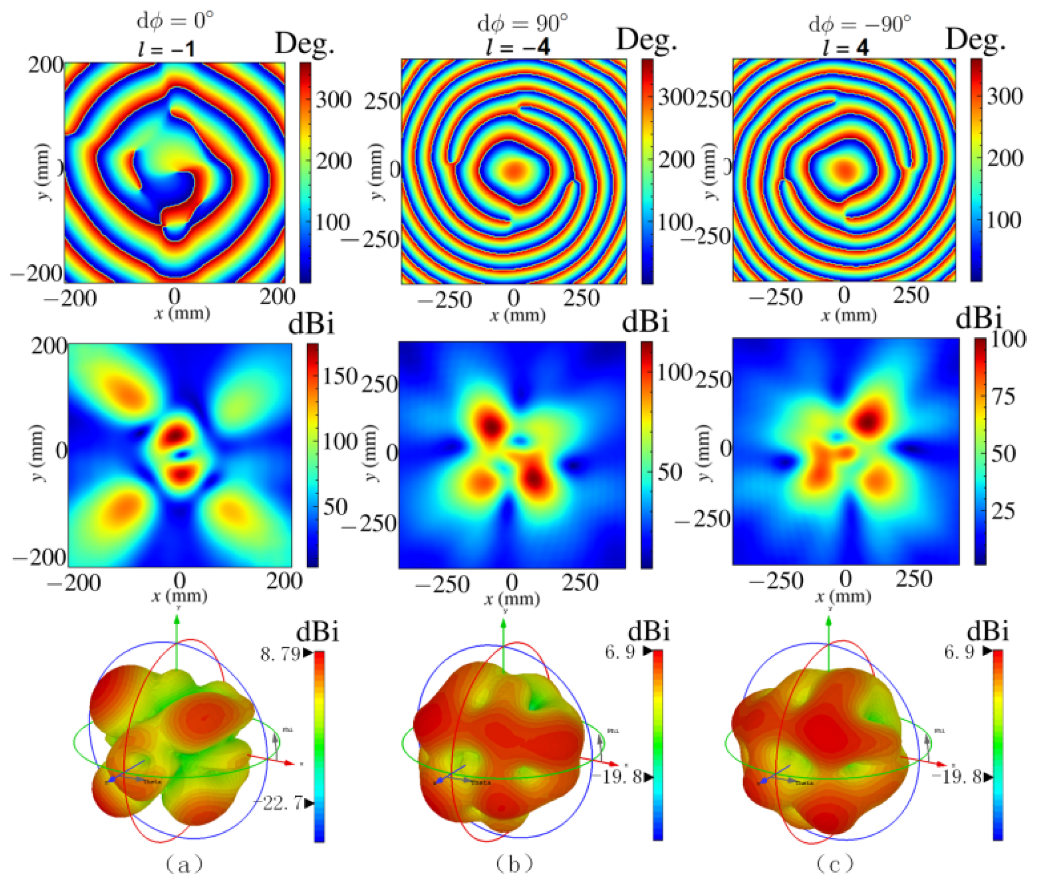
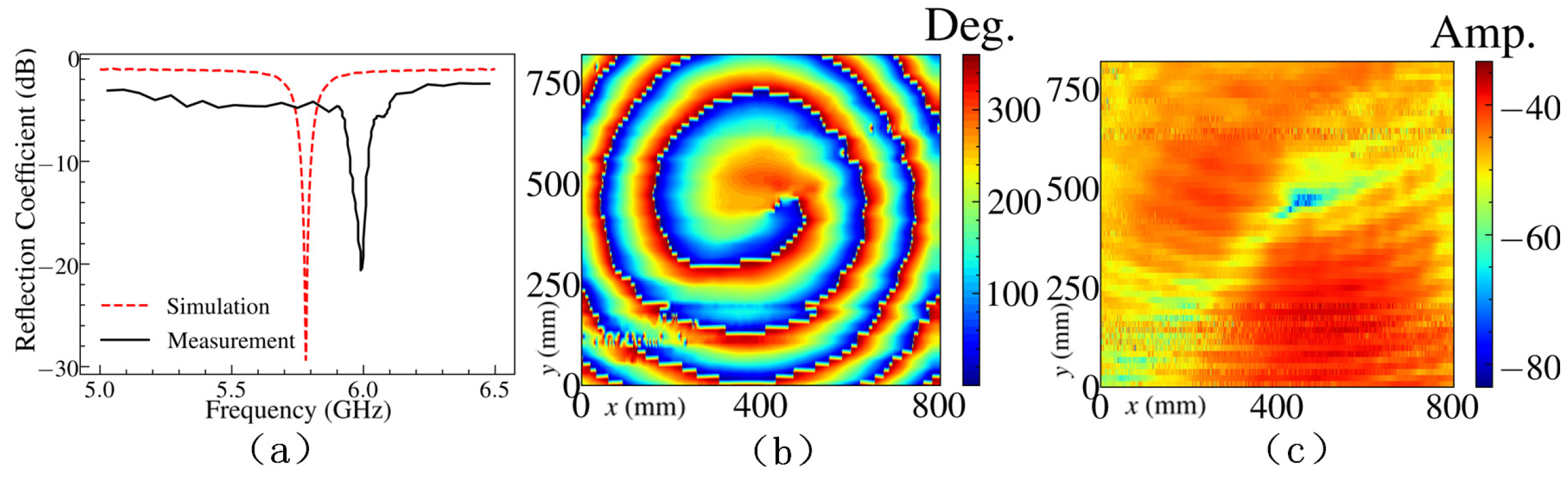
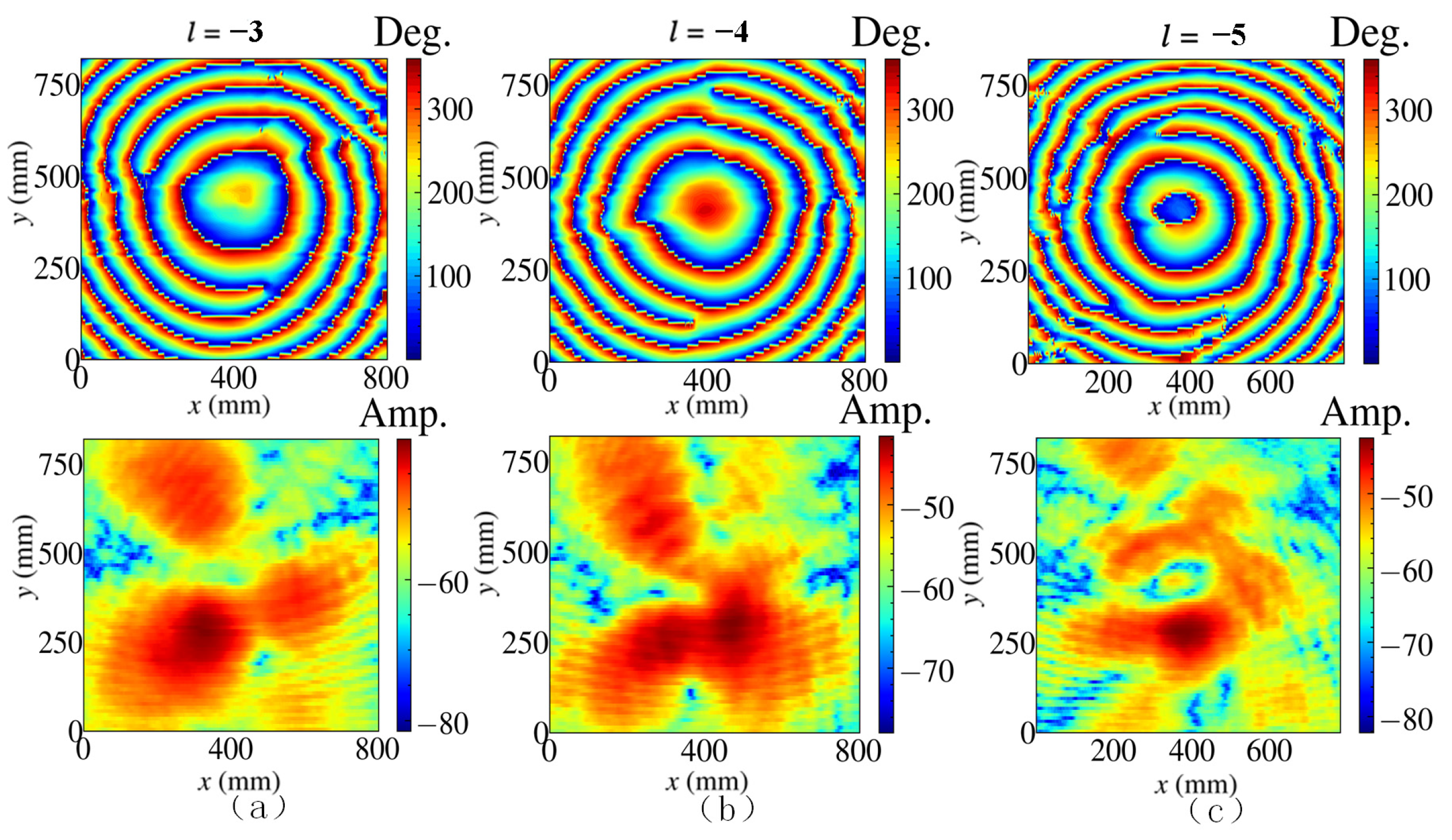
3. Experimental Test Results and Discussion

To validate the design methodology and performance of the array, we fabricated several OAM wave antenna elements and arranged them into an array with prescribed radii, as shown in Figure 10a,b. In order to receive signals from the transmitter, a rectangular patch antenna with the same operating frequency was manufactured as a receiver. The fabricated device is illustrated in Figure 10c. SMA connectors were soldered at the bottom of the fabricated antennas to provide input power signals. A measurement system is also designed to measure the two-dimensional (2D) near-field distribution of the generated OAM beam, as shown in Figure 11, which consists of a vector network analyzer (VNA), a prefabricated OAM wave antenna array, a phase shifter, a power splitter, a 2D guide rail, and a rectangular patch antenna at the receiver.
The feed signal from the VNA is divided into N-way signals through the power divider and then passed through N phase shifters for corresponding phase modulation. The modulated signals are then input to the emitter to generate the corresponding OAM beam. Then, after a certain space transmission, the beam generated by the antenna array is measured by a receiving antenna. Here, a proposed rectangular patch antenna is used as a receiving antenna. The operation frequency is set at 6.00 GHz. The power splitter models purchased are XQY-PS4-2/18-SE and XQY-PS8-2/18-SE, operating frequency range of 2–18 GHZ. In the setup of the measurement system, the near-field scanning range is set to 40 × 40 cm2 (l = −3 and −4) and 45 × 45 cm2 (l = −5) due to the limitation of the length of the guide rail, and the center of the guide rail coincides as much as possible with the optical axial of generated OAM beam. The observation distance between the rectangular patch antenna and the proposed OAM wave antenna array is set to 30 cm. During the operations, phase and amplitude information of near field is scanned and recorded layer-by-layer. Then, all measured results are processed and reproduced.
To facilitate the subsequent analysis of the OAM antenna array, we initially conducted measurements on the reflection coefficient and near-field distribution of a single OAM wave antenna element. Figure 12a presents a comparison between the measured and simulated results. Due to manufacturing errors, environmental factors, contact and connection problems, and other unavoidable reasons, there is a certain degree of error in the measurement results. Nevertheless, we can observe approximate electromagnetic resonances at similar frequencies, and the good impedance matching is reflected by the lowest reflection coefficient below −20 dB. The simulation and measurement results exhibit good consistency.
The near-field (200 mm) phase and amplitude distribution of the OAM wave antenna unit were measured using the aforementioned system without the need for phase shifters and power dividers. The results are shown in Figure 12b,c, respectively, revealing the prominent characteristics of an OAM beam: a vortex phase distribution and a doughnut-shaped amplitude field distribution. A good agreement is observed between the simulated field in Figure 3 and the measured field. This validates that the proposed antenna unit can generate an OAM beam with a mode of −1, confirming the rationality and feasibility of the antenna design.
Moreover, near-field scanning of the amplitude and phase distributions of the high-order arrays composed of OAM antenna elements were carried out. By using the device shown in Figure 11, phase differences of = 120°, 90° and 72° are added to the antenna arrays with N = 3, 4, and 5, respectively. The measured near-field phase distributions of 300 mm near-field mapping distance and amplitude patterns on the observation plane are shown in Figure 13. Compared with the simulation results in Figure 5, it can be observed from the phase map of the 3-antenna arrays in Figure 13a that the same and complete OAM mode with l = −3 is present, while the electric field amplitude map in Figure 13b exhibits a similar distribution to the previous simulation results plotted in Figure 4a (2D electric field amplitude diagram of the 3 antennas array). The measurement results for the arrays composed of 4 and 5 OAM antenna elements (shown in Figure 13) also demonstrate evident spiral phase and intensity distributions of the higher-order OAM modes, consistent with the simulation results and indicative of the characteristics of high-order OAM beams. Minor deformations and misalignments in the measurement results were unavoidable due to processing errors and experimental factors like phase shifters and layer-by-layer scanning. Despite these challenges, we placed significant emphasis on ensuring the accuracy and reliability of these measurements. The phase and amplitude distribution results we obtained consistently demonstrate stability, effectively validating our research. In conclusion, this experiment successfully confirms the OAM antenna array’s capability to generate higher-order modes of OAM beams.
Table 1 is presented to compare the proposed OAM structure with existing ones. As mentioned above, the ring patch antenna capable of generating a complete OAM mode with l = 1 or −1 is the element of the antenna array and a phase gradient of dϕ =2π/N is fed to these elements. Compared to previous works, our designed array can generate high-order OAM electromagnetic waves with a mode number equal to their respective element counts, i.e., a mode number l equal to the number of array elements N. This achieves a breakthrough in the relationship between the number of antenna elements and the number of higher-order modes in the traditional method.

4. Conclusions

A study on an OAM antenna array capable of generating high-order OAM modes based on both the simulation and experiment was presented in this work. Firstly, a ring patch antenna capable of generating a complete OAM mode with l = 1 or −1 was designed, and its excellent performance was experimentally verified. Based on this design, an antenna array was proposed, in which the phase gradient of dϕ =2π/N was fed to the array elements. Numerical simulations conducted on arrays consisting of 3, 4, and 5 elements, based on the phase and amplitude distribution results, demonstrate that each of these arrays can generate high-order OAM electromagnetic waves with a mode number equal to their respective element counts, i.e., a mode number l equal to the number of array elements N. This achievement surpasses the limitation imposed by traditional phased array antennas composed of linear or circular polarized antennas, which can only generate a maximum mode number limited by the relationship: −N/2 < lmax < N/2. Furthermore, a field measurement experimental platform was established to test antenna arrays consisting of 3, 4, and 5 antenna elements. The phase distributions and radiation patterns of these arrays showed a high degree of congruence with the results of numerical simulation and emulation. This alignment substantiates the practical feasibility of the proposed approach. This breakthrough contributes to enhancing the communication capacity and spectral efficiency of electromagnetic waves, which holds significant implications for the future development of wireless communication and radar technology.

Author Contributions

Methodology, S.Z., Z.R. and J.X.; Software, S.G. and J.L.; Validation, J.S., S.G., J.L., S.Z. and Z.R.; Formal analysis, S.G., S.Z. and Z.R.; Investigation, J.S.; Data curation, J.S. and J.L.; Writing—original draft, J.S.; Writing—review and editing, J.X.; Supervision, J.X.; Project administration, J.X.; Funding acquisition, J.X. All authors have read and agreed to the published version of the manuscript.

Funding

This research was funded by National Natural Science Foundation of China under Grant 52102061, 51972033, U2241243, 52372101, Fundamental Research Funds for the Central Universities under Grant 2023ZCJH03, and Teaching Reform Projects at BUPT under Grant 2022CXCY-B03.

Data Availability Statement

The data used in this study are reported in the figures and tables of the paper.

Conflicts of Interest

The authors declare no conflict of interest.

References

  1. Padgett, M.; Allen, L. Light with a twist in its tail. Contemp. Phys. 2010, 41, 275–285. [Google Scholar] [CrossRef]
  2. Wu, G.; Chan, K.F.; Qu, S.; Tong, K.F.; Chan, C.H. Orbital angular momentum (OAM) mode-reconfigurable discrete dielectric lens operating at 300 GHz. IEEE Trans. Terahertz Sci. Technol. 2020, 10, 480–489. [Google Scholar] [CrossRef]
  3. Wang, Z.; Pan, X.; Yang, F.; Xu, S.; Li, M. Real-Time Mode Switching and Beam Scanning of High-Gain OAM Waves Using a 1-Bit Reconfigurable Reflectarray Antenna. Electronics 2020, 9, 2181. [Google Scholar] [CrossRef]
  4. Altynnikov, A.; Platonov, R.; Tumarkin, A.; Petrov, P.K.; Kozyrev, A. Formation of Millimeter Waves with Electrically Tunable Orbital Angular Momentum. Coatings 2021, 11, 569. [Google Scholar] [CrossRef]
  5. Cao, Y.; Yan, S.; Liu, W.; Li, J. Generation of multi-OAM beams using a compact dual-mode source and a 3D-printed Luneburg lens. Opt. Express 2022, 30, 41181–41195. [Google Scholar] [CrossRef]
  6. Mari, E.; Spinello, F.; Oldoni, M.; Ravanelli, R.A.; Romanato, F.; Parisi, G. Near-Field Experimental Verification of Separation of OAM Channels. IEEE Antennas Wirel. Propag. Lett. 2014, 14, 556–558. [Google Scholar] [CrossRef]
  7. Padgett, M.; Bowman, R. Tweezers with a twist. Nat. Photonics 2011, 5, 343–348. [Google Scholar] [CrossRef]
  8. Allen, L.; Beijersbergen, M.W.; Spreeuw, R.; Woerdman, J.P. Orbital angular momentum of light and the transformation of laguerre-gaussian laser modes. Phys. Rev. A 1992, 45, 8185–8189. [Google Scholar] [CrossRef]
  9. Thidé, B.; Then, H.; Sjöholm, J.; Palmer, K.; Bergman, J.; Carozzi, T.D.; Istomin, Y.N.; Ibragimov, N.H.; Khamitova, R. Utilization of photon orbital angular momentum in the low-frequency radio domain. Phys. Rev. Lett. 2007, 99, 087701. [Google Scholar] [CrossRef]
  10. Tennant, A.; Allen, B. Generation of oam radio waves using circular time-switched array antenna. Electron. Lett. 2012, 48, 1365–1366. [Google Scholar] [CrossRef]
  11. Schemmel, P.; Pisano, G.; Maffei, B. Modular spiral phase plate design for orbital angular momentum generation at millimetre wavelengths. Opt. Express 2014, 22, 14712–14726. [Google Scholar] [CrossRef] [PubMed]
  12. Hui, X.; Zheng, S.; Hu, Y.; Xu, C.; Jin, X.; Chi, H.; Zhang, X. Ultralow reflectivity spiral phase plate for generation of millimeter-wave OAM beam. IEEE Antennas Wirel. Propag. Lett. 2015, 14, 966–969. [Google Scholar] [CrossRef]
  13. Naseri, H.; PourMohammadi, P.; Melouki, N.; Ahmed, F.; Iqbal, A.; Denidni, T.A. Generation of Mixed-OAM-Carrying Waves Using Huygens’ Metasurface for Mm-Wave Applications. Sensors 2023, 23, 2590. [Google Scholar] [CrossRef] [PubMed]
  14. Gao, X.L.; Huang, S.; Wei, Y.; Zhai, W.; Xu, W.; Yin, S.; Zhou, J.; Gu, W. An orbital angular momentum radio communication system optimized by intensity controlled masks effectively: Theoretical design and experimental verification. Appl. Phys. Lett. 2014, 105, 241109. [Google Scholar] [CrossRef]
  15. Li, H.; Kang, L.; Wei, F.; Cai, Y.M.; Yin, Y.Z. A Low-Profile Dual-Polarized Microstrip Antenna Array for Dual-Mode OAM Applications. IEEE Antennas Wirel. Propag. Lett. 2017, 16, 3022–3025. [Google Scholar] [CrossRef]
  16. Li, L.; Zhou, X. Mechanically Reconfigurable Single-Arm Spiral Antenna Array for Generation of Broadband Circularly Polarized Orbital Angular Momentum Vortex Waves. Sci. Rep. 2018, 8, 5128. [Google Scholar] [CrossRef]
  17. Jha, P.; Wu, K. Orbital Angular Momentum Wave and Propagation. In Recent Microwave Technologies; IntechOpen: London, UK, 2022. [Google Scholar]
  18. He, Z.X.; Wang, Y.T.; Wang, X.L.; Kupriianov, A.S.; Tuz, V.R.; Fesenko, V.I. Multi-band orbital angular momentum mode-division multiplexing by a compact set of microstrip ring-shaped resonator antenna. Opt. Express 2022, 30, 46209–46226. [Google Scholar] [CrossRef]
  19. Xu, J.C.; Chen, L.; Zhai, X.; Zhang, R.; Mcdonald-Maier, K.D.; Huang, S.; Bi, K. Generation of Continuously Variable-mode Orbital Angular Momentum Beams. Eng. Sci. 2020, 10, 51–57. [Google Scholar] [CrossRef]
  20. Yao, E.; Franke-Arnold, S.; Courtial, J.; Barnett, S.; Padgett, M. Fourier relationship between angular position and optical orbital angular momentum. Opt. Express 2006, 14, 9071–9076. [Google Scholar] [CrossRef]
  21. Roberta, Z.; Barnett, S.M. Quasi-Intrinsic Angular Momentum and the Measurement of Its Spectrum. Phys. Rev. Lett. 2006, 96, 113901. [Google Scholar]
  22. Xu, J.C.; Hao, Y.; Bi, K.; Zhang, R.; Huang, S.; Zhou, J. Microwave Orbital Angular Momentum Beam Generation Based on Circularly Polarized Metasurface Antenna Array. Eng. Sci. 2019, 6, 30–35. [Google Scholar] [CrossRef]
  23. Guo, C.; Zhao, X.; Zhu, C.; Xu, P.; Zhang, Y. An OAM Patch Antenna Design and Its Array for Higher Order OAM Mode Generation. IEEE Antennas Wirel. Propag. Lett. 2019, 18, 816–820. [Google Scholar] [CrossRef]
  24. Wu, Q.W.; Shi, Y.; Li, L. Low-Profile Dual Polarized Multi-Mode OAM Antenna Array. In Proceedings of the 2023 IEEE MTT-S International Wireless Symposium (IWS), Qingdao, China, 14–17 May 2023; pp. 1–3. [Google Scholar]
  25. Sudheep, V.; Srinivas, M.; Kumar, G.K.; Rao, M.V.; Yuvaraj, S.; Kartikeyan, M.V. A Low-Profile UCA Antenna to Generate Conical beam based on OAM Technique for Vehicular Applications. In Proceedings of the 2023 3rd International Conference on Artificial Intelligence and Signal Processing (AISP), Vijayawada, India, 18–20 March 2023; pp. 1–4. [Google Scholar]
  26. Naseri, H.; PourMohammadi, P.; Melouki, N.; Iqbal, A.; Denidni, T.A. A Low-Profile Antenna System for Generating Reconfigurable OAM-Carrying Beams. IEEE Antennas Wirel. Propag. Lett. 2023, 22, 402–406. [Google Scholar] [CrossRef]
  27. Dhanade, Y.B.; Patnaik, A. Multi-mode Orbital Angular Momentum (OAM) Antenna Array. In Proceedings of the 2021 IEEE Indian Conference on Antennas and Propagation (InCAP), Jaipur, India, 13–16 December 2021; pp. 490–493. [Google Scholar]
  28. Veerabathini, S.; Rao, M.V.; Yuvaraj, S.; Kartikeyan, M.V. Generation of a Dual-Mode OAM Beam using a CP UCA Antenna for Wireless Communication. In Proceedings of the 2023 IEEE Wireless Antenna and Microwave Symposium (WAMS), Ahmedabad, India, 7–10 June 2023; pp. 1–4. [Google Scholar]
Figure 1. Schematic diagrams of the ring patch antennas with OAM modes (a) l = −1 and (b) l = 1. Here r is the average radius of the ring patch, c is the patch width of the ring patch, d is the width of the feed line, w is the width of the substrate, h is the length of the substrate, and h1 is the height of the ring patch center.
Electronics 12 04891 g001
Figure 2. (a) Simulated reflection coefficient of the OAM patch antenna. (b) Phase distribution of the generated OAM beam of the antenna with l = −1. (c) Radiation pattern of the antenna with l = −1.
Electronics 12 04891 g002
Figure 3. Structure of the 3-elements antenna arrays composed of OAM antenna with modes (a) l = −1 and (b) l = 1.
Electronics 12 04891 g003
Figure 4. Phase distributions, 2D radiation patterns, and 3D radiation patterns for OAM modes of (a) l = −1, (b) l = −3, and (c) l = 3.
Electronics 12 04891 g004
Figure 5. Structure of the 4-element antenna arrays composed of OAM antenna with modes (a) l = −1 and (b) l = 1.
Electronics 12 04891 g005
Figure 6. Phase distributions, 2D radiation patterns, and 3D radiation patterns for OAM modes of (a) l = −1, (b) l = −4, and (c) l = 4.
Electronics 12 04891 g006
Figure 7. Structure of the 5-element antenna arrays composed of OAM antenna with modes (a) l = −1 and (b) l = 1.
Electronics 12 04891 g007
Figure 8. Phase distributions, 2D radiation patterns, and 3D radiation patterns for OAM modes of (a) l = −1, (b) l = −5, and (c) l = 5.
Electronics 12 04891 g008
Figure 9. Histograms of OAM spectrum weight for OAM mode (a) l = −1, (b) l = −3, (c) l = −4, and (d) l = −5.
Electronics 12 04891 g009
Figure 10. Photographs of the fabricated OAM wave patch antenna (a), the array of four antennas (b), and the rectangular patch antenna (c).
Electronics 12 04891 g010
Figure 11. Measurement system for generating OAM beam. The experimental device layout in the picture has been compressed and adjusted to accommodate the need for shooting. Nevertheless, the depicted connection and measurement method remains authentic and effective.
Electronics 12 04891 g011
Figure 12. Simulated and measured reflection coefficients of the OAM patch antenna with l = −1 (a). Near-field test results of the 2D phase distribution (b) and radiation pattern (c) for the patch antenna operating in OAM mode with l = −1.
Electronics 12 04891 g012
Figure 13. Near-field scanning results of the 2D phase distribution (top) and radiation pattern (bottom) for the arrays of 3 antennas (a), 4 antennas (b), and 5 antennas (c).
Electronics 12 04891 g013
Table 1. Comparison between proposed design and previous works.
Ref.[23][24][25][26][27][28]This work
Freq. (GHz)2.43.655.82.4555.95.8
Number of layers1111121
Number of elements46448162, 3, 4, 5
Mode−2±1, ±2±1±1±1, ±2, ±3±1, ±2±2, ±3, ±4, ±5
Disclaimer/Publisher’s Note: The statements, opinions and data contained in all publications are solely those of the individual author(s) and contributor(s) and not of MDPI and/or the editor(s). MDPI and/or the editor(s) disclaim responsibility for any injury to people or property resulting from any ideas, methods, instructions or products referred to in the content.

