Article

A Lightweight Image Encryption Scheme Using DNA Coding and Chaos

1
Nanoelectronics Integrated Systems Center (NISC), Nile University, Giza 12588, Egypt
2
Engineering Mathematics Department, Faculty of Engineering, Cairo University, Giza 12613, Egypt
*
Author to whom correspondence should be addressed.
Electronics 2023, 12(24), 4895; https://doi.org/10.3390/electronics12244895
Submission received: 19 October 2023 / Revised: 24 November 2023 / Accepted: 25 November 2023 / Published: 5 December 2023
(This article belongs to the Section Circuit and Signal Processing)

Abstract

:
Protecting transmitted multimedia data such as images is a significant concern. This work proposes an encryption algorithm for greyscale images using a Pseudo-Random Number Generator (PRNG), DNA coding, and pixel sum. The proposed approach is implemented on a Genesys 2 FPGA using minimal hardware resources and can operate at a maximum frequency of 110.8 MHz. In addition, several performance evaluation tests are conducted for multiple images, including statistical analysis of the encrypted image, keyspace analysis, and differential attack analysis. The system is compared to recent works with respect to encryption quality and used hardware resources. The proposed scheme outperformed recent chaos-based image encryption schemes.

1. Introduction

The scope of data transmission has broadened in recent years thanks to the rapid development of communications infrastructure such as mobile and internet networks. The public nature of internet networks means that this domain encounters extra difficulties due to unlawful eavesdropping when archiving and sharing multimedia data [1]. Images sent online should be encrypted to prevent snooping eyes from spying on the data. Effectively image encryption should offer high security and minimal complexity to ensure safe data transfer [2].
Deterministic chaos is a prevalent phenomenon observed in continuous-time dynamical systems governed by nonlinear differential equations. Chaotic systems are essential in a wide range of applications, including but not limited to the modelling of robots [3], motion control [4], and random number generation and encryption applications [5]. Chaotic systems have several advantages, such as sensitivity to parameters and initial conditions. Furthermore, the non-periodic nature of chaotic systems makes them ideal candidates for use in encryption systems [6]. Using chaotic cryptography to protect images has been proposed to solve numerous security problems [7]. An encryption image technique utilizing hyperchaotic maps and bit-level Arnold transformation was proposed in [8]. First, this method divides a grayscale image into eight binary images. Then, the images are shifted using a chaotic sequence. Following this, the Arnold transform is used. Lastly, the hyperchaotic map is used to apply image diffusion. Unfortunately, this system necessitates image division, which adds complexity and can prevent image optimization to functional hardware architecture. A true random number generator and a chaotic system were used in [9], which increases the system’s complexity and makes the hardware implementation less feasible. A technique of plaintext-related encryption based on two chaotic systems and DNA manipulation was proposed in [10]. The system relies on particular pixel values in the encryption process. However, this threatens image restoration if any of the selected pixel values are changed. An image encryption algorithm was proposed in [11] using DNA encoding, a hyperchaotic Lorenz system, and Arnold transformation for pixel permutation. The authors proposed a modification when using the Arnold transform in order to avoid its periodicity, which could have represented a weakness for the algorithm. A modified Henon 2D map and a sine map were presented in [12] as a hybrid chaotic technique, where a tent map, logistic map, and sine map were all combined.
The approach presented in [13] for encrypting images used a combination of one-dimensional logistic–tent maps for diffusion and two-dimensional sin–cosine cross-chaotic maps for confusion. Using a complicated wavelet transform, the authors of [14] proposed a 5D hyperchaotic system to encrypt color pictures. Then, a 5D chaotic map was employed to decrypt dispersed sub-bands. In [15], a new 6D hyperchaotic system for visually tunable encryption was presented. A random sequence generator combining three chaotic functions, including the sine chaotic function, was constructed in [16]. A linear congruence generator with the aforementioned random sequences was integrated to construct a resilient substitution matrix, then the resulting matrix was transmitted to a scrambler to augment the stochasticity of the elements. The utilization of discrete quantum steps as a means to create secure cryptographic applications was suggested in [17]. Quantum steps benefit from determinism and high sensitivity to initial conditions. These characteristics create opportunities for a novel approach to quantum hash functions, substitution matrices, and pseudorandom number generators. These components are integral to the implementation of quantum encryption and authentication protocols. In [17], the proposed substitution matrix was derived from a series of random values generated by performing one-dimensional single-particle quantum steps on a circular path. These were then arranged in sequential order, with the indices of their respective positions ultimately constituting the substitution matrix. A four-dimensional multiscroll modified Hopfield neural network (MHNN) utilising sign function polynomials was introduced in [18]. This novel approach was then employed in the field of medical digital watermarking. In [19], the authors developed an innovative memristor incorporating a signed function polynomial memductance. The researchers incorporated it into the Hodgkin–Huxley (HH) model, creating a memristive HH system that can generate multiscroll attractors. They then utilised this system in an image encryption application [19].
In [20], the authors developed an image encryption system with a chaotic block cypher. Their proposed approach employs a chaotic system to encrypt 256 block bits of a plain image. In [21], the authors enhanced the security and key space of the encryption system by integrating chaotic maps and a Linear Feedback Shift Register (LFSR) in a hybrid domain. In [22], the authors developed a system that utilises skew tent mapping and permutation–diffusion techniques to enhance security and expand the key space of the encryption system. In [23], the authors introduced encryption approaches that involve the initial shuffling of the original image using a two-dimensional hyperchaotic discrete system. Subsequently, the Chinese remainder theorem was employed to diffuse and compress the image. In addition, an image encryption system incorporating a circular substitution box and a key stream buffer was introduced in [23]. In [24], the authors employed a methodology that involved dividing the original image into overlapping blocks. They then performed random block shuffling and utilised the Arnold transform and a chaotic map to build a secure matrix for block-wise encryption. In [25], a novel approach to multiple-picture encryption was presented. This technique utilises the Henon map, logistic map, and bit-plane decomposition to convert four grayscale photos into an encrypted PNG image.
Lorenz chaos has been used to encrypt images due to its simplicity. The authors in [26] proposed a symmetric cryptosystem designed explicitly for colour images. Their approach employs a hybrid variant of the Lorenz system to facilitate dispersion while employing DNA sequencing techniques to introduce confusion. The authors of [27] utilised a Lorenz–Rossler chaotic system to conduct pixel diffusion while employing 2D logistic maps for confusion. In [28], the authors proposed an encryption system for RGB images that incorporates Shannon’s confusion and diffusion principles. The proposed strategy was executed using a three-stage process. The initial phase involves using cellular automation to generate the first key. During the second stage, an S-box introduces the necessary elements of nonlinearity and complexity. In the third stage, the second key is generated utilising a solution of the Lorenz system. The simplicity of the Lorenz chaotic system makes it easier to design hardware and reduces its cost.
In [7], the authors proposed a pseudorandom number generator based on the Modified Hopfield Neural Network (MHNN) algorithm. The PRNG was implemented on the Vivado design tool utilising Xilinx XC7Z020CLG400-2 FPGA hardware. The postprocessing unit of the pseudorandom number generator comprised a nonlinear postprocessor and an XOR calculator, with the latter depending on the MHNN chaotic oscillator. The initial dimensional output was utilised as input data to enhance the randomness level in the implemented pseudorandom number generator on the field-programmable gate array (FPGA). In [29], the authors proposed a hardware design for a grayscale image encryption algorithm. The proposed image encryption algorithm utilised pixel-level scrambling, bit-level scrambling, and pixel-value diffusion techniques. This objective was achieved by utilising a field-programmable gate array (FPGA)-based implementation of a chaotic system characterised by line equilibrium. The authors provided the hardware resources used for each of their systems. In [30], an image encryption algorithm was proposed based on a systolic array, and the design aimed for high speed.
Utilizing DNA and Lorenz’s chaotic system allows the hardware resources needed to make a robust image encryption algorithm to be reduced. Lorenz’s chaotic system consists of a few multiplication operations which can be changed to shift operations by making the parameters powers of two. Making parameters constant confines the chaotic system in a state that avoids dynamical degradation [31]. DNA coding and operations can be implemented using simple binary operations. Using both of these methods ensures the minimum hardware resources for image encryption without sacrificing the encryption quality. This paper proposes a DNA-based image encryption system utilizing chaos, DNA and pixel summation, and hardware implementation.
The rest of this paper is organized as follows. Section 2 reviews essential preliminaries of the concepts used in the proposed system. Section 3 describes the encryption and decryption systems. The hardware implementation is presented in Section 4. The results of various types of analysis for the encryption algorithm are discussed in Section 5 along with a comparison of the results to other algorithms. Finally, Section 6 concludes the work.

2. Preliminaries

2.1. Lorenz Chaotic System

The proposed cryptography system requires a source of pseudorandomness that can be generated on the transmitter side and regenerated on the receiver side. In order to realize the chaotic system in the digital domain, the digitization for the chaotic system is accomplished using Euler’s method [32] as shown in Figure 1. The following equations describe the Eulerian solution for the Lorenz chaotic system:
X n + 1 = X n + h σ ( Y n X n ) ,
Y n + 1 = Y n + h ( ρ X n Y n X n Z n ) ,
Z n + 1 = Z n + h ( X n Y n β Z n ) ,
where h is the step size, σ , ρ , and β are the system parameters, and X 0 , Y 0 , and Z 0 are the system variables.

2.2. DNA Coding

The DNA encoding method is used to hide the value of each pixel. In a DNA sequence, there are four possible nucleic acid bases: cytosine (C), thymine (T), adenine (A), and guanine (G); ‘A’ is always complementary to ‘T’ and ‘C’ is always complementary to ‘G’ [33]. Table 1 provides the relationships between the different DNA bases and the equivalent binary code. There are eight suitable coding rules between nucleic acid bases and the binary stream when complementary features of the binary stream are taken into account. Table 1 summarises the rules for DNA encoding and decoding used in the proposed cryptography system.

3. Cryptography Algorithm

3.1. Encryption

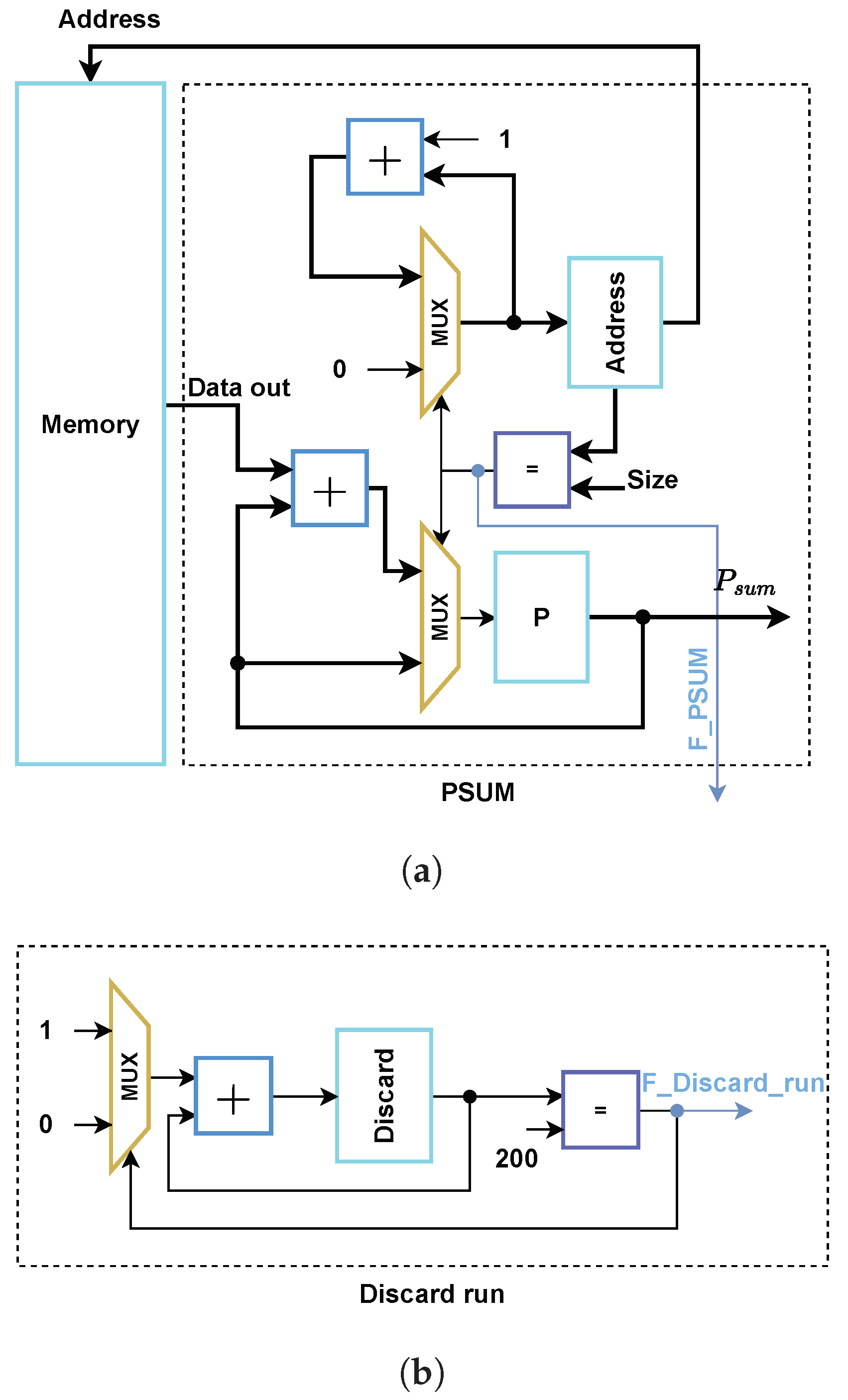
  • Step 1: At the beginning, calculate the summation of all pixels in the image to produce P S u m .
  • Step 2: Calculate P which is equal to m o d ( P S u m , 16 ) .
  • Step 3: Divide the input key into eight keys, each of 32 bits ( K e y 1 . . . K e y 8 ).
  • Step 4: XOR the keys with each other to generate the initial conditions for the chaotic sequence.
  • Step 5: Run the Lorenz chaotic system using the initial conditions from the previous step, then discard the first 200 generated outputs to remove the redundancy.
  • Step 6: Use the chaotic system outputs to generate X b i n 1 , X b i n 2 , X b i n 3 , X b i n 4 , Y b i n 1 , Y b i n 2 , Y b i n 3 , Y b i n 4 such that Y b i n is similar to X b i n and Z b i n .
  • Step 7: The pixel confusion process [34] is accomplished using the value of P. If P is even, then the image is encrypted normally; otherwise, the image is flipped and then encrypted. This is a simple method to change the pixel locations in each iteration.
  • Step 8: Use X b i n 1 , X b i n 2 , X b i n 3 , and X b i n 4 as the DNA encoding rule for every 2 bits of the input image.
  • Step 9: Use Y b i n 1 , Y b i n 2 , Y b i n 3 , and Y b i n 4 as the DNA decoding rule for every 2 bits of the DNA encoded bits generated from the previous step.
  • Step 10: XOR the generated 8-bit output from step 8 with Z b i n and m a s k , where m a s k contains the previous output from step 10 and is initialized with zero. After this, P = P 1 ; return to step 5 and repeat until P = 0 .
The encryption algorithm is further explained in Algorithm 1. Assuming that the input to the algorithm is an image containing L W pixels, then the estimated time complexity is bounded by O ( L W ) .
Algorithm 1 Encryption process
Input: Input image I , and encryption key K
Output: Encrypted image E , and the 16 bit value P
1:
P = m o d ( S U M ( I ) , 16 ) ;
2:
P = P ;
//Divide the key into four 32-bit keys.
3:
{ K e y 1 , . . . , K e y 8 } = K ;
//Set the initial conditions for the chaotic system.
4:
while  P > 0   do
5:
    X 0 = K e y 1 K e y 2 K e y 3 K e y 4 ;
6:
    Y 0 = K e y 3 K e y 4 K e y 5 K e y 6 ;
7:
    Z 0 = K e y 5 K e y 6 K e y 7 K e y 8 ;
8:
   for  i = 1 to (200 + L × W ) do
9:
       X = X 0 + h σ ( Y 0 X 0 ) ;
10:
      Y = Y 0 + h ( ρ X 0 Y 0 X 0 Z 0 ) ;
11:
      Z = Z 0 + h ( X 0 Y 0 β Z 0 ) ;
12:
      X 0 = X ;
13:
      Y 0 = Y ;
14:
      Z 0 = Z ;
15:
     if  i > 200  then
16:
         X b i n 1 = m o d ( f i x ( X × 2 13 ) , 8 ) + 1 ;
17:
         X b i n 2 = m o d ( f i x ( X × 2 16 ) , 8 ) + 1 ;
18:
         X b i n 3 = m o d ( f i x ( X × 2 19 ) , 8 ) + 1 ;
19:
         X b i n 4 = m o d ( f i x ( X × 2 22 ) , 8 ) + 1 ;
20:
         Y b i n 1 = m o d ( f i x ( Y × 2 13 ) , 8 ) + 1 ;
21:
         Y b i n 2 = m o d ( f i x ( Y × 2 16 ) , 8 ) + 1 ;
22:
         Y b i n 3 = m o d ( f i x ( Y × 2 19 ) , 8 ) + 1 ;
23:
         Y b i n 4 = m o d ( f i x ( Y × 2 22 ) , 8 ) + 1 ;
24:
         Z b i n = m o d ( f i x ( Z × 2 22 ) , 8 ) + 1 ;
25:
        if  m o d ( P , 2 ) = = 0  then
26:
           I = I i ;
27:
        else
28:
           I = I ( L × W ) i ;
29:
        end if
30:
         D = D N A e n c o d e ( I , X b i n 1 , X b i n 2 , X b i n 3 , X b i n 4 ) ;
31:
         T = D N A d e c o d e ( D , Y b i n 1 , Y b i n 2 , Y b i n 3 , Y b i n 4 ) ;
32:
         I ( i ) = Z b i n T m a s k ;
33:
         m a s k = I ( i ) ;
34:
         P = P 1
35:
     end if
36:
   end for
37:
    I = I ;
38:
end while
39:
E = I ;
40:
return  E , P

3.2. Decryption

The decryption process is the inverse of the encryption process. The main difference is that P is not calculated; instead, it is sent to the receiver side along with the key.

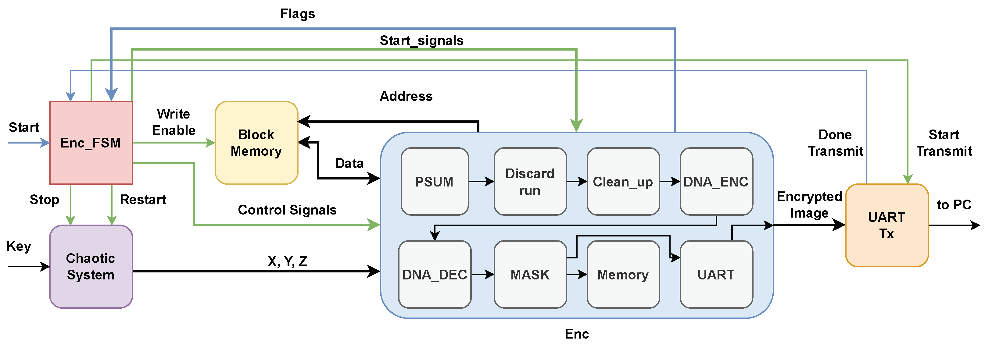
4. Hardware Implementation

Figure 2 shows the hardware implementation for the proposed encryption system. ‘Enc_FSM’ controls all the blocks using the finite state machine (FSM), as shown in Figure 3. The initial conditions of the chaotic system are set using a 256-bit key. To reduce the resources used by the encryption algorithm, σ , ρ , and β from Equation (Section 2.1) are set to 8, 16, and 2, respectively, in order to translate the multiplication operations to simple shift operations, as shown in Figure 4. ‘Block Memory’ contains the 512 × 512 original image. Finally, the ‘Write Enable’ signal controls whether ‘Block Memory’ is written to or read from according to the ‘Address’ and ‘Data’ signals. The ‘Enc’ block contains the operations that the FSM implies. This is accomplished by a series of ‘Start_signals’ and ‘Flags’. After all of the cycles are finished, every 8 bits of the encrypted image are sent over the universal asynchronous receiver/transmitter (UART) to the personal computer (PC).
The FSM, shown in Figure 3, starts in the ‘IDLE’ state. When the ‘START’ signal arrives, the current state changes to ‘PSUM’. In ‘PSUM’, the memory outputs each pixel by incrementing the address to calculate the summation of each pixel in an 8-bit register ‘P’, as shown in Figure 5a. After that, the flag ‘F_PSUM’ is raised and the current state changes to ‘Discard_run’. In ‘Discard_run’, the chaotic system runs for 200 clock cycles to discard them, then the current state changes to ‘Clean_up’. The ‘Discard_run’ block diagram is shown in Figure 5b. After that, a ‘Clean_up’ operation occurs in which all registers are set to zero for two cycles. This allows the system to wait for the block memory to output the desired data, as it has a delay of two clock cycles. After that, DNA encoding and decoding are applied. In the ‘Mask’ state, the mask is calculated and ‘P’ is decremented by one; if it is equal to zero, the next state is ‘UART’, otherwise the next state is ‘Memory’. In the ‘Memory’ state, the generated data are saved in the block memory, then the address is incremented by 1. If it is the last address in the memory, the next state is ‘Discard_run’; otherwise, the next state is ’DNA’. In the ‘UART’ state, the data are transmitted to the PC and the address is incremented by 1.
The encryption system is implemented on Xilinx’s Genesys 2 FPGA using Verilog hardware description language (HDL). The proposed system can run at a maximum frequency of 110.8 MHz with a throughput of 147.73 Mbps. Table 2 shows the resource utilization of the encryption system, where the resource utilization percentages for the LUTs, FFs, and DSPs are less than 1%. Table 3 compares the hardware resources used in the proposed system to other works. The simplicity of the system and its use of pixel summuation, DNA, and Lorenz chaos reduces the LUTs required for a secure image encryption algorithm. The proposed algoritm uses more Block RAM, as it aims to encrypt 512 × 512 images, while in [30] the system encrypted 300 × 300 images. The system requires a low amount of resources, making it suitable for low-cost hardware devices.

5. Results and Discussion

The proposed system was tested using the grayscale ‘Lena’ ( 256 × 256 ) , ‘Pepper’ ( 512 × 512 ) , and ‘Baboon’ ( 512 × 512 ) images. Figure 6 shows the original Baboon image and the same image after encryption using our proposed algorithm.

5.1. Statistical Analysis

5.1.1. Histogram

The histogram of the image represents the distribution of pixel values. A safe encryption technique should produce an encrypted image with a histogram that is nearly uniform in distribution. Figure 7 shows the histograms of the original and encrypted image using the proposed encryption scheme for the Lena, Baboon, and Pepper images. The histograms show the uniform distribution of the pixels for the encrypted images.

5.1.2. Peak Signal-to-Noise Ratio and Mean Square Error

To test the encryption quality, we measured the Peak Signal-to-Noise Ratio ( P S N R ) and the Mean Square Error ( M S E ), which are calculated as follows:
M S E = 1 L W i = 1 L j = 1 W O i , j E i , j 2 ,
P S N R = 10 log 10 ( 2 n 1 ) 2 M S E ,
where O i , j and E i , j represent the original and encrypted images at location ( i , j ) , respectively, and n represents the number of bits per pixel. High M S E and low P S N R indicate a significant difference between the encrypted image and the original.

5.1.3. Correlation

The proximity between two neighbouring pixels in an image can be measured via correlation analysis. The neighbouring pixels in the original image are highly correlated across the diagonal, vertical, and horizontal axes. An ideal image encryption technique should lessen the degree to which neighbouring pixels are correlated with each other [35]. The following equations were used to calculate the correlation coefficients:
ρ = C o v ( x , y ) D ( x ) D ( y ) ,
C o v ( x , y ) = 1 L W i = 1 L W x i 1 L W i = 1 L W x i y i 1 L W i = 1 L W y i ,
D ( x ) = 1 L W i = 1 L W x i 1 L W i = 1 L W x i 2 ,
D ( y ) = 1 L W i = 1 L W y i 1 L W i = 1 L W y i 2 ,
where C o v ( x , y ) represents the covariance between pixels x and y, D represents the standard deviation, and L W represents the number of pixels in the image. The correlation for the Baboon image is shown in Figure 8, and the results are provided in Table 4, where the values are almost zero in the vertical, horizontal, and diagonal directions. This means that the pixels are uncorrelated, which is a desirable property in image encryption.

5.1.4. Information Entropy

The information entropy is the average amount of information represented by each pixel [35]. It is calculated as follows:
E n t r o p y = i = 0 255 P ( i ) l o g 2 P ( i ) ,
where P ( i ) represents the probability of i. The possible values for a pixel in a grayscale image are 2 8 ; hence, 8 bits is the ideal entropy value, indicating that the information is evenly dispersed across all pixel values. Table 4 indicates that the encrypted image’s entropy approaches eight.

5.2. Differential Attack

To evaluate the efficacy of resistance to differential attacks, the Number of Pixel Change Rate ( N P C R ) and Unified Average Changing Intensity ( U A C I ) tests were used [35]. These two tests explain the sensitivity of the encrypted image to minor modifications of the original image. The equations used to calculate the N P C R and U A C I are as follows:
N P C R = 1 L W i = 1 L j = 1 W D E ( i , j ) × 100 % ,
U A C I = 1 L W i = 1 L j = 1 W E 1 ( i , j ) E 2 ( i , j ) 255 × 100 % ,
D E ( i , j ) = 0 , if E 1 ( i , j ) = E 2 ( i , j ) , 1 , if E 1 ( i , j ) E 2 ( i , j ) ,
where E 1 and E 2 represent the two images resulting from encrypting the original image and the original with minor modifications, L and W are the dimensions of the image, and D E ( i , j ) represents the difference between the corresponding pixels in the encrypted copies of the original and updated images. Table 4 provides the U A C I and N P C R values, which were calculated from the mean of 50 iterations. All of the U A C I and N P C R values are near the optimum respective values of 33.46% and 99.61% [6]. Hence, the encryption method is sensitive to minor modifications to the pixels in the original image.

5.3. Known Plain-Text Attack

An adversary might attempt to use an entirely black or white image to find plausible patterns in a cryptographic model [36]. The proposed system can be used to apply a cipher to the black and white images. The ciphered images are illustrated in Figure 9, showing no visible patterns. The entropy values for the encrypted images are the same as other encrypted images, and the encrypted images’ correlation coefficients are near zero. The results shown in Table 5 demonstrate that the proposed system is effective against such attacks.

5.4. The Key Space

The keyspace of an encryption algorithm must be very vast in order to withstand brute-force attacks. Therefore, the proposed approach has 2 256 different keys, allowing it to resist this type of attack [35].

5.5. NIST SP-800-22 Test

The NIST 800-22 is a compilation of statistical tests designed to evaluate the efficacy of pseudorandom number generators (PRNGs), random number generators (RNGs), and random sequences. This test suite consists of a total of fifteen statistical tests. The determination of whether a sequence can be accepted as a random sequence is made based on the P-value generated after each test [37]. The NIST test was successfully applied using the encrypted Lena image, with the results presented in Table 6.

6. Conclusions

The encryption algorithm employed in this paper is based on a Lorenz chaotic system and DNA manipulation. The encryption iterations are based on calculating the pixel summation for the whole image. This increases the encryption algorithm’s dependence on each bit of the input image, which protects the system against differential attacks. Our performance evaluations demonstrated the reliability and effectiveness of the proposed system. In addition, the design was implemented on FPGA, employing low hardware resources at a maximum frequency of 110.8 MHz, making it suitable for real-world application hardware implementations.

Author Contributions

Conceptualization, M.A.F., W.S.S. and L.A.S.; software, M.A.F.; formal analysis, M.A.F. and W.S.S.; investigation, M.A.F. and W.S.S.; writing—original draft preparation, M.A.F.; writing—review and editing, W.S.S. and L.A.S.; supervision, W.S.S. and L.A.S.; project administration, L.A.S.; funding acquisition, L.A.S. All authors have read and agreed to the published version of the manuscript.

Funding

This paper is based upon work supported by the Science, Technology, and Innovation Funding Authority (STIFA) under grant number (#38161).

Data Availability Statement

Data are contained within the article.

Conflicts of Interest

None of the authors have any conflicts of interest to disclose.

References

  1. Lai, Q.; Hu, G.; Erkan, U.; Toktas, A. A novel pixel-split image encryption scheme based on 2D Salomon map. Expert Syst. Appl. 2023, 213, 118845. [Google Scholar] [CrossRef]
  2. FPGA Hardware Co-Simulation of Image Encryption Using Stream Cipher Based on Chaotic Maps. Sens. Imaging 2020, 21, 35. [CrossRef]
  3. ElSafty, A.H.; Tolba, M.F.; Said, L.A.; Madian, A.H.; Radwan, A.G. A study of the nonlinear dynamics of human behavior and its digital hardware implementation. J. Adv. Res. 2020, 25, 111–123. [Google Scholar] [CrossRef] [PubMed]
  4. Gohari, P.S.; Mohammadi, H.; Taghvaei, S. Using chaotic maps for 3D boundary surveillance by quadrotor robot. Appl. Soft Comput. 2019, 76, 68–77. [Google Scholar] [CrossRef]
  5. Elsafty, A.H.; Tolba, M.F.; Said, L.A.; Madian, A.H.; Radwan, A.G. Enhanced hardware implementation of a mixed-order nonlinear chaotic system and speech encryption application. AEU-Int. J. Electron. Commun. 2020, 125, 153347. [Google Scholar] [CrossRef]
  6. Mohamed, S.M.; Sayed, W.S.; Madian, A.H.; Radwan, A.G.; Said, L.A. An Encryption Application and FPGA Realization of a Fractional Memristive Chaotic System. Electronics 2023, 12, 1219. [Google Scholar] [CrossRef]
  7. Yu, F.; Zhang, Z.; Shen, H.; Huang, Y.; Cai, S.; Du, S. FPGA implementation and image encryption application of a new PRNG based on a memristive Hopfield neural network with a special activation gradient. Chin. Phys. B 2022, 31, 020505. [Google Scholar] [CrossRef]
  8. Ni, Z.; Kang, X.; Wang, L. A novel image encryption algorithm based on bit-level improved Arnold transform and hyper chaotic map. In Proceedings of the 2016 IEEE International Conference on Signal and Image Processing (ICSIP), Beijing, China, 13–15 August 2016; pp. 156–160. [Google Scholar]
  9. Zhou, S.; Wang, X.; Zhang, Y.; Ge, B.; Wang, M.; Gao, S. A novel image encryption cryptosystem based on true random numbers and chaotic systems. Multimed. Syst. 2022, 28, 95–112. [Google Scholar] [CrossRef]
  10. Li, M.; Wang, M.; Fan, H.; An, K.; Liu, G. A novel plaintext-related chaotic image encryption scheme with no additional plaintext information. Chaos Solitons Fractals 2022, 158, 111989. [Google Scholar] [CrossRef]
  11. Fetteha, M.A.; Sayed, W.S.; Said, L.A.; Radwan, A.G. Chaos-Based Image Encryption Using DNA Manipulation and a Modified Arnold Transform. In Proceedings of the Model and Data Engineering: 11th International Conference, MEDI 2022, Cairo, Egypt, 21–24 November 2022; Springer: Berlin/Heidelberg, Germany, 2022; pp. 3–15. [Google Scholar]
  12. Sheela, S.; Suresh, K.; Tandur, D. Image encryption based on modified Henon map using hybrid chaotic shift transform. Multimed. Tools Appl. 2018, 77, 25223–25251. [Google Scholar] [CrossRef]
  13. Khalil, N.; Sarhan, A.; Alshewimy, M.A. An efficient color/grayscale image encryption scheme based on hybrid chaotic maps. Opt. Laser Technol. 2021, 143, 107326. [Google Scholar] [CrossRef]
  14. Kaur, M.; Singh, D.; Sun, K.; Rawat, U. Color image encryption using non-dominated sorting genetic algorithm with local chaotic search based 5D chaotic map. Future Gener. Comput. Syst. 2020, 107, 333–350. [Google Scholar] [CrossRef]
  15. Wang, X.; Ren, Q.; Jiang, D. An adjustable visual image cryptosystem based on 6D hyperchaotic system and compressive sensing. Nonlinear Dyn. 2021, 104, 4543–4567. [Google Scholar] [CrossRef]
  16. Yi, L.; Tong, X.; Wang, Z.; Zhang, M.; Zhu, H.; Liu, J. A novel block encryption algorithm based on chaotic S-box for wireless sensor network. IEEE Access 2019, 7, 53079–53090. [Google Scholar] [CrossRef]
  17. Abd El-Latif, A.A.; Abd-El-Atty, B.; Mazurczyk, W.; Fung, C.; Venegas-Andraca, S.E. Secure data encryption based on quantum walks for 5G Internet of Things scenario. IEEE Trans. Netw. Serv. Manag. 2020, 17, 118–131. [Google Scholar] [CrossRef]
  18. Yu, F.; Chen, H.; Kong, X.; Yu, Q.; Cai, S.; Huang, Y.; Du, S. Dynamic analysis and application in medical digital image watermarking of a new multi-scroll neural network with quartic nonlinear memristor. Eur. Phys. J. Plus 2022, 137, 434. [Google Scholar] [CrossRef] [PubMed]
  19. Zhang, S.; Zheng, J.; Wang, X.; Zeng, Z. Multi-scroll hidden attractor in memristive HR neuron model under electromagnetic radiation and its applications. Chaos Interdiscip. J. Nonlinear Sci. 2021, 31, 011101. [Google Scholar] [CrossRef] [PubMed]
  20. Amin, M.; Faragallah, O.S.; Abd El-Latif, A.A. A chaotic block cipher algorithm for image cryptosystems. Commun. Nonlinear Sci. Numer. Simul. 2010, 15, 3484–3497. [Google Scholar] [CrossRef]
  21. Abd El-Latif, A.A.; Niu, X.; Amin, M. A new image cipher in time and frequency domains. Opt. Commun. 2012, 285, 4241–4251. [Google Scholar] [CrossRef]
  22. Zhang, G.; Liu, Q. A novel image encryption method based on total shuffling scheme. Opt. Commun. 2011, 284, 2775–2780. [Google Scholar] [CrossRef]
  23. Zhu, H.; Zhao, C.; Zhang, X. A novel image encryption–compression scheme using hyper-chaos and Chinese remainder theorem. Signal Process. Image Commun. 2013, 28, 670–680. [Google Scholar] [CrossRef]
  24. Tang, Z.; Zhang, X.; Lan, W. Efficient image encryption with block shuffling and chaotic map. Multimed. Tools Appl. 2015, 74, 5429–5448. [Google Scholar] [CrossRef]
  25. Tang, Z.; Song, J.; Zhang, X.; Sun, R. Multiple-image encryption with bit-plane decomposition and chaotic maps. Opt. Lasers Eng. 2016, 80, 1–11. [Google Scholar] [CrossRef]
  26. ElKamchouchi, D.H.; Mohamed, H.G.; Moussa, K.H. A bijective image encryption system based on hybrid chaotic map diffusion and DNA confusion. Entropy 2020, 22, 180. [Google Scholar] [CrossRef] [PubMed]
  27. Kumar, V.; Girdhar, A. A 2D logistic map and Lorenz-Rossler chaotic system based RGB image encryption approach. Multimed. Tools Appl. 2021, 80, 3749–3773. [Google Scholar] [CrossRef]
  28. Alexan, W.; ElBeltagy, M.; Aboshousha, A. Rgb image encryption through cellular automata, s-box and the lorenz system. Symmetry 2022, 14, 443. [Google Scholar] [CrossRef]
  29. Sambas, A.; Vaidyanathan, S.; Zhang, X.; Koyuncu, I.; Bonny, T.; Tuna, M.; Alçin, M.; Zhang, S.; Sulaiman, I.M.; Awwal, A.M.; et al. A novel 3D chaotic system with line equilibrium: Multistability, integral sliding mode control, electronic circuit, FPGA implementation and its image encryption. IEEE Access 2022, 10, 68057–68074. [Google Scholar] [CrossRef]
  30. Ciylan, F.; Ciylan, B.; Atak, M. FPGA-Based Chaotic Image Encryption Using Systolic Arrays. Electronics 2023, 12, 2729. [Google Scholar] [CrossRef]
  31. Lu, X.; Xie, E.Y.; Li, C. Periodicity Analysis of the Logistic Map Over Ring Z3n. Int. J. Bifurc. Chaos 2023, 33, 2350063. [Google Scholar] [CrossRef]
  32. Sayed, W.S.; Mohamed, S.M.; Elwakil, A.S.; Said, L.A.; Radwan, A.G. Numerical sensitivity analysis and hardware verification of a transiently-chaotic attractor. Int. J. Bifurc. Chaos 2022, 32, 2250103. [Google Scholar] [CrossRef]
  33. Chen, L.; Li, C.; Li, C. Security measurement of a medical communication scheme based on chaos and DNA coding. J. Vis. Commun. Image Represent. 2022, 83, 103424. [Google Scholar] [CrossRef]
  34. Winarno, E.; Nugroho, K.; Adi, P.W. Combined Interleaved Pattern to Improve Confusion-Diffusion Image Encryption based on Hyperchaotic System. IEEE Access 2023, 11, 69005–69021. [Google Scholar] [CrossRef]
  35. Wu, X.; Zhu, B.; Hu, Y.; Ran, Y. A novel color image encryption scheme using rectangular transform-enhanced chaotic tent maps. IEEE Access 2017, 5, 6429–6436. [Google Scholar]
  36. Tuli, R.; Soneji, H.; Vahora, S.; Churi, P.; Bangalore, N.M. PixJS: A novel chaos-based approach for image encryption. Concurr. Comput. Pract. Exp. 2022, 34, e6990. [Google Scholar] [CrossRef]
  37. Rukhin, A.; Soto, J.; Nechvatal, J.; Smid, M.; Barker, E. A Statistical Test Suite for Random and Pseudorandom Number Generators for Cryptographic Applications; US Department of Commerce, Technology Administration, National Institute of Standards and Technology; Technical Report; Booz-Allen and Hamilton Inc.: Mclean, VA, USA, 2001. [Google Scholar]
Figure 1. Lorenz chaotic system simulation results, where the step size is h = 2 7 , the system parameters are σ = 8 , ρ = 16 , β = 2 , and the initial values of the system variables are X 0 = Y 0 = Z 0 = 10 .
Electronics 12 04895 g001
Figure 2. Hardware block diagram of the encryption process.
Electronics 12 04895 g002
Figure 3. Finite state machine for the implemented hardware design for the encryption process.
Electronics 12 04895 g003
Figure 4. Hardware block diagram of the Lorenz chaotic system.
Electronics 12 04895 g004
Figure 5. Hardware block diagram for (a) ‘PSUM’ and (b) ‘Discard Run’ blocks.
Electronics 12 04895 g005
Figure 6. Baboon: (a) original and (b) encrypted images.
Electronics 12 04895 g006
Figure 7. Original (left) and encrypted image histograms (right) for (a) Lena, (b) Baboon, and (c) Pepper.
Electronics 12 04895 g007
Figure 8. The correlation for the original (left) and encrypted (right) Baboon images in the (a) horizontal, (b) vertical, and (c) diagonal directions.
Electronics 12 04895 g008aElectronics 12 04895 g008b
Figure 9. Encrypted images for (a) all black image and (b) all white image.
Electronics 12 04895 g009
Table 1. DNA binary codes and their respective encoding and decoding rules.
DNA BaseBinary Code Rules
87654321
C11CAGTGCTAC
T10TCTCAAGGT
A01AGAGTTCCA
G00GTCACGATG
Table 2. Encryption system hardware resource utilization.
ResourcesUtilizationUtilization%
Lookup Tables (LUTs)5300.26
Flip Flops (FFs)2910.07
Block RAMs (BRAMs)6414.38
Digital Signal Processors (DSPs)80.95
Table 3. Encryption system hardware resource comparison.
ResourcesThis Paper[7][29][30]
Lookup Tables (LUTs)53042,125768138,273
Flip Flops (FFs)29152,05084792371
Block RAMs (Mb)2.25--1.12
Digital Signal Processors (DSPs)8--63
Operating Frequency (MHz)110.8109.337462.731573
Best value in each category is in bold.
Table 4. Performance analysis.
ReferenceEncrypted
Image
Encryption
Quality Metrics
Correlation (× 102)EntropyThe Robustness against
The Differential Attacks
MSEPSNRHVDNPCR (%)UACI (%)
This paperLena77949.2127 1.10-1.12−0.497.997299.646633.4061
Baboon72449.5305−0.04−0.09 0.007.999899.591133.4432
Pepper84038.8862−0.18 0.11−0.157.999399.607133.4254
[11]Lena78289.1943 0.42 0.12 0.017.997399.604233.4204
Baboon72899.5041−0.18−0.07−0.017.999399.609133.4791
Pepper83908.8931 0.17−0.08 0.397.999199.608633.4612
[10]Lena77939.21−0.18 0.11−0.097.997599.614733.4723
Baboon72859.52 0.19−0.41−0.997.999299.606333.4565
Pepper84368.86−0.63−0.06−0.467.999399.611233.4776
[9]Lena9.2645−0.03−0.07−0.017.997799.6033.45
[8]Lena−0.06−0.39 0.167.9978
Baboon−0.23−0.00−0.157.998299.605633.4282
[29]Lena−0.28-3.18−0.437.9976
Baboon−0.44−0.97 1.287.9972
Pepper−0.45 0.59 0.017.9971
[30]Lena−0.69 1.51−0.067.997799.6024.62
Pepper−0.29−0.89−0.737.997599.6325.44
Best value in each category for each image is in bold.
Table 5. Entropy and correlation for encrypted black and white images.
ImageEntropyCorrelation ( × 10 2 )
HVD
Black0---
Black encrypted7.9993−0.07−0.06 0.02
White0---
White encrypted7.9994−0.07 0.06−0.02
Table 6. Lena NIST test results.
Testp-ValueResultPROP.Result
BlockFrequency0.8343081.000
Serial0.0301841.000
FFT0.0251931.000
Frequency0.0002961.000
Runs0.0487161.000
RandomExcursions0.1913940.992
LongestRun0.0487161.000
Rank0.4372741.000
Universal0.3504851.000
CumulativeSums0.5923971.000
OverlappingTemplate0.1626061.000
NonOverlappingTemplate0.3584520.991
RandomExcursionsVariant0.1208781.000
ApproximateEntropy0.1626061.000
LinearComplexity0.739918 1.000
Disclaimer/Publisher’s Note: The statements, opinions and data contained in all publications are solely those of the individual author(s) and contributor(s) and not of MDPI and/or the editor(s). MDPI and/or the editor(s) disclaim responsibility for any injury to people or property resulting from any ideas, methods, instructions or products referred to in the content.

