
A Wireless Electrooculogram (EOG) Wearable Using Conductive Fiber Electrode

Abstract
:1. Introduction
2. Electrospun Conductive Biopotential Electrode with Porous Fiber
2.1. Overview of Conductive Biopotential Electrodes
2.2. Fabricating Process of Semi-Dry Electrode with Porous Fiber
2.3. Impedance Analysis of Semi-Dry Electrode
3. EOG Experimental Setup and Results
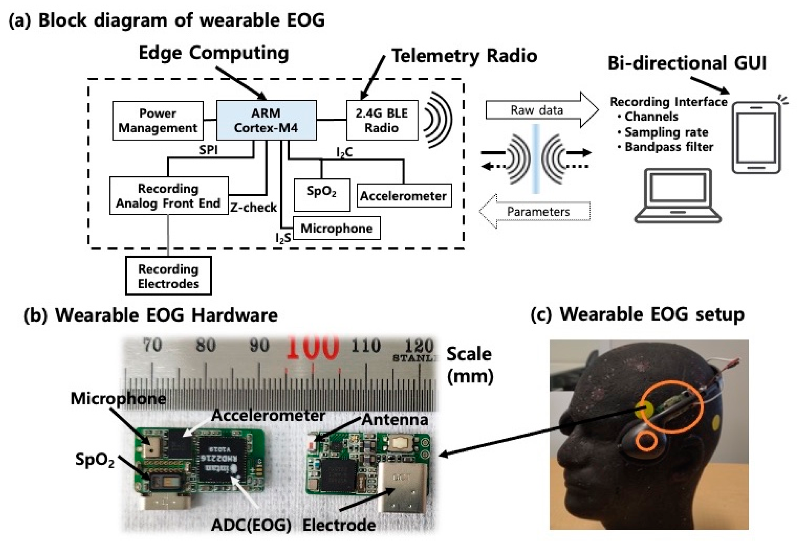
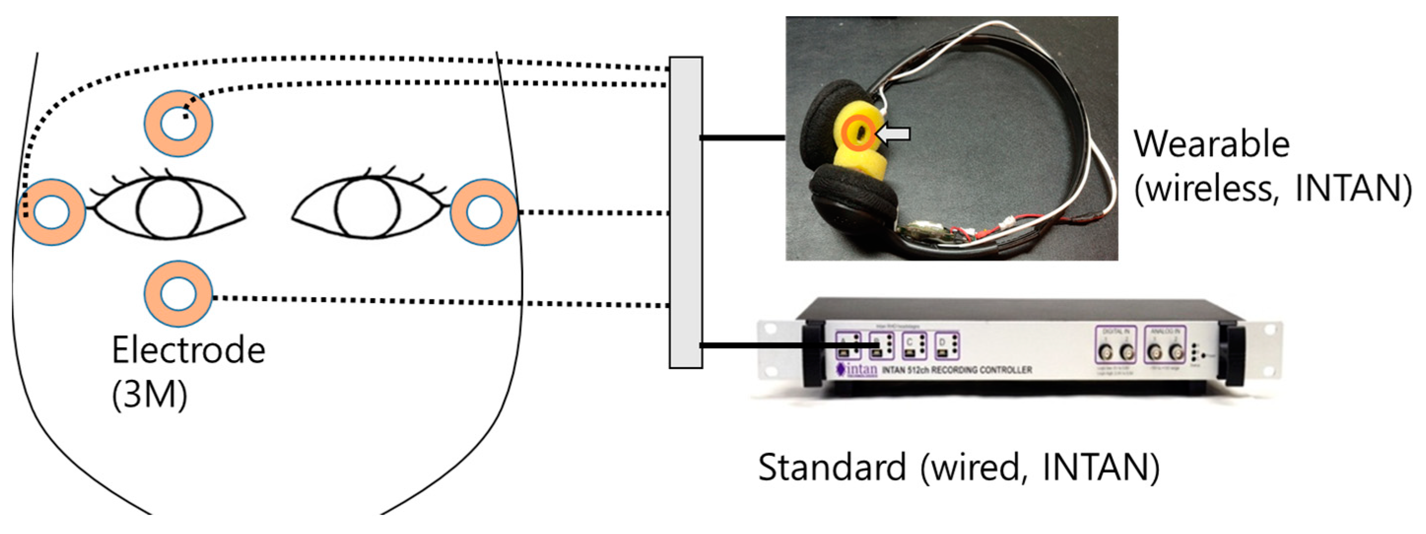
3.1. Wireless EOG Device for Wearable Applications
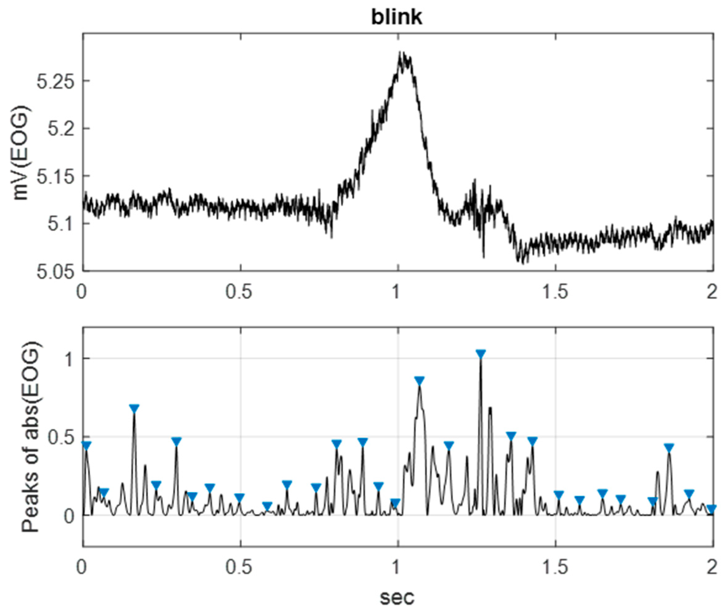
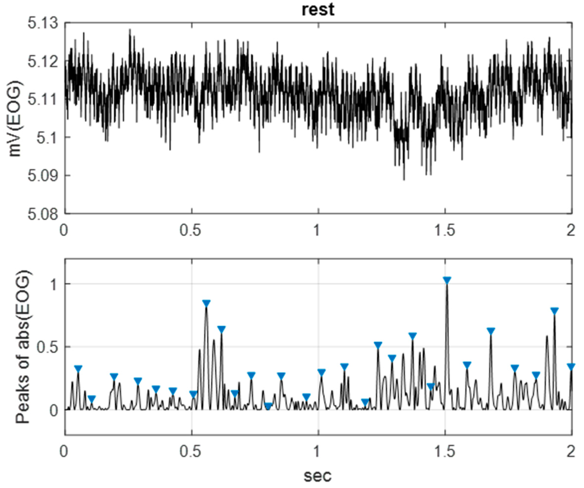
3.2. Single Eye Movements Discrimination
4. Conclusions
Author Contributions
Funding
Institutional Review Board Statement
Informed Consent Statement
Data Availability Statement
Acknowledgments
Conflicts of Interest
Appendix A

| Scheme | Details | Advantage | Disadvantage |
|---|---|---|---|
| VOG (Video-oculography) | Detect capturing eye motion | Direct eye tracking | Varying light conditions Droopy eyelids, Heavy image processing |
| VOG (Video based IR) | Capturing black area of the pupil by illuminating IR | Direct eye tracking Robust to light environment | Droopy eyelids, Heavy power consumption Hard to wear (heavy equipment) |
| EOG (Dry electrode) | Bio potential measurement | Wearable (by wireless) Low power consumption Robust to light environment | High contact impedance (weak to noise) |
| EOG (Wet electrode) | Bio potential measurement | Wearable (by wireless) Low power consumption Low contact impedance | Short time recording Uncomfortable using gel |
| EOG (Semi-dry electrode) | Bio potential measurement | Wearable (by wireless) Low power consumption Low contact impedance Long time recording | Indirect eye tracking |
References
- NHTSA. Driving. (United States Department of Transportation). Retrieved 2022. 2022. Available online: https://www.nhtsa.gov/risky-driving/drowsy-driving (accessed on 31 August 2022).
- Meng, Q.; Tan, X.; Jiang, C.; Xiong, Y.; Yan, B.; Zhang, J. Tracking Eye Movements During Sleep in Mice. Front. Neurosci. 2021, 15, 616760. [Google Scholar] [CrossRef] [PubMed]
- Rahman, M.M.; Bhuiyan, M.I.H.; Hassan, A.R. Sleep stage classification using single-channel EOG. Comput. Biol. Med. 2018, 1, 211–220. [Google Scholar] [CrossRef] [PubMed]
- Land, M.F.; Hayhoe, M. In what ways do eye movements contribute to everyday activities? Vis. Res. 2001, 41, 3559–3565, Retrieved 20 September 2022. Available online: https://www.bankrate.com/insurance/car/drowsy-driving-statistics/ (accessed on 31 August 2022). [CrossRef] [PubMed] [Green Version]
- Jia, Y.; Tyler, C.W. Measurement of saccadic eye movements by electrooculography for simultaneous EEG recording. Behav. Res. Methods 2019, 51, 2139–2151. [Google Scholar] [CrossRef] [PubMed] [Green Version]
- Dzedzickis, A.; Kaklauskas, A.; Bucinskas, V. Human Emotion Recognition: Review of Sensors and Methods. Sensors 2020, 20, 592. [Google Scholar] [CrossRef] [PubMed] [Green Version]
- Luo, W.; Cao, J.; Ishikawa, K.; Ju, D. A Human-Computer Control System Based on Intelligent Recognition of Eye Movements and Its Application in Wheelchair Driving. Multimodal Technol. Interact. 2021, 5, 50. [Google Scholar] [CrossRef]
- Levo, H.; Aalto, H.; Hirvonen, T.P. Nystagmus measured with video-oculography: Methodological aspects and normative data. ORL 2004, 66, 101–104. [Google Scholar] [CrossRef] [PubMed]
- Creel, D.J. The electrooculogram. Handb. Clin. Neurol. 2019, 160, 495–499. [Google Scholar] [PubMed]
- Martinez-Marquez, D.; Pingali, S.; Panuwatwanich, K.; Stewart, R.A.; Mohamed, S. Application of Eye Tracking Technology in Aviation, Maritime, and Construction Industries: A Systematic Review. Sensors 2021, 21, 4289. [Google Scholar] [CrossRef] [PubMed]
- Yazicioglu, R.F.; Van Hoof, C.; Puers, R. Biopotential Readout Circuits for Portable Acquisition Systems; Springer: Dordrech, The Netherlands, 2008. [Google Scholar]
- Faisal, S.N.; Amjadipour, M.; Izzo, K.; Singer, J.A.; Bendavid, A.; Lin, C.-T.; Iacopi, F. Non-invasive on-skin sensors for brain machine interfaces with epitaxial graphene. J. Neural Eng. 2021, 18, 066035. [Google Scholar] [CrossRef] [PubMed]
- Li, G.-L.; Wu, J.-T.; Xia, Y.-H.; He, Q.-G.; Jin, H.-G. Review of semi-dry electrodes for EEG recording. J. Neural Eng. 2020, 17, 051004. [Google Scholar] [CrossRef] [PubMed]
- Liu, J.; Lin, S.; Li, W.; Zhao, Y.; Liu, D.; He, Z.; Wang, D.; Lei, M.; Hong, B.; Wu, H. Ten-Hour Stable Noninvasive Brain-Computer Interface Realized by Semidry Hydrogel-Based Electrodes. Research 2022, 2022, 9830457. [Google Scholar] [CrossRef] [PubMed]
- Huang, Z.; Zhou, Z.; Zeng, J.; Lin, S.; Wu, H. Flexible electrodes for non-invasive brain–computer interfaces: A perspective. APL Mater. 2022, 10, 090901. [Google Scholar] [CrossRef]
- de la Fuente, J. Properties of Graphene. Retrieved 29 August 2019. 2022. Available online: https://www.graphenea.com/pages/graphene-properties#.XIs2Bi2ZOu4 (accessed on 31 August 2022).
- Nixor. The World of Graphene—Nixor. Retrieved 29 August 2019. 2022. Available online: https://www.nixor.co.uk/the-world-of-graphene/ (accessed on 31 August 2022).
- Park, J.S. Electrospinning and its Applications. Adv. Nat. Sci. Nanosci. Nanotechnol. 2010, 1, 043002. [Google Scholar] [CrossRef] [Green Version]
- Li, Z.; Yuan, Y.; Chen, B.; Liu, Y.; Nie, J.; Ma, G. Photo and Thermal Cured Silicon-Containing Diethynylbenzene Fibers via Melt Electrospinning with Enhanced Thermal Stability. J. Polym. Sci. Part A Polym. Chem. 2017, 55, 2815–2823. [Google Scholar] [CrossRef]
- Braiek, M.; Sapountzi, E.; Chateaux, J.F.; Vocanson, F.; Lagarde, F.; Maaref, A.; Jaffrezic-Renault, N. Impedimetric Biosensor Based on Electrospun PEI/PVA Decorated with Gold Nanoparticles for Glucose Detection. J. Electrochem. Soc. 2015, 162, B275–B281. [Google Scholar]
- Faisal, S.N.; Iacopi, F. Thin-Film Electrodes Based on Two-Dimensional Nanomaterials for Neural Interfaces. ACS Appl. Nano Mater. 2022, 5, 10137–10150. [Google Scholar] [CrossRef]
- Li, G.; Wang, S.; Duan, Y.Y. Towards conductive-gel-free electrodes: Understanding the wet electrode, semi-dry electrode and dry electrode-skin interface impedance using electrochemical impedance spectroscopy fitting. Sens. Actuators B Chem. 2018, 277, 250–260. [Google Scholar] [CrossRef]
- Bissoli, A.; Lavino-Junior, D.; Sime, M.; Encarnação, L.; Bastos-Filho, T. A Human-Machine Interface Based on Eye Tracking for Controlling and Monitoring a Smart Home Using the Internet of Things. Sensors 2019, 19, 859. [Google Scholar] [CrossRef] [PubMed]


| Specification (CASE) | Impedance * (50 Hz, kΩ) | Impedance * (250 Hz, kΩ) | Value | Comments |
|---|---|---|---|---|
| A: wet adhesive-AgCl | 74.218 | 47.895 | Wet | Commercially available (3M) |
| B: dry spiked-AgCl | 108.453 | 87.053 | Dry | Commercially available (OPENBCI) |
| C: semi-dry fiber-PLA | 121.274 | 77.552 | Semi-dry: 0.1 mL of gel | Proposed |
| D: semi-dry fiber-PLA | 36.882 | 23.638 | Semi-dry: 1.0 mL of gel | Proposed |
| E: dry Graphene on Polymer | ~500 | - | Flexible, 60 times reuse | (ref) ACS Appl. Nano Mater. 2022, 5, 8, 10137–10150 [21] |
| Specification (CASE) | Mean (kΩ) | Standard Deviation (kΩ) | Total Change (kΩ) |
|---|---|---|---|
| A: wet adhesive-AgCl | 0.321 | 0.187 | 0.005 |
| B: dry spiked-AgCl | 1.944 | 0.053 | 0.177 |
| D: semi-dry fiber-PLA | 0.254 | 0.001 | 0.002 |
| Specification | Description | Value |
|---|---|---|
| EOG sensor circuit size | PCB & battery | (30 × 10 × 3) mm |
| Power source | Rechargeable battery | 8 h/charging |
| Data transmission | Bluetooth wireless | 1M bps in 2 m |
| EOG electrodes | Reusable semi-dry micro-fiber core | 5 mm diameter |
| Front-end circuit | Intan Tech Chip | 10 mV, 16 bit, 1 ch |
| Onboard CPU | ARM Cortex M4 | 4096 Hz/ch sampling rate |
| Wireless circuit | NRF 52X | 2.4 G ESB RF |
| Eye Motion Pattern | Wearable * | Standard ** |
|---|---|---|
| Blinks | 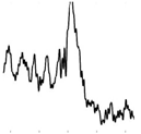 |  |
| Horizontals | 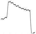 |  |
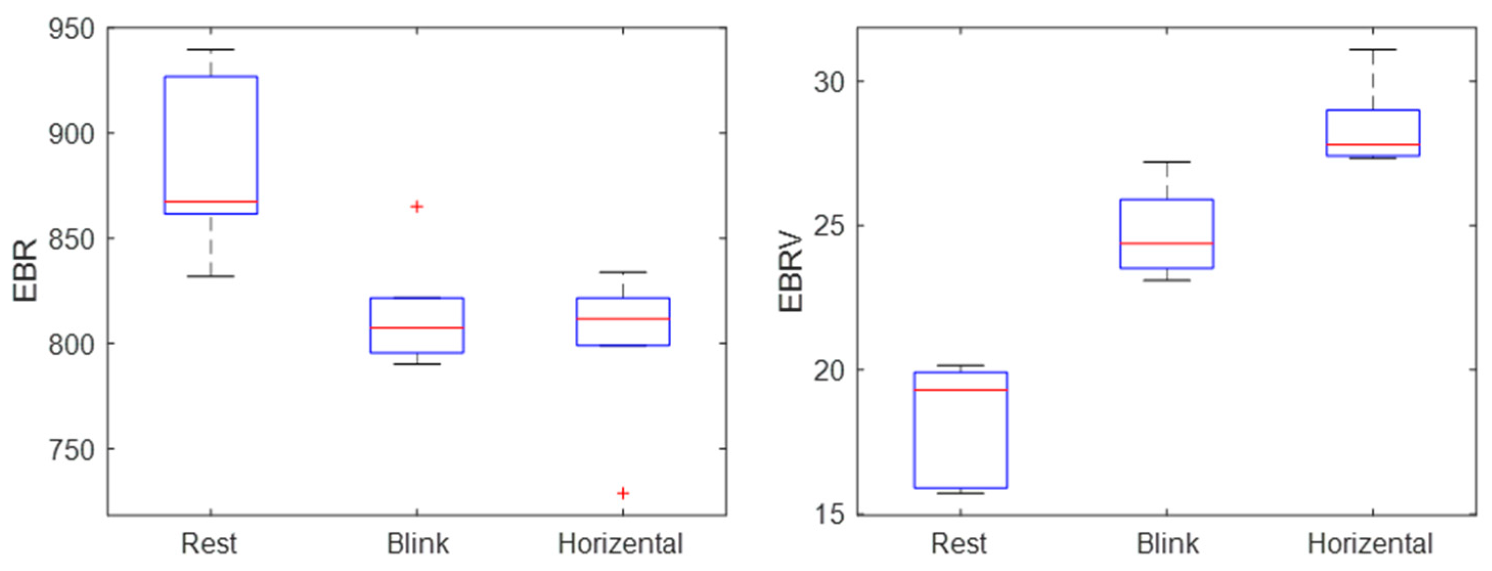
| Eye Motion Patterns | EBR (per min) | EBRV (ms) |
|---|---|---|
| “rest” | 882 | 18 |
| “blink” | 814 | 25 |
| “horizontal” | 801 | 28 |
Disclaimer/Publisher’s Note: The statements, opinions and data contained in all publications are solely those of the individual author(s) and contributor(s) and not of MDPI and/or the editor(s). MDPI and/or the editor(s) disclaim responsibility for any injury to people or property resulting from any ideas, methods, instructions or products referred to in the content. |
© 2023 by the authors. Licensee MDPI, Basel, Switzerland. This article is an open access article distributed under the terms and conditions of the Creative Commons Attribution (CC BY) license (https://creativecommons.org/licenses/by/4.0/).
Share and Cite
Moon, K.S.; Lee, S.Q.; Kang, J.S.; Hnat, A.; Karen, D.B. A Wireless Electrooculogram (EOG) Wearable Using Conductive Fiber Electrode. Electronics 2023, 12, 571. https://doi.org/10.3390/electronics12030571
Moon KS, Lee SQ, Kang JS, Hnat A, Karen DB. A Wireless Electrooculogram (EOG) Wearable Using Conductive Fiber Electrode. Electronics. 2023; 12(3):571. https://doi.org/10.3390/electronics12030571
Chicago/Turabian StyleMoon, Kee S., Sung Q. Lee, John S. Kang, Andrew Hnat, and Deepa B. Karen. 2023. "A Wireless Electrooculogram (EOG) Wearable Using Conductive Fiber Electrode" Electronics 12, no. 3: 571. https://doi.org/10.3390/electronics12030571