Article

Onboard Centralized ISL-Building Planning for LEO Satellite Constellation Networks

1
Beijing Institute of Spacecraft System Engineering, China Academy of Space Technology, Beijing 100094, China
2
College of Astronautics, Nanjing University of Aeronautics and Astronautics, Nanjing 211106, China
3
School of Computer Science and Engineering, Beihang University, Beijing 100191, China
*
Authors to whom correspondence should be addressed.
Electronics 2023, 12(3), 635; https://doi.org/10.3390/electronics12030635
Submission received: 15 December 2022 / Revised: 17 January 2023 / Accepted: 26 January 2023 / Published: 27 January 2023
(This article belongs to the Section Networks)

Abstract

:
Large-scale low earth orbit (LEO) satellite constellation projects are increasingly adopting inter-satellite links (ISLs) to enable their autonomous and collaborative operation. Due to the large number of satellite constellation network nodes and their continuous movement in orbit, the network nodes may not remain visible to each other at all times, so the ISL-building choices among satellites are diverse and vary with time. As a result, maintaining a network topology requires onboard planning and management. In this paper, we creatively propose an onboard centralized ISL-building planning scheme with the goal of autonomous topology management. A multi-antenna visibility calculation method that takes the antenna installation angle and the turntable rotation threshold into account is provided for the visibility calculation procedure. Additionally, the link-building planning process is modeled using integer linear programming (ILP); however, to tackle the computational complexity problem of ILP, a link-building planning method based on topology stability optimization is presented. The simulation results show that the proposed onboard centralized ISL-building planning scheme can operate among satellites to successfully realize network status collection, visibility calculation, link-building planning, and planning result distribution, as conducted by the dynamic primary satellite. Moreover, the inter-plane link-building planning method based on topology stability optimization improves the network topology stability on the basis of reducing the network delay.

1. Introduction

1.1. Background of the Study

At present, large-scale LEO satellite constellation projects are developing in the direction of networking [1,2,3,4] and intelligence. ISLs are also increasingly being used in the design of LEO satellite constellations, including Starlink [5], Telesat [6], and several others. ISLs are critical in decoupling ground station control, boosting constellation operating autonomy, and realizing the satellite network’s high reliability, timeliness, and self-organizing networking. Additionally, the use of an LEO satellite network with ISLs can reduce the latency compared to optical-fiber-based terrestrial networks [5]. The network nodes are not visible to each other at all times, due to the massive number of network nodes and their constant motion in orbit; thus, the selection for building ISLs is diverse and varies with time. Especially for inter-plane satellites, due to the relative motion among adjacent orbital planes, such that visibility cannot be maintained at all times, the links needs to be switched frequently and the topology varies dynamically. The disconnection of ISLs or frequent ISL switching will result in decreased constellation network performance. Therefore, optimized satellite network ISL-building planning is of great significance for realizing efficient satellite constellation networking.
ISL-building planning does not determine the number of satellites or antennas, and can be figuratively analogized to the process of building highways among a specified group of cities. After the satellite constellation configuration and the ISL antenna design are determined, it plans the optimal network topology in order to realize the construction of the constellation network communication infrastructure. After completing the topology construction, there is a network routing algorithm to realize the choice of data routing, which has been extensively studied and is beyond the scope of this paper. As the number of antenna terminals carried by a satellite is limited, it is required to choose links among the several visible ISLs while not exceeding the number of terminals carried. There are certain factors to be considered, in order to improve network topology performance. The optimization goals of building network topology include longer ISL duration, better topology stability, and lower network delay. Longer ISL duration and better topology stability effectively reduce the network route switching frequency and the possible packet loss during the ISL switching process, while lower network delay generally involves lower average and maximum network delays. The two indicators are essential metrics for describing network performance and providing a timeliness guarantee for inter-satellite data transmission.

1.2. Literature Review

To date, onboard network routing algorithms have been presented in some studies [7]; however, in most research on ISL-building planning, the topology is planned in advance at the ground station and then uploaded to the satellite in a timely manner [8]. There is currently no published research focused on realizing centralized network ISL-building planning onboard the satellite. The onboard implementation of the entire centralized network ISL-building planning process ensures greater ground station control decoupling and lower management latency. However, it also brings issues, such as the difficult collection of planning input parameters and limited computing resources. When a satellite performs tasks such as remote sensing and reconnaissance, its orbit and attitude change adaptively, which affect the visibility of ISLs, leading to different topology tables in each period. As such, the topology table in the previous period cannot be simply used in the next period. Moreover, during the satellite’s onboard operation, the satellites may be damaged and the ISL terminals may suddenly lose efficacy, which requires the primary satellite in the constellation to plan a new network topology in real time. These are necessary considerations in onboard ISL-building planning. Yan et al. [9] have proposed an ISL-building method suitable for distributed topology planning, which is a new idea for ISL-building planning. However, they did not describe the whole process of onboard distributed planning, nor did they explain the key processes such as the acquisition and synchronization of visibility calculation input information or the comparison and confirmation of planning results. From our perspective, there are still many problems to be solved in the field of distributed planning.
Several researchers have attempted to overcome the challenge of satellite network ISL-building planning by completing the computation process at the ground station. Most of these studies regard the satellite as a particle with an infinite visible angle [10], or assume that one satellite carries only one antenna [9,11], when calculating the visibility between ISL terminals, or that all of the installed antennas have the same installation direction and rotation threshold [2,12,13]. Furthermore, the satellite attitude in these studies is always regarded as a zero attitude. Some researchers simply assumed that the antennas used for the inter-plane ISLs are located at both sides of the pitch axis [13,14]. However, considering the shading of solar wings, cameras, antennas, and so on, the antennas used for the inter-plane ISLs may be installed at sides of the roll or yaw axes. Although these factors can substantially reduce the model complexity, they ignore the fact that, in future large-scale constellations, satellites need to carry more than one ISL terminal with different installation directions and construct several ISLs at the same time. Furthermore, the terminal installation direction and the turntable rotation angle thresholds significantly impact the ISL visibility. To sum up, the state-of-the-art articles did not take all the parameters of visibility calculation, such as the antenna installation direction, rotation threshold, and attitude, into consideration. Thus, it is necessary to study the visibility calculation method that can adapt to various satellite platforms.
Compared with the Geostationary Earth Orbit (GEO) constellations, the ISL-building planning problem is more challenging to solve when considering LEO constellations. This is because the relative position relationship among the satellites fluctuates regularly, resulting in more frequent ISL switches. Many works have used finite state automation (FSA) to solve this problem [11,15,16]; that is, the satellite network operation period is divided into fixed equal-length time segments, transforming the dynamic state into fixed states. For the entire constellation, each ISL visibility segment’s start and end time points may not be aligned with the fixed equal-length time segments. As a result, if the system period is divided into several time segments with the inappropriate length, many available visible time segments are partially or entirely cut off, resulting in decreased network performance. Therefore, choosing an appropriate length for the fixed equal-length time segments is essential.
The Manhattan Street Network (MSN) has been used to build ISLs in [17,18], and the commercial Starlink and Indium net networks prefer the MSN topology [19]. With the MSN, although the locations of satellites and ISLs change over time, the link relationship remains constant; that is, there is no dynamic link establishment and dismantlement. As the link length variation range and relative speed are easier to be managed, MSN is simple and beneficial and can be implemented in an onboard manner. It should be noted that different researchers have proposed different methods for MSN to obtain the fixed satellite pairs; for example, each satellite was connected to its closest neighbor in the same or adjacent plane in [19], while Karafolas and Baroni [17] selected the satellite with the same phase in the adjacent plane. The longest coverage time strategy (LCTS) in [12,20] has been employed to build ISLs. This method helps to improve the total number of ISLs in the network. It is a non-random method with low computational complexity, and is thus suitable for onboard link-building planning. Meanwhile, the integer linear programming (ILP) model has high computational complexity and is unsuitable for the onboard ISL-building planning. ISL-building planning with heuristic algorithms, such as the ant colony algorithm [21] and the simulated annealing algorithm [15,22], may require a large number of iterations, and these methods do not easily converge for large-scale networks [10]. Moreover, most of these methods are not deterministic, and the results obtained under the same input conditions may be different, which means that it is difficult to manage the network topology onboard. Therefore, they are not considered to be suitable in onboard ISL-building planning scenarios. Yan et al. [8], Hou et al. [11], Liu et al. [23] have proposed the use of graph matching methods to solve ISL-building planning problem. However, although these methods produce relatively good link terminal utilization and average point-to-point distance, the calculations are non deterministic and relatively complex. Therefore, they are also unsuitable for scenarios such as those where satellite computing and storage resources are extremely limited. Homssi et al. [24] provided insights into state-of-the-art artificial intelligence techniques across various layers of the communication link and stated that reinforcement learning techniques have been widely used in the traffic scheduling, resource allocation and network planning. Artificial intelligence will definitely become a very important technical approach to solving satellite network ISL-building planning and routing calculation in the future. However, the deep network learning or reinforcement learning need to deploy GPU (Graphics Processing Unit) or FPGA (Field-Programmable Gate Array) to realize learning and fast updating of parameters. The computational cost is unacceptable for low-cost satellites with only one single-core CPU (Central Processing Unit). During the deployment of network protocols or network algorithms onboard the satellites, two difficulties that need to be solved are dynamicity and lightweight. Among all these ISL-building algorithms, MSN forms a static topology, which does not solve the difficulty of dynamicity. Meanwhile, ILP, heuristic algorithms, graph matching and AI require high computing resources, so these algorithms do not solve the difficulty of lightweight, and they are not suitable for onboard ISL-building planning usage. LCTS is an algorithm with low computational complexity, but it is often used for inter-layer ISL-building rather than intra-layer inter-plane ISLs. Therefore, it is necessary to study the lightweight ISL-building planning algorithm to build an efficient dynamic satellite network topology.

1.3. Contributions

In this paper, we propose a centralized ISL-building planning scheme to address the problems identified in the previous works and the practical issues encountered in the development of current satellite constellation projects. The Walker Delta constellation is frequently used for LEO large-scale satellite constellation projects with ISLs [5,25,26,27], where ISLs among intra-plane satellites can be built continually. As a result, we focus on the building planning of inter-plane ISLs. This paper’s significant contributions are as follows:
  • For the first time, we provide an onboard centralized ISL-building planning scheme that enables efficient ISL-building planning onboard the satellite and decouples the entire planning process from ground station control;
  • We take into account that a satellite has multiple antenna terminals that can simultaneously participate in the ISL building. Furthermore, in order to approach the visibility calculation as closely as possible in the engineering implementation, we consider the impact of the terminal’s installation direction, the turntable’s rotation angle threshold, and the satellite’s attitudes on inter-plane visibility;
  • In order to address the problem of the high computational complexity of ILP, we propose a link-building planning method based on topology stability optimization for inter-plane ISLs. This method can be applied to situations in which satellite onboard computing resources are severely limited;
  • The ISL-building planning scheme proposed in this paper was evaluated through experimental simulation and compared with the current commonly used methods. Through the analysis of the results, it is found that the method can achieve positive results in performance indicators such as ISL switching frequency, topology stability, average delay, and maximum delay.
The remainder of this paper is organized as follows. The onboard centralized ISL-building planning scheme is described in Section 2. Section 3 and Section 4 cover the ISL-building planning scheme’s two key processes: visibility computation and inter-plane link building planning. Section 5 describes the experimental simulation of the ISL-building planning method proposed in this paper, and provides the analysis and evaluations of the results. Section 6 summarizes the paper.

2. Onboard Centralized ISL-Building Planning Scheme

Studies in the existing literature have conducted ISL-building planning at the ground station. Managing ISL-building planning at the ground station has the advantages of strong computing power and easy information collection; however, it also has obvious shortcomings such as poor constellation management autonomy and weak anti-destruction ability. In this paper, in order to adapt to future management autonomy needs for large-scale constellations, an onboard centralized ISL-building planning scheme is proposed for the first time, taking into account constraints such as limited onboard computing power and constrained information collection channels. As shown in Figure 1, the proposed satellite onboard centralized ISL-building planning scheme includes the following steps.
(1)
Link Status Collection by the Dynamic Primary Satellite
The ground station designates a satellite as the dynamic primary satellite. Alternatively, when the ground station is unreachable, the satellites in the constellation take turns as the dynamic primary satellite. The dynamic primary satellite collects link status information such as the orbital elements of each satellite in the constellation, the health status of the ISL terminals, and so on, as input parameters for the visibility calculation and link-building planning;
(2)
Visibility Calculation
Based on the acquired orbital elements and the health status of all ISL terminals in the constellation, the dynamic primary satellite performs orbit extrapolation and calculates the visible time segments between each two ISL terminals;
(3)
Link-building Planning
According to the calculated visible time segments between the ISL terminals, the dynamic primary satellite plans the network’s link connections and disconnection plan for the next period;
(4)
Planning Result Distribution and Link-building Implementation
The dynamic primary satellite distributes the planned network topology to all other satellites. According to the network topology table, each satellite implements link-building with other satellites at a specified time point;
(5)
Link Status Change Collection
In this period, the dynamic primary satellite collects the link status changes in real-time. If the changes happen, the primary satellite starts planning immediately and returns to the first step.
As shown in Figure 2, before the constellation enters the next period, it should return to the first step to plan the network topology for the next period.
Among the five steps, the first, fourth and fifth steps can be implemented among satellites through inter- and intra-satellite communication using currently mature techniques. The visibility calculation and link-building planning procedures are detailed in Section 3 and Section 4.

3. Visibility Calculation

As the inter-plane satellites move at high speeds, the ISLs need to be constantly switched and, as such, the network topology varies. Therefore, the visibility calculation must be performed before link-building planning. The pre-requisite for establishing an ISL is that two antennas are visible to each other.
Each satellite typically carries several ISL terminals in a large-scale low-orbit constellation network. Moreover, to ensure that the network can cover all satellite nodes, there is usually a situation where more than one ISL is built for one satellite simultaneously. Furthermore, ISL terminals are installed in different spots on the satellite, with varied installation directions, in order to form ISLs with satellites in different directions. As a result, to calculate the visibility more accurately and better meet the needs of engineering development, the antenna should be taken as the object of the visibility calculation rather than the satellite. Furthermore, the antenna installation direction and the turntable rotating threshold should be considered when the visibility calculation is performed, instead of viewing the satellite as a particle.
As shown in Figure 3, an ISL terminal is represented as a sub-node, and the number of sub-nodes contained in a network node is the number of terminals carried by the satellite. Then, the onboard computer should calculate the visibility among the sub-nodes of different nodes and build ISLs among the visible sub-nodes.
Before the visibility calculation, the satellite onboard computer calculates the period P of the relative positions of the nodes of the satellite constellation network, according to the orbit semi-major axis based on Kepler’s third law [28], as shown in (1):
P = 2 π a 3 G ( M 1 + M 2 ) ,
where a is the semi-major axis of the satellite’s elliptical orbit; G is the gravitational constant; M 1 and M 2 are the masses of the earth and the satellite, respectively; and P is also the planning period for the constellation network.
The visibility is represented by a Boolean matrix V, with the size of N × N × K , where N is the number of antennas in the constellation and K is the number of time segments in the period P. The antenna is the calculation object in the visibility calculation process. A denotes the set of all antennas in the constellation, and an antenna is written as i A = { 1 , 2 , , N } . v i , j , k = 1 indicates that the ith and jth antennas in the constellation are visible to each other at time segment k and the ISL can be built, while v i , j , k = 0 indicates that the two antennas are not mutually visible. Furthermore, R i and S i , for i A are the position and velocity vectors of the satellite, respectively, where the antenna i is placed in the J2000 coordinate system, and the maximum rotation half-angle of the link terminal’s turntable is θ i m a x . The first condition to be met in order to ensure visibility between i A and j A is that the earth does not block the connection between the two antennas. In this case, the distance between the connection and the center of the earth, as shown in Figure 4, should be greater than the radius of the earth, as which is represented by (2):
d = ( | R j | ) 2 ( | R j × ( R j R i ) | | R j R i | ) 2 > r E ,
where r E is the radius of the Earth.
Another factor that needs to be considered is that, after the ISL is built, the rotation angles of the two antenna turntables should be smaller than their turntable rotation capabilities. In the J2000 coordinate system, the vector from the antenna i to j is defined as (3):
Vector j , i , J 2000 = R j R i .
The vector from the antenna j to i is defined as (4):
Vector i , j , J 2000 = R i R j .
To calculate the rotation angle of the link terminal turntable, it is necessary to convert the above two vectors from the J2000 coordinate system to the vehicle velocity local horizontal (VVLH) coordinate system. The VVLH coordinate system is defined such that the origin is at the center of mass of the satellite; the Z-axis points toward the center of mass of the Earth from the origin; the X-axis is in the orbital plane and perpendicular to the Z-axis, along the direction of the satellite’s velocity; and the Y-axis follows the right-hand system and is opposite to the direction of angular momentum [29]. Thus, the transformation matrix for converting the J2000 coordinate system to the VVLH coordinate system is (5):
L = [ x y z ] T ,
where
x = y × z ,
y = R × S | R × S | ,
z = R | R | .
Thus, in the VVLH coordinate system, the vector pointing from i to j is given by
Vector j , i , VVLH = L j × Vector j , i , J 2000 .
Similarly, the vector pointing from j to i is given by
Vector i , j , VVLH = L i × Vector i , j , J 2000 .
The above two vectors in (9) and (10) also need to be converted from the VVLH coordinate system to the antenna coordinate system using the body coordinate system [30]. The Z-axis of the antenna coordinate system points in the antenna installation direction. The transformation matrices are L V V L H t o A n t , i and L V V L H t o A n t , j , respectively. The body coordinate system is the coordinate system that describes the satellite attitude. Thus, L V V L H t o A n t , i and L V V L H t o A n t , j can be expressed as (11) and (12):
L VVLHtoAnt , i = L BodytoAnt , i × L VVLHtoBody , i ,
L VVLHtoAnt , j = L BodytoAnt , j × L VVLHtoBody , j ,
where L VVLHtoBody , i and L VVLHtoBody , j are the transformation matrices from the VVLH coordinate system to the body coordinate system, determined according to the real-time attitude of the satellite.
Therefore, in the antenna coordinate system, the vector from antenna i to j and the vector from antenna j to i can be expressed as (13) and (14), respectively:
Vector j , i , Ant = L VVLHtoAnt × Vector j , i , VVLH ,
Vector i , j , Ant = L VVLHtoAnt × Vector i , j , VVLH .
Assuming that the antenna turntable has the same rotating range in all directions, the rotation angles at both ends of the link can be calculated after performing unit vector calculation, taking out the Z-axis component, and carrying out an inverse cosine calculation on vectors. The rotation angles of the antennas i and j are expressed as θ i and θ j , respectively, as shown in Figure 4. These two angles must be smaller than the antenna turntable’s rotation angle threshold to achieve the visibility requirement, as expressed by (15) and (16):
θ i = a c o s ( NORM ( Vector j , i , Ant ) . z ) < θ i m a x ,
θ j = a c o s ( NORM ( Vector i , j , Ant ) . z ) < θ j m a x .
Moreover, ISLs also have a link length threshold [18]. To ensure that the information is received intelligibly with an adequate signal-to-noise ratio, after the design of antennas has been completed, the link budget should be calculated, which considers all of the power gains and losses that a communication signal experiences. Through that, the maximum length should be satisfied when planning ISLs. Therefore, the final requirement for ensuring visibility is that the link length d i , j in Figure 4 should be smaller than the length threshold d i , j m a x , as shown in (17):
d i , j = | R j R i | < d i , j m a x .
Based on the same distance, optical systems guarantee a greater Shannon capacity than RF (Radio Frequency) systems [2].
Furthermore, FSA with equal-length time segments is used to describe and evaluate the visibility calculation. Through experiments, we chose the most appropriate time segment length that allows the visibility among the inter-plane links to be utilized to the greatest extent. The constellation network period is divided into fixed equal-length time segments and transform the dynamic state into fixed states. In time segment k, in order to consider that two antennas are visible, the requirement that the two antennas are visible at any time within time segment k must be met.
According to the above analysis, the visibility between any two antennas i A and j A in the constellation in time segment k is determined as (18):
v i , j , k = 1 , i f ( 2 ) a n d ( 15 ) a n d ( 16 ) a n d ( 17 ) a t a l l t h e t i m e p o i n t s i n k , 0 , o t h e r w i s e .

4. Link-Building Planning

The link-building planning algorithm is the core of the onboard centralized ISL-building planning scheme. In this section, within the scheme of the onboard centralized ISL-building planning, and on the basis of the visibility calculation, the link-building constraints, modeling, and onboard inter-plane link-building algorithm are discussed.

4.1. Link-Building Constrains

The link-building table is represented by a Boolean matrix T, with the size of N × N × K . The element t i , j , k = 1 indicates that the constellation’s ith antenna forms a link with the jth antenna in time segment k, while t i , j , k = 0 indicates that no link is built. The visible matrix V and the link-building matrix T are subject to the following constraints:
v i , j , k { 0 , 1 } , i , j A , k K ,
v i , j , k = v j , i , k , i , j , k ,
t i , j , k { 0 , 1 } , i , j A , k K ,
t i , j , k = t j , i , k , i , j , k ,
v i , j , k t i , j , k 0 , i , j , k ,
where K is the number of time segments in the period P, and k = { 1 , 2 , , K } .
Equations (20) and (22) show that both the visibility matrix and the link-building matrix have symmetry, indicating that the ISL has no directionality, and that the visible and link-building relationships between i and j are the same between j and i. The link between i and j must be constructed based on the fact that i and j are mutually visible, as shown in (23).
In addition, we impose some constraints on the ISL-building for the link-building table T; namely,
j Z i t i , j , k 1 , i , k ,
j Z i t i , j , k = 0 , i , k ,
where Z ( i ) represents the set of antennas in the plane adjacent to the plane where i is located; (24) indicates that, at the same time, one antenna can only build at most one link with an antenna in the adjacent plane; and (25) indicates that the antenna cannot build a link with antennas in a non-adjacent plane at any time. These two constraints ensure that ISLs are only formed between antennas carried by satellites on adjacent orbital planes.

4.2. Modeling

In the preceding subsections, we clearly described how to generate the link visibility three-dimensional Boolean matrix and the network ISL-building planning constraints. Based on these constraints, in this subsection, we model the link-building planning problem. The planned topology should have the characteristics of low link switching frequency, high topology stability, low average delay, and low maximum delay. To achieve these optimization goals, the problem is modeled as shown in (26):
min T k K λ p k + η q k + μ h k , max + σ h k , mean ,
where λ is the weight of the number of link-switches p k , compared with the previous time segment; η is the weight of the parameter that indicating whether there is a topology change q k , compared with the previous time segment (we define that the topology is changed when at least a single ISL changes); μ is the weight of the maximum end-to-end delay h k , max ; σ is the weight of the average end-to-end delay h k , mean ; and λ , η , μ and σ are determined based on the usage requirements of different constellations. If one constellation has strong demand for low delay, μ and σ should be set to large numbers; meanwhile, if a stable topology is important for the constellation, the weights λ and η should be large. These weights remain same among the periods.
The smaller the number of link switches p k and topology changes q k , the higher the topology stability.
Satellite networks are not only used for ground communications, but also for efficient collaboration among satellites, especially for remote sensing satellite constellations. In some use-cases, each ISL in the constellation is used and plays an important role. Therefore, the link-switching number and ISL duration can be considered as important performance indicators to characterize the network topology.
The maximum end-to-end delay h k , max can be further expressed as
h k , max = max i , j h i , j , k ,
where h i , j , k represents the delay from node i to node j in the kth time segment. The average end-to-end delay h k , mean can be expressed as
h k , mean = i N j N h i , j , k N × N .
In this study, the end-to-end delay includes the table-lookup delays of all forwarding nodes and ISL latency of wireless signal propagation on the routing path. For the end-to-end delay, we adopt the hop-count metric [14,31,32].
Equation (26) falls into the category of ILP that is NP-hard and, so, the time complexity to find the optimal solution for such a multi-constrained integer linear programming problem is very high [8,10]. The topology T is a three-dimensional matrix; thus, the time complexity to solve this problem is O ( 2 N × N × K ) , which is unacceptable in the context of limited onboard computing resources. When N = 32 and K = 32 , this problem may take more than years, even when using a supercomputer. As a result, an algorithm with lower time complexity is required to realize optimal link-building planning without compromising the performance.

4.3. Link-Building Planning Method Based on Topology Stability Optimization

We provide a link-building planning method based on topology stability optimization (LPTSO) in this subsection, which can handle the link-building planning problem while providing very low algorithm time complexity. This method can improve topology performance, thus enabling satellites to execute link-building planning onboard autonomously.
As discussed in Section 3, the satellite onboard computer calculates the position vector R i and the velocity vector S i for i A in the period using the orbit extrapolation algorithm. Furthermore, the calculation of the visibility Boolean matrix in the period P takes it into account the installation positions of the antennas and the antenna turntable rotating thresholds, in order to ensure that multiple antennas with different installation positions on one satellite can build ISLs at the same time.
The preliminary simulation shows that, in most of the LEO Walker Delta constellation, adjacent satellites in the same plane are visible to each other continuously [13,33]. As a result, to build a more stable topology, in our method, all satellites build ISLs with the adjacent satellites permanently and form a ring in a plane; that is, the ith satellite in plane p builds ISLs with the ( i 1 ) th satellite and the ( i + 1 ) th satellite in plane p.
However, the satellites in adjacent planes may not remain visible to each other and, so, inter-plane ISLs should be planned. The pseudo-code of the inter-plane link-building planning method discussed in this subsection is expressed by Algorithm 1.
Step one. From the three-dimensional Boolean visibility matrix, calculate the total ISL visible duration for any two inter-plane satellite antennas in the constellation in period P; namely,
v i s i b l e _ d u r a t i o n i , j = k K v i , j , k ,
where v i s i b l e _ d u r a t i o n i , j is the sum of the visible time segments in period P between antenna i and antenna j.
Algorithm 1: Link-building_Planning ( V , K )
Require: 
The visibility matrix of V and the number of time segments of K
Ensure: 
The planning result of p l a n n i n g _ r e s
  1:
for  i : N   do
  2:
    for  j : N  do
  3:
         v i s i b l e _ d u r a t i o n i , j = k K v i , j , k ;
  4:
    end for
  5:
end for
  6:
for  i : N   do
  7:
     i f = arg max Z ( i ) v i s i b l e _ d u r a t i o n i , Z ( i ) ;
  8:
    for  j : N  do
  9:
        if  j i f  then
10:
           for  k : K  do
11:
                v i , j , k = F A L S E ;
12:
           end for
13:
        end if
14:
    end for
15:
end for
16:
for  k : K do
17:
    for  i : N  do
18:
         p l a n n i n g _ r e s k , i = arg max j l a t e r _ b r o k e n ( v i , j , k ) ;
19:
    end for
20:
end for
Step two. For any antenna i A in the constellation, select an antenna i f with the longest link duration sum in the period in each of antenna i’s two adjacent orbital planes; namely,
i f = arg max Z ( i ) v i s i b l e _ d u r a t i o n i , Z ( i ) .
These two antennas can be defined as the first-choice antennas of antenna i, and the associated links are defined as the first-choice ISLs.
In addition, the link visibility between antenna i and its non-first-choice antennas in the link-visibility Boolean matrix should be set as invisible at all times in the period; that is, non-first-choice ISLs are not considered in the link-building planning of inter-plane ISLs, as represented by
v i , j , k = 0 , i f j i f .
Step three. For each unused antenna in the constellation, select one unused antenna that is visible to it at this time, and keep the inter-plane ISL until the ISL is invisible. If there is more than one unused antenna visible simultaneously, select the antenna with the later broken visibility to establish an ISL with it.
Compared with the time complexity of ILP, the time complexity of the method stated in this subsection is O ( N × N × K ) , allowing it to reasonably be solved on a satellite onboard computer. In our simulation, when N = 32 and K = 32 , the onboard computer took less than one second to complete the computation.

5. Performance Evaluation

5.1. Simulation Setup

To compare the performance of the method proposed in this paper and several common methods used in related works, we developed a simulation scenario involving which is a Walker Delta 32/4/1 constellation; that is, there are four planes in the constellation, with eight satellites per plane. The orbital elements of one of the satellites in the constellation are stated in Table 1. The simulation period was 7800 s, approximately the constellation’s repeat cycle.
Furthermore, there were four ISL terminals in each satellite. The installation direction and turntable rotation half-angle of each ISL terminal are stated in Table 2.
The preliminary simulation indicates that, in the constellation, all satellites on the same plane can use ISL terminal I and ISL terminal II to build ISLs continuously and form a ring. Nevertheless, on the other hand, the ISLs between adjacent planes need to be switched.
Furthermore, to verify the applicability of the proposed link-building planning method, we developed a large-scale constellation scenario, as described in Section 5.4 below.
All the simulations were performed on a computer typically used on satellites, having a 50 MHz CPU and 512 MB RAM.

5.2. Influence of Different Value of Time Segment Length

As mentioned in the previous sections, in some works, FSA has been used to describe the ISL-building planning problem in one period [11,15,16]. The system period is divided into several equal-length time segments, and a fixed network topology is maintained in each time segment. The ISLs visible at each time in the time segment are considered to be visible in the time segment. Generally speaking, in the process of visibility calculation, the start and end time points of the visible time segments are not aligned with the equal-length time segments of the FSA. If the time segment length is too large, some visible time segments that could have been used to build ISLs would be wasted, resulting in a reduction in the number of ISLs and, consequently, degradation of the network topology performance. However, on the other hand, if the time segment length is too small, the whole network topology may switch frequently, also reducing the network performance. Therefore, selecting an appropriate time segment length is important, which can allow for a reduction of the network topology switching frequency without increasing the network delay. Another way to process the time segment of FSA is not to use an equal-length time segment; that is, the calculated visible time segments are used to build ISLs without alignment to the equal-length time segments. In a system with a time accuracy of one second, not using an equal-length time segment is equivalent to the equal-length time segment with a length of one second.
In order to select the appropriate time segment length in FSA for the method proposed in this paper, in this subsection, we compared the implementation results of the method under different time segment lengths. Common time segment lengths are 300 s or 600 s [11,16]. In the simulation, the time segment length was set to 150 s (LPTSO-150s), 300 s (LPTSO-300s), 450 s (LPTSO-450s), 600 s (LPTSO-600s), 750 s (LPTSO-750s), and an unequal-length time segment (LPTSO-1s). In the Walker Delta 32/4/1 constellation, based on the various different time segment lengths, the method proposed in this paper was implemented, and the network topology performance metrics such as ISL duration, topology duration, average delay, and maximum delay, were compared.
Figure 5 shows the experimental results for average ISL duration and average topology duration under different time segment lengths. We can see, from the figure, that when the time segment was less than or equal to 300 s, the average ISL duration and the average topology duration were almost consistent. When the time segment length was greater than 300 s, with an increase in the time segment length, the average ISL duration decreases while the average topology duration increased. This is because the topology duration in the initial visibility calculation results was close to 300 s. Therefore, when the time segment was less than or equal to 300 s, there was almost no loss of visible time segment when aligning the start and end time of the visible time segments to the equal-length time segments. When the time slice was greater than 300 s, during the alignment process, many available visible time segments were partially or completely cut off, resulting in decreased average ISL duration.
Figure 6 shows the experimental results for maximum delay and average delay under different time segment lengths. We can see, from the figure, that when the time segment was less than or equal to 300 s, the maximum delay and average delay were consistent. When the time segment length was greater than 300 s, the maximum delay and average delay increased, while the network performances decreased as the time segment length increased. This further confirms the previous statement: when the time segment length was greater than 300 s, during the process of alignment to the equal-length time segments, many available visible time segments were partially or completely cut off. The number of ISLs built in the network decreased, thus increasing the maximum delay and average delay.
The experimental results indicate that, in order to improve the stability of the network topology as much as possible without reducing the network transmission performance, the time segment length should be set to 300 s, which allows for a better trade-off between topology stability and network performance. Therefore, we used 300 s as the time segment length of LPTSO FSA for the Walker Delta 32/4/1 constellation.

5.3. Performance in Small-Scale Constellation

Next, we evaluated and analyzed the onboard centralized network ISL-building planning in the Walker Delta 32/4/1 constellation.
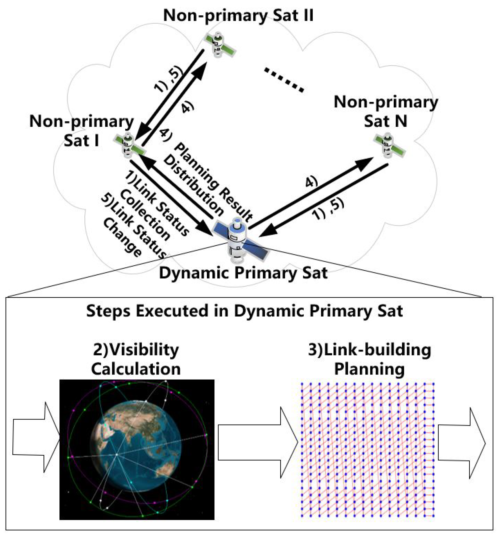
Under the small-scale constellation configuration, we simulated the onboard centralized network ISL-building planning scheme. The results indicated that each satellite in the constellation can act as the dynamic primary satellite for onboard centralized ISL-building planning, which can complete ISLs terminal status collection, visibility calculation, link-building planning, and the link-building planning table distribution. The non-primary satellites can send their terminal status, retrieve the link-building planning table from the primary satellite, and control the ISL terminal to rotate and build the ISLs, according to the link-building planning table.
The link-building planning process is the core of the onboard centralized network ISL-building planning scheme. Therefore, in the following, we mainly analyze and compare the link-building planning results.
Figure 7 shows the link-building planning results for the Walker Delta 32/4/1 constellation using the LPTSO proposed in this paper. The figure shows four topology snapshots, and each one indicates the ISL-building status. The figure is also a graphic display of the planning table that are generated and distributed by the primary satellite. We can see, from the figure, that the pattern is similar to the pattern of MSN, in which the outcomes are regular, making it simple to manage, maintain, and debug onboard. It is essential to increase the satellite network’s simplicity of use and improve the reliability of the constellation. On the other hand, different from MSN, the topology generated by LPTSO is not a static mesh-like topology, and it presents a limited dynamic pattern. Every sub-node has a small-size optional pair set, and every option in the set is high-quality one, such that the network topology can improve the network topology stability on the premise of reducing network delay.
Table 3 provides the ISL duration, topology duration, average delay, maximum delay, and other performance indicators of the network topology in a period, consistent with the analysis in the previous subsection.
As stated in Section 1, ILP, heuristic algorithms, and graph matching algorithms are unsuitable for onboard centralized ISL-building planning. In this subsection, we compare the results of the link-building planning method proposed in this paper with those of MSN and LCTS.
Figure 8 shows a comparison of the average ISL duration under different strategies. The average ISL duration of LPTSO was similar to that of MSN and much higher than that of LCTS. This is because, unlike LPTSO and MSN, LCTS builds some ISLs with shorter visible time segments, resulting in a shorter average duration of ISLs and a larger standard deviation of duration.
Figure 9 and Figure 10 illustrate the topology switching and topology duration in a period when using three methods. The duration length of each topology snapshot of LPTSO was the same (i.e., 300 s). The average duration of MSN was shorter, while the standard deviation was larger, partly because MSN does not use equal-length time segments. On the other hand, the average duration of MSN is also shorter than that of LPTSO-1s, as a given antenna competes with other antennas to build an ISL with LPTSO-1s. Thus, breaking an ISL often occurs at the same time as building another ISL, which decreases the network topology switching frequency. However, with MSN, once an ISL is visible, it is built immediately, producing many fragmented topology snapshots. In addition, the average duration of LCTS is short, while its standard deviation is large. This is because LCTS builds ISLs with different lengths of visible time segments. Although the total number of ISLs is high, frequent network topology switching occurs.
Figure 11 and Figure 12 show the average and maximum delays with the three methods in a period, respectively. The horizontal axes for the two figures are the topology snapshot number. As the LPTSO topology lasted for a longer time and there were fewer topology snapshots in the period, the lines for LPTSO in the figures are shorter. It can be seen from the figures that the average delay and maximum delay of LPTSO were small and stable over the period. As MSN builds ISLs between fixed ISL terminals, the number of ISLs in the network was lower and, so, the average and maximum delay were both high. The number of ISLs in the network with LCTS is large, making the average delay close to or slightly smaller than that of LPTSO in most snapshots. However, due to the frequent and unstable ISL switching in the time dimension, the average delay fluctuated greatly. Furthermore, the ISLs with LCTS were unevenly distributed among different adjacent planes, so the maximum delay was higher than that of LPTSO.

5.4. Link-Building Planning Performance in Large-Scale Constellation

In order to verify the applicability of the link-building planning method proposed in this paper to a large-scale constellation, we evaluated and analyzed the results of the proposed onboard network ISL-building planning method based on a Walker Delta 500/20/1 constellation; that is, there were 20 planes with 25 satellites per plane. The orbital elements of the seed satellite in the constellation are stated in Table 4. Again, four ISL terminals per satellite were considered. The installation direction and turntable rotation half-angle of each ISL terminal were as stated in Table 2. The simulation period was 7200 s, approximately the constellation’s repeat cycle.
Figure 13 compares the maximum/average/minimum ISL duration of two constellations, from which it can be seen that the average ISL duration of Walker Delta 32/4/1 was similar to that of Walker Delta 500/20/1. Figure 14 compares the topology switches of two constellations. The topology switching time points of the two constellations were fully aligned, and the duration of each topology snapshot was 300 s.
Table 5 compares the average linked ratio, maximum delay, and average delay of the two constellations. It should be noted that the average linked ratio refers to the ratio between the number of inter-plane ISLs built and the theoretical maximum number of inter-plane ISLs in the constellation. The linked ratio of the topology planned by this method in the two constellations was similar. Due to the large scale of the Walker Delta 500/20/1 constellation, the average and maximum delays were relatively large.
According to the above analysis, the performance indicators, such as ISL duration, topology duration, and linked ratio of the topology planned by LPTSO-300s for Walker Delta 32/4/1 and Walker Delta 500/20/1 constellations, were the same or similar, demonstrating that LPTSO-300s is still applicable to large-scale constellations.

6. Conclusions

ISLs are increasingly being used in LEO constellation projects. In this context, achieving efficient and optimized satellite network ISL-building planning for ISLs is of great significance for realizing efficient LEO satellite constellation networking. For the first time, we implemented an onboard centralized network ISL-building planning method, thus decoupling ground station control and enhancing the autonomy of network management. We provided a solution to the visibility calculation process in the onboard centralized ISL-building planning scheme by using the antenna as the calculation object. The visibility calculation process takes into account the antenna installation angle, the turntable rotation threshold, and the satellite attitude. Furthermore, the visibility calculation realizes the simultaneous link-building of multiple antennas, making it closer to the engineering implementation. Then, the link-building planning process in the onboard ISL-building planning management scheme was modeled using ILP. In order to solve the problem that ILP computational complexity is too high, making it unsuitable for onboard deployment, we presented a link-building planning method based on topology stability optimization, which significantly increased the network’s usability. The simulation results demonstrated that any satellite in the satellite network can implement the onboard centralized ISL-building planning as the dynamic primary satellite. Furthermore, ISL visibility can be calculated correctly. Moreover, the link-building planning method based on topology stability optimization improves the network topology stability on the premise of reducing network delay, and the overall performance was better than MSN and LCTS in experiments.
Our work will be applied to the engineering development of small- and large-scale LEO satellite networks, enabling the deployment of satellite networks with a stable and low-delay network topology. The industry will be led, by the onboard centralized ISL-building planning scheme, to move satellite network ISL-building planning from the ground station to the satellite and further advance the development of the satellite systems in the direction of networking and intelligence. Furthermore, engineering development will be supported by the visibility calculation, which considers the antenna installation angle and the turntable rotation threshold. Additionally, our link-building planning method based on topology stability offers a more practical, user-friendly, and efficient solution.
The onboard centralized ISL-building planning scheme still has shortcomings, regarding its relatively low reliability and robustness. If the primary satellite is lost by accident, it may take some time to re-select the temporary primary satellite by the ground station. During this switching time, the constellation will lose control of the network topology. In the future, we will further study the onboard multi-primary centralized/distributed ISL-building planning and management scheme, with the aim of achieving a highly reliable and error-tolerant network topology.

Author Contributions

Conceptualization, L.Q., H.Y. and Y.X.; Methodology, L.Q. and X.Z.; Software, L.Q. and X.Z.; Validation, H.Y. and Y.X.; Formal analysis, L.Q., H.Y. and Y.X.; Writing—original draft preparation, L.Q. and X.Z.; Writing—review and editing, H.Y., L.W. and X.W.; Supervision, L.W. and X.W. All authors have read and agreed to the published version of the manuscript.

Funding

This research was funded by Qian Xuesen Youth Innovation Fund of China Aerospace Science and Technology Corporation.

Data Availability Statement

All data generated or analyzed during this research is included in this article.

Conflicts of Interest

The authors declare no conflict of interest.

Abbreviations

The following abbreviations are used in this manuscript:
LEOLow earth orbit
ISLInter-satellite link
ILPInteger linear programming
GEOGeostationary earth orbit
FSAFinite state automation
MSNManhattan street network
LCTSLongest coverage time strategy
GPUGraphics processing unit
FPGAField-programming gate array
CPUCentral processing unit
AIArtificial Intelligence
VVLHVehicle velocity local horizontal
RFRadio Frequency
LPTSOLink-building planning method based on topology stability optimization
RAMRandom access memory

References

  1. Okati, N.; Riihonen, T. Modeling and analysis of LEO mega-constellations as nonhomogeneous Poisson point processes. In Proceedings of the 2021 IEEE 93rd Vehicular Technology Conference (VTC2021-Spring), Helsinki, Finland, 25–28 April 2021; pp. 1–5. [Google Scholar]
  2. Lee, Y.; Choi, J.P. Connectivity analysis of mega-constellation satellite networks with optical intersatellite links. IEEE Trans. Aerosp. Electron. Syst. 2021, 57, 4213–4226. [Google Scholar] [CrossRef]
  3. Giordani, M.; Zorzi, M. Non-terrestrial networks in the 6G era: Challenges and opportunities. IEEE Netw. 2020, 35, 244–251. [Google Scholar] [CrossRef]
  4. Evans, B.; Werner, M.; Lutz, E.; Bousquet, M.; Corazza, G.E.; Maral, G.; Rumeau, R. Integration of satellite and terrestrial systems in future multimedia communications. IEEE Wirel. Commun. 2005, 12, 72–80. [Google Scholar] [CrossRef] [Green Version]
  5. Al Homssi, B.; Al-Hourani, A.; Wang, K.; Conder, P.; Kandeepan, S.; Choi, J.; Allen, B.; Moores, B. Next Generation Mega Satellite Networks for Access Equality: Opportunities, Challenges, and Performance. IEEE Commun. Mag. 2022, 60, 18–24. [Google Scholar] [CrossRef]
  6. Pachler, N.; del Portillo, I.; Crawley, E.F.; Cameron, B.G. An updated comparison of four low earth orbit satellite constellation systems to provide global broadband. In Proceedings of the 2021 IEEE International Conference on Communications Workshops (ICC Workshops), Montreal, QC, Canada, 14–23 June 2021; pp. 1–7. [Google Scholar]
  7. Ekici, E.; Akyildiz, I.F.; Bender, M.D. A distributed routing algorithm for datagram traffic in LEO satellite networks. IEEE/ACM Trans. Netw. 2001, 9, 137–147. [Google Scholar] [CrossRef]
  8. Yan, Z.; Zhao, K.; Li, W.; Kang, C.; Zheng, J.; Yang, H.; Du, S. Topology Design for GNSSs Under Polling Mechanism Considering Both Inter-Satellite Links and Ground-Satellite Links. IEEE Trans. Veh. Technol. 2021, 71, 2084–2097. [Google Scholar] [CrossRef]
  9. Yan, Z.; Fraire, J.A.; Zhao, K.; Yan, H.; Madoery, P.G.; Li, W.; Yang, H. Distributed contact plan design for GNSSs. IEEE Trans. Aerosp. Electron. Syst. 2019, 56, 660–672. [Google Scholar] [CrossRef]
  10. Bhattacherjee, D.; Singla, A. Network topology design at 27,000 km/h. In Proceedings of the 15th International Conference on Emerging Networking Experiments and Technologies, Orlando, FL, USA, 9–12 December 2019; pp. 341–354. [Google Scholar]
  11. Hou, Z.; Yi, X.; Zhao, Y.; Li, C.; Xie, Y. Contact plan design for navigation satellite network based on maximum matching. In Proceedings of the 2nd International Conference on Vision, Image and Signal Processing, Las Vegas, NV, USA, 27–29 August 2018; pp. 1–6. [Google Scholar]
  12. Yan, H.; Zhang, Y.; Zhang, R.; Zeng, L.; Jia, W. Inter-layer topology design for IGSO/MEO double-layered satellite network with the consideration of beam coverage. In Proceedings of the 2018 IEEE 18th International Conference on Communication Technology (ICCT), Chongqing, China, 8–11 October 2018; pp. 750–754. [Google Scholar]
  13. Leyva-Mayorga, I.; Soret, B.; Popovski, P. Inter-plane inter-satellite connectivity in dense LEO constellations. IEEE Trans. Wirel. Commun. 2021, 20, 3430–3443. [Google Scholar] [CrossRef]
  14. Lu, Y.; Zhao, Y.; Sun, F.; Yang, F.; Liang, R.; Shen, J.; Zuo, Z. Enhancing transmission efficiency of mega-constellation LEO satellite networks. IEEE Trans. Veh. Technol. 2022, 71, 13210–13225. [Google Scholar] [CrossRef]
  15. Tai, J.; Lv, J.; Wu, X.; Song, T.; Zhang, Q.; Xiang, Y.; Sun, J. Topology optimization Design of LEO Satellite Network. In Proceedings of the 2019 Chinese Control Conference (CCC), Guangzhou, China, 27–30 July 2019; pp. 8154–8159. [Google Scholar]
  16. Chang, H.S.; Kim, B.W.; Lee, C.G.; Min, S.L.; Choi, Y.; Yang, H.S.; Kim, D.N.; Kim, C.S. FSA-based link assignment and routing in low-earth orbit satellite networks. IEEE Trans. Veh. Technol. 1998, 47, 1037–1048. [Google Scholar] [CrossRef] [Green Version]
  17. Karafolas, N.; Baroni, S. Optical satellite networks. J. Light. Technol. 2000, 18, 1792. [Google Scholar] [CrossRef]
  18. Suzuki, R.; Yasuda, Y. Study on ISL network structure in LEO satellite communication systems. Acta Astronaut. 2007, 61, 648–658. [Google Scholar] [CrossRef]
  19. Wang, W.; Zhao, Y.; Zhang, Y.; He, X.; Liu, Y.; Zhang, J. Inter-Satellite Laser Link Planning for Reliable Topology Design in Optical Satellite Networks: A Networking Perspective. IEEE Trans. Netw. Serv. Manag. 2022, 19, 2612–2624. [Google Scholar] [CrossRef]
  20. Chen, C.; Ekici, E.; Akyildiz, I.F. Satellite grouping and routing protocol for LEO/MEO satellite IP networks. In Proceedings of the 5th ACM International Workshop on Wireless Mobile Multimedia, Atlanta, GA, USA, 28 September 2002; pp. 109–116. [Google Scholar]
  21. Dorigo, M.; Birattari, M.; Stutzle, T. Ant colony optimization. IEEE Comput. Intell. Mag. 2006, 1, 28–39. [Google Scholar] [CrossRef]
  22. Li, L.; Wei, W.; Wang, K.; Ren, W.; Wang, S. Traffic-aware Link Assignment in GEO Satellite Communication Networks. In Proceedings of the 2021 IEEE International Conference on Communication, Networks and Satellite (COMNETSAT), Purwokerto, Indonesia, 17–18 July 2021; pp. 1–5. [Google Scholar]
  23. Liu, Z.; Guo, W.; Deng, C.; Hu, W.; Zhao, Y. Perfect match model-based link assignment to design topology for satellite constellation system. Int. J. Satell. Commun. Netw. 2016, 34, 263–276. [Google Scholar] [CrossRef]
  24. Homssi, B.A.; Dakic, K.; Wang, K.; Alpcan, T.; Allen, B.; Kandeepan, S.; Al-Hourani, A.; Saad, W. Artificial Intelligence Techniques for Next-Generation Mega Satellite Networks. arXiv 2022, arXiv:2207.00414. [Google Scholar]
  25. Suzuki, R.; Motoyoshi, S.; Yasuda, Y. A study of constellation for LEO satellite network. In Proceedings of the 22nd AIAA International Communications Satellite Systems Conference & Exhibit 2004 (ICSSC), Monterey, CA, USA, 9–12 May 2004; p. 3236. [Google Scholar]
  26. Su, Y.; Liu, Y.; Zhou, Y.; Yuan, J.; Cao, H.; Shi, J. Broadband LEO satellite communications: Architectures and key technologies. IEEE Wirel. Commun. 2019, 26, 55–61. [Google Scholar] [CrossRef]
  27. Shin, J.; Park, S.Y.; Son, J.; Song, S.C. Design of Regional Coverage Low Earth Orbit (LEO) Constellation with Optimal Inclination. J. Astron. Space Sci. 2021, 38, 217–227. [Google Scholar]
  28. Kepler, J. What Is Satellite Meteorology? IMD: Pune, India, 1956. [Google Scholar]
  29. Luo, J.; Chen, L.; Tang, G.-J. Attitude optimization of optical space surveillance satellite to observe specific geostationary orbit object. Optik 2016, 127, 11706–11716. [Google Scholar] [CrossRef]
  30. Cai, G.; Chen, B.M.; Lee, T.H. Coordinate Systems and Transformations. In Unmanned Rotorcraft Systems; Springer: London, UK, 2011; pp. 23–34. [Google Scholar]
  31. Chen, Q.; Giambene, G.; Yang, L.; Fan, C.; Chen, X. Analysis of inter-satellite link paths for LEO mega-constellation networks. IEEE Trans. Veh. Technol. 2021, 70, 2743–2755. [Google Scholar] [CrossRef]
  32. Lu, Y.; Zhao, Y.; Sun, F.; Li, H.; Wang, D. Dynamic fault-tolerant routing based on FSA for LEO satellite networks. IEEE Trans. Comput. 2012, 62, 1945–1958. [Google Scholar] [CrossRef]
  33. Zhu, Q.; Tao, H.; Cao, Y.; Li, X. Laser Inter-Satellite Link Visibility and Topology Optimization for Mega Constellation. Electronics 2022, 11, 2232. [Google Scholar] [CrossRef]
Figure 1. Satellite onboard centralized ISL-building planning scheme.
Electronics 12 00635 g001
Figure 2. Flow chart of onboard centralized ISL-building planning scheme.
Electronics 12 00635 g002
Figure 3. Representing ISL terminals as sub-nodes.
Electronics 12 00635 g003
Figure 4. Visibility calculation conditions.
Electronics 12 00635 g004
Figure 5. ISL and topology duration with different value of time segment lengths.
Electronics 12 00635 g005
Figure 6. Network average delay and maximum delay with different time segment lengths.
Electronics 12 00635 g006
Figure 7. Topology snapshots of the link-building planning with LPTSO.
Electronics 12 00635 g007
Figure 8. ISL duration with three different methods.
Electronics 12 00635 g008
Figure 9. Topology switches with three different methods.
Electronics 12 00635 g009
Figure 10. Topology duration with three different methods.
Electronics 12 00635 g010
Figure 11. Average Delay with three different methods.
Electronics 12 00635 g011
Figure 12. Maximum delay with three different methods.
Electronics 12 00635 g012
Figure 13. ISL duration of the two constellations.
Electronics 12 00635 g013
Figure 14. Topology switches of the two constellations.
Electronics 12 00635 g014
Table 1. Orbital elements of the seed satellite in Walker Delta 32/4/1 constellation.
Semi-Major Axis8500 km
Eccentricity0.0000
Inclination60
Longitude of the ascending node 0
Argument of periapsis 0
Mean anomaly at epoch 0
Table 2. The installation direction and turntable rotation half-angle of each ISL terminal.
AzimuthElevationHalf-Angle
ISL Terminal I 0 0 89
ISL Terminal II 180 0 89
ISL Terminal III 90 0 89
ISL Terminal IV 90 0 89
Table 3. Performance of link-building planning with LPTSO.
Value
Avg. ISL Duration3168 s
Avg. Topology Duration300 s
Avg. Delay2.74 hops
Max. Delay4.00 hops
Table 4. Orbital elements of the seed satellite in Walker Delta 500/20/1 constellation.
Semi-major axis8059 km
Eccentricity0.0000
Inclination 55
Longitude of the ascending node 0
Argument of periapsis 0
Mean anomaly at epoch 0
Table 5. The average linked ratio, the average delay, and maximum delay of the two constellations.
Walker Delta 32/4/1Walker Delta 500/20/1
Avg. Linked Ratio82%89%
Avg. Delay2.74 hops11.18 hops
Max. Delay4.00 hops20 hops
Disclaimer/Publisher’s Note: The statements, opinions and data contained in all publications are solely those of the individual author(s) and contributor(s) and not of MDPI and/or the editor(s). MDPI and/or the editor(s) disclaim responsibility for any injury to people or property resulting from any ideas, methods, instructions or products referred to in the content.

