Article

Research on Efficient Handover Mechanism for Cubic Receiver in Visible Light Communication

1
Cyberspace Security Academy, Zhengzhou University, Zhengzhou 450000, China
2
Communication Department, Information Engineering University, Zhengzhou 450000, China
3
Zhengzhou Xinda Institute of Advanced Technology, Zhengzhou 450000, China
*
Author to whom correspondence should be addressed.
Electronics 2023, 12(3), 701; https://doi.org/10.3390/electronics12030701
Submission received: 1 December 2022 / Revised: 5 January 2023 / Accepted: 20 January 2023 / Published: 31 January 2023
(This article belongs to the Section Microwave and Wireless Communications)

Abstract

:
Visible light communication (VLC) has the advantages of rich spectrum resources, endogenous safety and anti-electromagnetic interference, so the application of VLC to the Industrial Internet of Things is one of its current development directions. Due to the limited coverage of light emitting diodes (LEDs), dense placement is often required in industrial manufacturing scenarios. However, mobile users will face frequent handover between these LEDs, and reliable reception of signals on mobile terminals requires receivers with a large detection area. In this paper, we used a cubic receiver to increase the detection area, which is more conducive to signal reception than a single photo-detector plane receiver. Then we studied the handover scheme for a cubic receiver to ensure the performance of the communication link. We also rotated the receiver to further improve signal quality and obtain the optimal rotation angles using a genetic algorithm with low complexity. The results show that a cubic receiver has a better received signal quality than a plane receiver, and rotation can enhance the signal quality more. In addition, it can be seen that the handover for the cubic receiver depends not only on the distance, but also on its structure, angle and position. Considering these factors jointly when performing a handover, users can connect to LEDs, which provide the best quality of service, and system communication performance can be improved.

1. Introduction

Recently, there has been an increasing demand for access to wireless high-speed data communications anytime and anywhere. Traditional radio frequency (RF) communication cannot meet people’s communication needs due to network congestion. Visible light communication (VLC), which has a wide free spectrum and high energy efficiency is a good choice for the growing data needs [1,2,3,4]. The coverage area of each light emitting diode (LED) light source can constitute an attocell naturally, which is very beneficial for the interconnection of industrial equipment [5]. Therefore, VLC with high-speed, high-density properties can play an important role in industrial manufacturing [6].
In industrial scenarios, multiple light access points (LAP) are usually required to be densely deployed to achieve deep communication coverage; traditional plane receivers using a single photo-detector (PD) have a limited detection area, which is not conducive to signal reception. We adopted a cubic receiver that can increase the detection area by arranging multiple PD arrays on five sides of the cube. Additionally, mobile terminals in the factory will face frequent handovers [7,8] between high-density access points. In order to ensure that the voice and data communications are not interrupted in the mobile scenario, the handover needs to be performed so that the user can access the LAP which can provide better communication service quality [9,10,11,12]. In this case, the handover cannot be simply based on the method under the plane receiver, but should combine the characteristics of the cubic receiver under study.
Although there have been many related studies on handover for mobile users in VLC, they usually focus on a plane receiver with a single-PD. In [13], a mechanism based on a Kalman filter for visible light localization to initiate pre-switching was proposed. It prevents service loss by utilizing a pre-handover and provides a detailed analysis of the entire handover process of the system, including signaling and the connection and disconnection of services. In [14], a soft handover including frequency-based and power-based methods was designed, which can make users keep a high data rate in mobile situations. A handover modeling approach that considers both user movement and rotation is proposed in [15], then it evaluates the handover probability and handover rate by calculation and simulation. Ref. [16] studied an approach based on the ratio of interference and noise and the ratio of interference and interference to evaluate handover for Vehicle Visible Light Networks. Ref. [17] proposed a handover method that can coordinate vertical and horizontal handovers (CVHO) for VLC and RF heterogeneous networks, and compared its performance with that of a traditional vertical handover. There is also research on array receivers, but the problem of handover for mobile users is not involved. In [18], a VLC receiver with multi-PDs and a multi-stage amplifier was designed, and the relationship between the number of PDs and hardware complexity was analyzed. Experimental evaluation shows that this design can achieve high-speed data rates. Two new designs of PD array are presented in [19], namely a pyramid receiver and a hemispheric receiver. Because they are small and do not need hardware adjustment, they are practical for mobile handheld devices in VLC. Ref. [20] studied the effect of different tilt angles on the signal-to-interference noise ratio (SINR) of a hemispherical receiver. By optimizing the tilt angle of the receiver, the SINR of the VLC system was improved. It also analyzed the impact of non-line-of-sight links on system performance, which is critical for its application in indoor VLC with occlusions. To sum up, multi-PD array receivers play an important role in VLC systems, and have high application value in many scenarios such as industrial manufacturing and indoor VLC systems. However, the research on a handover mechanism for mobile users with array receivers has not been fully studied.
In this paper, we studied an effective handover mechanism for mobile terminals using cubic receivers in order to ensure that they are always connected to the LAP that provides them with the best quality of service. We rotate the cubic receiver to further improve the quality of the received signal. Through these, the communication performance and the link reliability of the system are enhanced. The contributions of our work are summarized below:
(1) We explored the handover scheme aiming at mobile terminals that are equipped with cubic receivers and reduced handover frequency as much as possible to save overheads while guaranteeing the quality of service;
(2) We rotated the receiver to further improve signal reception ability, and the solution to the optimal rotation angles can be described by a nonlinear optimization problem with inequality constraints. Therefore, we used a genetic algorithm to solve it, which has a lower computational complexity;
(3) Finally, we took received signal intensity (RSI) as a metric by which to evaluate performance. The results show that a cubic receiver can achieve greater RSI than a plane receiver and rotating it to the optimal angle is more beneficial for signal reception. In addition, the handover for a cubic receiver has no necessary relationship with the distance, but the structure, angle, and position of the receiver should be considered at the same time to make it have the best communication performance.
The structure of this paper is arranged as follows. Section 2 introduces the VLC system and the rotation model of the cubic receiver. The problems of handover and solving for optimal rotation angles are summarized in Section 3. Then, the numerical simulation results are displayed in Section 4. We conclude our work in Section 5.

2. System Model

In this section, we will first introduce the configuration of the VLC system. Next, we show the rotation model of the cubic receiver.
We considered a multi-LAP, multi-user VLC system. LEDs were installed on the ceiling, and their projections on the ground were circles, as shown in Figure 1. They not only provided lighting for the entire room, but also served as multiple access points to provide communication services for users. The user equipment adopted a cubic receiver, which was easy to implement and can alleviate the problem of lack of rank in the received signal of the traditional array receiver, thus reducing the inter-channel interference effectively. Figure 2 shows the structure of the cubic receiver. PDs are arranged on the top and four sides of the cube. Since the underside of the cubic receiver needs to be fixed on a device with rotation function, this limits the number of PDs to five.
In VLC systems, we usually regard LEDs as point light sources which obey the Lambertian model. The corresponding channel gain is expressed as:
h i j = ( m + 1 ) A 2 π d i j 2 cos m ( α i j ) cos ( φ i j ) g ( φ i j ) 0 φ i j Ψ ,
where j = 1 , 2 , , N L E D , i = 1 , 2 , 3 , 4 , 5 . m = ln 2 ln cos Φ 1 / 2 is the Lambertian light source illumination order and the half-power angle is denoted by Φ 1 / 2 . A is the effective area of PD, α i j represents the launch angle, φ i j is the incident angle, d i j is the distance from the LED to the receiving end. g ( φ ) = n 2 sin 2 Ψ denotes the gain of the optical concentrator, n is the refractive index of the lens and Ψ is the field of view (FOV) of the receiver.
The FOV of a single PD is limited. By increasing the number of PDs, the FOV of the optical receiver can be expanded. In this paper, we used a single PD with an FOV of 60 , which meant that the FOV was 300 for the cubic structure receiver.From Euler’s rotation theorem, we know that the spatial rotation of the receiver can be specified by three angles [21], namely, ζ 1 , ζ 2 and ζ 3 . Among them, ζ 1 is also called the azimuth, which describes the rotation around the z-axis, and its range is 0 360 ; ζ 2 is called the roll angle; it rotates around the x-axis, and the range is ( 180 , 180 ) ; ζ 3 , also acknowledged as the tilt angle, is the rotation angle around the y-axis, which varies from 90 to 90 . Let the unit normal vector of the receiver’s receiving surface before rotation be n = [ n 1 , n 2 , n 3 ] ; after going through the rotation, we represent it as n = [ n 1 , n 2 , n 3 ] . Euler’s rotation theory gives the relationship between the normal vectors before and after the rotation as n = I n , where I represents the rotation matrix after a series of rotations of the receiver.
I = cos ζ 1 cos ζ 3 sin ζ 1 sin ζ 2 sin ζ 3 sin ζ 1 cos ζ 2 sin ζ 1 sin ζ 2 cos ζ 3 + cos ζ 1 sin ζ 3 cos ζ 1 sin ζ 2 sin ζ 3 + sin ζ 1 cos ζ 3 cos ζ 1 cos ζ 2 sin ζ 1 sin ζ 3 cos ζ 1 sin ζ 2 cos ζ 3 cos ζ 2 sin ζ 3 sin ζ 2 cos ζ 2 cos ζ 3 .
For the cubic receiver, the normal vectors of the five faces before rotation are:
n R 1 = ( 1 , 0 , 0 ) , n R 2 = ( 0 , 1 , 0 ) , n R 3 = ( 1 , 0 , 0 ) , n R 4 = ( 0 , 1 , 0 ) , n R 5 = ( 0 , 0 , 1 ) .
Using the rotation matrix, we can get the new normal vectors as:
n R 1 = sin ζ 1 sin ζ 2 sin ζ 3 cos ζ 1 cos ζ 3 ( sin ζ 1 cos ζ 3 + cos ζ 1 sin ζ 2 sin ζ 3 ) cos ζ 2 sin ζ 3
n R 2 = sin ζ 1 cos ζ 2 cos ζ 1 cos ζ 2 sin ζ 2
n R 4 = sin ζ 1 cos ζ 2 cos ζ 1 cos ζ 2 sin ζ 2
n R 5 = cos ζ 1 sin ζ 3 + s i n ζ 1 s i n ζ 2 c o s ζ 3 sin ζ 1 sin ζ 3 c o s ζ 1 s i n ζ 2 c o s ζ 3 cos ζ 2 cos ζ 3 .
It should be noted that, in practical applications, since the cubic receiver must be mounted on a rotating structure controlled by some feedback signal, and the response time of the system is affected by the components employed, the speed of the mobile terminal is influenced correspondingly. In this paper, it was assumed that the time response of the system was relatively fast, and the cubic receiver could rotate in time so as to support high mobility as much as possible.

3. Problems Induction

In this section, the decision criterion for link handover will be introduced and the problem of solving the optimal rotation angle will be modeled.

3.1. Handover Decision Criterion

We define the coverage of each LED as a light attocell. In order to support the uninterrupted communication of mobile users between these attocells, the VLC system needs an efficient and flexible handover mechanism. In general, handover is based on distance for a traditional single-PD plane receiver, and the user connects to the closest light access point; however, for a cubic array receiver, this handover method may no longer be suitable. We considered that the mobile users always access the LAP that provides them with the maximum RSI.
Let the LED position be expressed as ( X j , Y j , H ) . As shown in Figure 3, when the user’s initial position is ( X R , Y R ) —assuming that it connects to L A P j —and then rotate the cubic receiver to the angle that gives the best reception quality. Solve the optimal rotation angle according to the rotation model described in the previous section; where the azimuth angle ζ 1 can be calculated from the position of the receiver, we can obtain the optimal value of ζ 2 and ζ 3 as ζ 2 o p t , ζ 3 o p t . Next, the user continues to move and the azimuth changes accordingly; ζ 2 o p t and ζ 3 o p t remain unchanged. If the user is located in ( X R * , Y R * ) at this time, calculate the R S I j + 1 from L A P j + 1 and R S I j from L A P j ; if R S I j + 1 > R S I j , the handover will happen, and then make the cubic receiver rotate to the angles with the best signal quality in this case. Otherwise, the receiver continues to accept the service of L A P j .
It can be seen that the user’s location information is crucial to the success of the handover. Fortunately, accurate position estimation is possible with VLC [22,23,24], so we can assume that the location for users is obtainable. According to the handover protocols, we know that it takes some time to deal with the handover request, and we denote this time as t h o d . If the handover processing time is more than the time t m o v it takes for the user to move from the current cell to another cell, the problem of connection interruption will occur. To ensure a successful handover, in this paper we considered t h o d t m o v .

3.2. Calculation of the Optimal Rotation Angles

We take the scene of two LAPs as an example to calculate the optimal rotation angles of the user at the initial position. The distance vector between receiving end and the LAP is expressed as:
d j = [ X j X R , Y j Y R , H ] .
From the cosine relationship of the direction of the vector, it can be known that the incidence angle of each face of the cubic receiver is calculated as follows:
cos ϕ 1 j = ( d j , n 1 ) n 1 · d j = ( X j X R ) ( sin ζ 1 sin ζ 2 sin ζ 3 cos ζ 1 cos ζ 3 ) + ( Y j Y R ) ( cos ζ 1 sin ζ 2 sin ζ 3 sin ζ 1 cos ζ 3 ) + H cos ζ 2 sin ζ 3 ( X j X R ) 2 + ( Y j Y R ) 2 + H 2
cos ϕ 2 j = ( d j , n 2 ) n 2 · d j = ( X j X R ) ( sin ζ 1 cos ζ 2 ) ( Y j Y R ) ( cos ζ 1 cos ζ 2 ) H sin ζ 2 ( X j X R ) 2 + ( Y j Y R ) 2 + H 2
cos ϕ 4 j = ( d j , n 4 ) n 4 · d j = ( X j X R ) ( sin ζ 1 cos ζ 2 ) + ( Y j Y R ) ( cos ζ 1 cos ζ 2 ) + H sin ζ 2 ( X j X R ) 2 + ( Y j Y R ) 2 + H 2
cos ϕ 5 j = ( d j , n 5 ) n 5 · d j = ( X j X R ) ( cos ζ 1 sin ζ 3 + sin ζ 1 sin ζ 2 cos ζ 3 ) + ( Y j Y R ) ( sin ζ 1 sin ζ 3 cos ζ 1 sin ζ 2 cos ζ 3 ) + H cos ζ 2 cos ζ 3 ( X j X R ) 2 + ( Y j Y R ) 2 + H 2 .
Suppose the user connects to L A P 2 initially. From Equations (1), (9), (11) and (12), we can get the channel gain of the rotating receiver, and then the total received signal power for accessing L A P 2 is expressed as:
P r 2 = P t · ( h 12 + h 42 + h 52 ) .
Correspondingly, the RSI is defined as:
R S I = 10 lg ( P r 10 3 ) .
Taking the maximum RSI as the optimization goal, the optimal rotation angles of the cubic receiver are solved, so as to improve the received signal quality. Assuming the same transmit power for all LAPs, the relationship between RSI from one LAP and VLC channel gain is proportional. Therefore, the optimization problem can be transformed into the following form:
max ( h 12 + h 42 + h 52 ) s . t . ζ 2 [ π , π ] ζ 3 [ π 2 , π 2 ] .
Additionally, the azimuth ζ 1 changes with moving direction, that is, ζ 1 = tan 1 ( Y R / X R ) . Equation (15) is an inequality-constrained nonlinear optimization problem. Since the Exhaustive Search (ES) consumes a lot of computing resources, we considered using the genetic algorithm (GA) to obtain the optimal angles ζ 2 o p t , ζ 3 o p t . GA is an algorithm that uses natural selection and population genetic mechanisms to search for optimal solutions [25]. First, under a certain coding scheme, an initial population is generated randomly, then the algorithm evaluates every individual according to the predetermined objective function, gives an adaptability value, and selects some individuals with larger adaptation values to proceed to the next step. Finally, the creation of new generations is accomplished by crossing and mutating for these selected individuals, which gradually evolve in the direction of the optimal solution. The pseudocode for the algorithm is shown as follows (Algorithm 1).
For the initial position (4, 2), the iterative process of GA is shown in Figure 4. After about 18 iterations, the objective function value reaches the maximum, which means that the algorithm finds the global optimal solution and the corresponding ζ 2 and ζ 3 at the maximum value are the optimal rotation angles at this position. This result is basically the same as the exhaustive search result, so it is evident that the genetic algorithm can help to obtain the optimal rotation angles.
Algorithm 1 The genetic algorithm.
Input:   Initial group G, group size N, maximum evolutionary generation m a x g e n , cross probability p c , mutation probability p m, objective function f;
Output:   Optimal value ζ 2 o p t , ζ 3 o p t
  begin
      Generate initial population G ( 0 ) of ζ 2 and ζ 3 satisfied the constraints in (15);
       k = 0 ;
while k m a x g e n do
   for  i = 1 to N do
     Calculate fitness of G ( k ) ;
     perform selection operation on G ( k ) ;
     perform cross operation on G ( k ) ;
     perform mutation operation on G ( k ) ;
      G ( k + 1 ) = G ( k ) ;
   end for
    k = k + 1 ;
end while
end
Next, we analyze the complexity of the algorithm. In general, ES algorithm’s time complexity is O ( N 2 ) ,and the time complexity of GA is O ( N ) . Compared with the ES algorithm, plenty of computational complexity is saved by GA, which is very practical for real-time processing in industrial manufacturing scenarios.
Finally, the flow diagram of handover in this case can be described as follows (Figure 5):

4. Simulation Results

In this section, we demonstrate our scheme by way of numerical simulation. Two LAPs and one mobile user equipped with a cubic receiver are considered. Through simulations, we would like to illustrate the unique advantages of using cubic receivers and evaluate the effectiveness of the handover scheme. Table 1 indicates the simulation parameters.

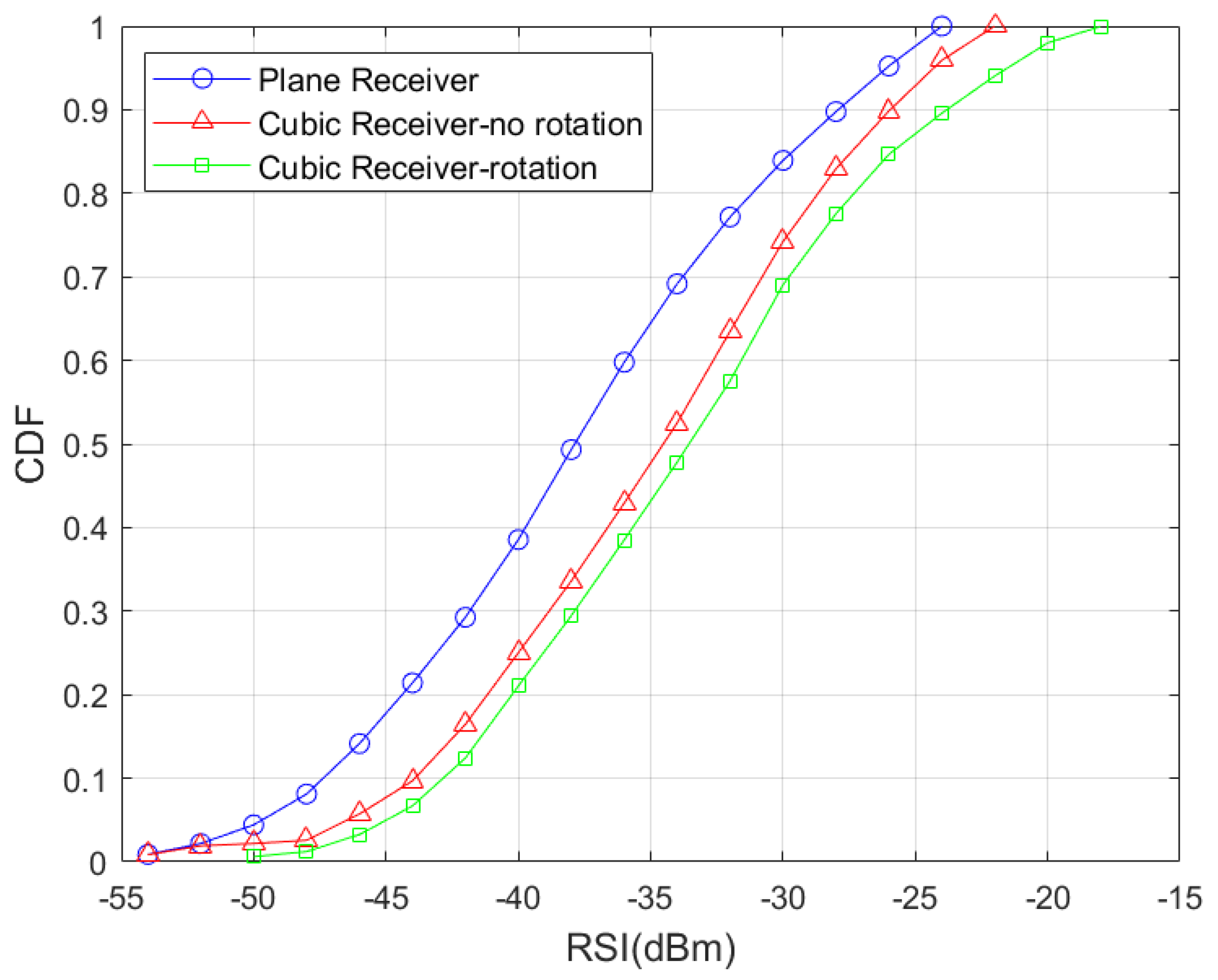
4.1. Cumulative Distribution Function (CDF) of RSI for Different Types of Receivers

Figure 6 and Figure 7 show the CDF of RSI for a plane receiver, a non-rotating cubic receiver, and an optimally rotated angle cubic receiver at each location within LED coverage when the half power angle is 30 and 60 . It can be seen from the simulation that, for the case Φ 1 / 2 = 30 , the probability that the RSIs of the rotating cubic receiver, the non-rotating cubic receiver, and the plane receiver are greater than −40 dBm are 80 % , 75 % and 60 % , respectively. For the case Φ 1 / 2 = 60 , the probability that the RSIs of the rotating cubic receiver, the non-rotating cubic receiver, and the plane receiver more than −40 dBm are 50 % , 30 % and 18 % , respectively. Additionally, the maximum RSI value of the rotating cubic receiver is larger than that of the other two receivers. To sum up, the cubic receiver can enhance the quality of the received signal, and the existence of the rotation angles can further improve the communication performance, which is conducive to efficient handover.

4.2. Handover Probabilities for Different Initial Positions

In Figure 8, we present the probability of handover in cases where the user is in a different initial position. According to the difference between the RSI of L A P 1 and L A P 2 during the movement of the rotating cubic receiver at the optimal angles from the initial position, we consider that the user will switch to the LAP with the stronger signal if the RSI from another LAP is greater than the RSI of the current LAP. Then, we can get the handover probability. As can be seen, the probability distribution is between 0.4 and 0.65.

4.3. Evaluation of Handover Performance

The receiver selects the LAP that provides the best signal quality for access to guarantee the robustness of the communication link. Due to the influence of the special structure and rotation angles from the cubic receiver, within a certain range, the RSI of L A P 2 is still higher than that of L A P 1 , so there is no need to handover in this case, as shown in Figure 9. R S I 2 R S I 1 > 0 means that terminal access L A P 2 can obtain a higher RSI at this location, and so on. Compared with the distance-based handover judgment criterion in traditional plane receivers, a better performance can be obtained according to the handover scheme presented in this paper, and the handover frequency will also be reduced to a certain extent.
In order to further reduce the amount of link handover and the reciprocation rate, we also added a hysteresis margin in the handover, and only when the received power of L A P 1 exceeds the hysteresis margin H (dB) of the received power of L A P 2 , is the handover started. According to Equation (16), we studied the effect of different hysteresis margins H on the handover when the receiver moves along the center line at a speed of v = 0.5 m / s .
P r 1 P r 2 10 H / 10 .
As shown in Figure 10, the ordinate represents the difference value between P r 1 P r 2 10 H / 10 , the value equaling 0 means that the switching condition is met. When the LEDs are separated by 4 m, for H = 0 dB, the terminal with a cubic receiver can move 1.5 m from the initial position (mentioned above) to meet the switching conditions. However, for the plane receiver, the switching condition is met when the terminal moves 1 m, that is, the handover occurs at midline. Similarly, for H = 3 dB, 6 dB, the terminal moves 1.8 m and 2.1 m, respectively, to meet the switching conditions. From this, we can see that a larger hysteresis margin is beneficial for reducing handover times and avoiding system overhead caused by frequent handovers. The relative received power algorithm with hysteresis can increase the robustness of the system and it reduces the number of handovers. Certainly, these also indicate that, for a cubic receiver, handover is not necessarily related to distance; the handover scheme that considers the structure, angle and position of the receiver together is more beneficial for improving system communication performance.

5. Conclusions

In this paper, we proposed a handover scheme for mobile users with a cubic receiver in a visible light communication system so that the users can connect to the access points which provide the best service. We then rotated the receiver at the optimal rotation angles to further improve the received signal quality. Through simulation results, it can be demonstrated that the cubic array receivers have better signal receiving ability, and the RSI is improved by 15– 20 % compared with plane receivers. Meanwhile, the handover scheme proposed in this paper jointly considered the structures, angles and positions of the cubic receivers, which is conducive to mobile terminals obtaining the best system communication performance. Based on this, the cubic receiver will have very high potential in industrial manufacturing scenarios; higher link quality and reliable connections can be achieved in VLC systems.

Author Contributions

Conceptualization, Y.S. and Y.Z. (Yijun Zhu); methodology, Y.S. and Y.Z. (Yanyu Zhang); software, Y.S.; validation, Y.S.; formal analysis, Y.S.; writing—original draft preparation, Y.S.; writing—review and editing, Y.Z. (Yanyu Zhang), Y.Z. (Yijun Zhu), X.D. and X.W. All authors have read and agreed to the published version of the manuscript.

Funding

This research paper was funded by the National Natural Science Foundation of China (NSFC) under Grant 61901524.

Acknowledgments

The authors would like to thank the anonymous reviewers for their valuable suggestions.

Conflicts of Interest

The authors declare no conflict of interest.

References

  1. Delgado, F.; Quintana, I.; Rufo, J.; Rabadan, J.; Quintana, C.; Perez-Jimenez, R. Design and implementation of an Ethernet-VLC interface for broadcast transmissions. IEEE Commun. Lett. 2010, 14, 1089–1091. [Google Scholar] [CrossRef]
  2. Lee, K.; Park, H.; Barry, J.R. Indoor channel characteristics for visible light communications. IEEE Commun. Lett. 2011, 15, 217–219. [Google Scholar] [CrossRef]
  3. Matheus, L.E.M.; Vieira, A.B.; Vieira, L.F.; Vieira, M.A.; Gnawali, O. Visible light communication: Concepts, applications and challenges. IEEE Commun. Surveys Tuts. 2019, 21, 3204–3237. [Google Scholar] [CrossRef]
  4. Wang, L.; Han, D.; Zhang, M.; Wang, D.; Zhang, Z. Deep reinforcement learning-based adaptive handover mechanism for VLC in a hybrid 6G network architecture. IEEE Access 2021, 9, 87241–87250. [Google Scholar] [CrossRef]
  5. Yan, K.; Li, Z.; Cheng, M.; Wu, H.C. QoS Analysis and Signal Characteristics for Short-Range Visible-Light Communications. IEEE Trans. Veh. Technol. 2021, 70, 6726–6734. [Google Scholar] [CrossRef]
  6. Gupta, A.; Fernando, X. Exploring secure visible light communication in next-generation (6G) internet-of-things. In Proceedings of the 2021 International Wireless Communications and Mobile Computing (IWCMC), Harbin City, China, 28 June–2 July 2021; pp. 2090–2097. [Google Scholar]
  7. Kamalakis, T.; Ghassemlooy, Z.; Zvanovec, S.; Alves, L.N. Analysis and simulation of a hybrid visible-light/infrared optical wireless network for IoT applications. J. Opt. Commun. Netw. 2022, 14, 69–78. [Google Scholar] [CrossRef]
  8. Teli, S.R.; Chvojka, P.; Vitek, S.; Zvanovec, S.; Perez-Jimenez, R.; Ghassemlooy, Z. A SIMO Hybrid Visible-Light Communication System for Optical IoT. IEEE Internet Things J. 2021, 9, 3548–3558. [Google Scholar] [CrossRef]
  9. Jarchlo, E.A.; Kouhini, S.M.; Doroud, H.; Eso, E.; Gawłowicz, P.; Zhang, M.; Siessegger, B.; Jung, M.; Ghassemlooy, Z.; Caire, G.; et al. Analyzing interface bonding schemes for VLC with mobility and shadowing. In Proceedings of the 2020 12th International Symposium on Communication Systems, Networks and Digital Signal Processing (CSNDSP), Porto, Portugal, 20–22 July 2020; pp. 1–5. [Google Scholar]
  10. Mayahi, M.; Costanzo, A.; Loscrí, V.; Vegni, A.M. An Interference to Noise Ratio Handover mechanism for Mobile Visible Light Communication Networks. In Proceedings of the 2022 13th International Symposium on Communication Systems, Networks and Digital Signal Processing (CSNDSP), Porto, Portugal, 20–22 July 2022; pp. 457–462. [Google Scholar]
  11. Hammouda, M.; Peissig, J.; Vegni, A.M. Design of a cognitive VLC network with illumination and handover requirements. In Proceedings of the 2017 IEEE International Conference on Communications Workshops (ICC Workshops), Paris, France, 21–25 May 2017; pp. 451–456. [Google Scholar]
  12. Raj, R.; Dixit, A. Outage analysis and reliability enhancement of hybrid VLC-RF networks using cooperative non-orthogonal multiple access. IEEE Trans. Netw. Service Manag. 2021, 18, 4685–4696. [Google Scholar] [CrossRef]
  13. Xiong, J.; Huang, Z.; Zhuang, K.; Ji, Y. A cooperative positioning with Kalman filters and handover mechanism for indoor microcellular visible light communication network. Opt. Rev. 2016, 23, 683–688. [Google Scholar] [CrossRef]
  14. Dinc, E.; Ergul, O.; Akan, O.B. Soft handover in OFDMA based visible light communication networks. In Proceedings of the 2015 IEEE 82nd Vehicular Technology Conference (VTC2015-Fall), Boston, MA, USA, 6–9 September 2015; pp. 1–5. [Google Scholar]
  15. Soltani, M.D.; Kazemi, H.; Safari, M.; Haas, H. Handover modeling for indoor Li-Fi cellular networks: The effects of receiver mobility and rotation. In Proceedings of the 2017 IEEE Wireless Communications and Networking Conference (WCNC), San Francisco, CA, USA, 19–22 March 2017; pp. 1–6. [Google Scholar]
  16. Mayahi, M.; Loscri, V.; Costanzo, A. INVISIBLE: Enhanced Handover technique for Vehicular Visible Light Networks. In Proceedings of the VTC 2022-Spring IEEE 95th Vehicular Technology Conference, Helsinki, Finland, 19–22 June 2022. [Google Scholar]
  17. Wang, S.; Tang, Y.; Du, J. Research on a New Type of Network Handover Strategy. In Proceedings of the 2021 International Conference on Electronic Information Engineering and Computer Science (EIECS), Changchun, China, 23–25 September 2021; pp. 93–96. [Google Scholar]
  18. Nabavi, P.; Yuksel, M. Comprehensive design and prototype of VLC receivers with large detection areas. J. Lightw. Technol. 2020, 38, 4187–4204. [Google Scholar] [CrossRef]
  19. Nuwanpriya, A.; Ho, S.W.; Chen, C.S. Indoor MIMO visible light communications: Novel angle diversity receivers for mobile users. IEEE J. Sel. Areas Commun. 2015, 33, 1780–1792. [Google Scholar] [CrossRef]
  20. Tian, Z.; Jiang, C.; Ni, S.; Wang, F.; Han, S.; You, S. Research on Hemispherical Receiver for Indoor MIMO Visible Light Communication. In Proceedings of the 2021 IEEE 6th Optoelectronics Global Conference (OGC), Shenzhen, China, 31 August– 3 September 2021; pp. 190–194. [Google Scholar]
  21. Soltani, M.D.; Purwita, A.A.; Tavakkolnia, I.; Haas, H.; Safari, M. Impact of device orientation on error performance of LiFi systems. IEEE Access 2019, 7, 41690–41701. [Google Scholar] [CrossRef]
  22. Du, X.X.; Mu, Y.; Ye, Z.W.; Zhu, Y.J. A passive target recognition method based on LED lighting for industrial internet of things. IEEE Photon. J. 2021, 13, 7300308. [Google Scholar] [CrossRef]
  23. Xu, W.; Wang, J.; Shen, H.; Zhang, H.; You, X. Indoor positioning for multiphotodiode device using visible-light communications. IEEE Photon. J. 2015, 8, 7900511. [Google Scholar] [CrossRef]
  24. Lin, X.; Zhang, L. Intelligent and practical deep learning aided positioning design for visible light communication receivers. IEEE Commun. Lett. 2019, 24, 577–580. [Google Scholar] [CrossRef]
  25. Haldurai, L.; Madhubala, T.; Rajalakshmi, R. A study on genetic algorithm and its applications. Int. J. Comput. Sci. Eng. 2016, 4, 139–143. [Google Scholar]
Figure 1. System configuration.
Electronics 12 00701 g001
Figure 2. The structure of receiver.
Electronics 12 00701 g002
Figure 3. Schematic diagram of handover.
Electronics 12 00701 g003
Figure 4. Algorithm iterative process.
Electronics 12 00701 g004
Figure 5. The flow diagram of handover.
Electronics 12 00701 g005
Figure 6. The CDF of RSI for Φ 1 / 2 = 30 .
Electronics 12 00701 g006
Figure 7. The CDF of RSI for Φ 1 / 2 = 60 .
Electronics 12 00701 g007
Figure 8. The handover probability for movement under every initial position.
Electronics 12 00701 g008
Figure 9. Distribution of the difference between RSI2 and RSI1.
Electronics 12 00701 g009
Figure 10. Influence of hysteresis margin on handover at different LED intervals.
Electronics 12 00701 g010
Table 1. Simulation Parameters.
ParameterSymbolValue
Transmit power P t 20 W
Half power angle of LED Φ 1 / 2 30 , 60
Height of LAPH3 m
PD field of view Ψ 60
Effective receiving area of PDA 1 cm 2
Disclaimer/Publisher’s Note: The statements, opinions and data contained in all publications are solely those of the individual author(s) and contributor(s) and not of MDPI and/or the editor(s). MDPI and/or the editor(s) disclaim responsibility for any injury to people or property resulting from any ideas, methods, instructions or products referred to in the content.

