1. Introduction
Building an optical communication network using two optical sources, despite the difference in their optical wave behavior, may result in the construction of a network that can provide reliable services at a reasonable cost. Recent research has focused on the latest technology that can provide quality of service (QoS) at an affordable cost. For this reason, bandwidth-starving applications increase exponentially. To provide increased-bandwidth connections in both metropolitan area networks (MANs) and local area networks (LANs), the optical communication system is of great importance, where a large number of users in a comparatively small area occasionally need to connect with other users in the network at data rates of Gbit/s [
1,
2].
The most important necessity of LAN is to permit users to have easy and fast network access. The optical code division multiple access (OCDMA) technique acts as a powerful candidate for LANs. OCDMA is a multi-access system developed and designed in such a way that a distinct code is allocated to each user. The user identifies the matched code to identify the required information from the concurrent users [
1,
2].
The spectral amplitude coding (SAC) OCDMA system has gained popularity since multiple access interference (MAI) was suppressed using spectral coding [
3]. However, as long as the number of subscribers increases, the MAI increases, resulting in increased bit error rate (BER) values which eventually limits the network capacity. There are a large number of codes available for the SAC–OCDMA system, and the interested reader may refer to references [
4,
5,
6,
7,
8,
9,
10,
11].
The SAC–OCDMA code system uses low-priced broadband incoherent sources such as amplified spontaneous emission (ASE) and light-emitting diodes (LEDs). These sources are matched with SAC–OCDMA operation by nature, and it must be realistic when implemented commercially. Signature code patterns can be easily achieved by chipping the frequency spectrum via different kinds of optical filters. Additionally, using LED sources has advantages such as a simple and easy implementation and large bandwidth [
12]. However, when high transmission rates are desired, the use of LED sources imposes bandwidth limitation constraints on the system and reduces spectrum efficiency because their intensity noise limits system performance [
13].
Experimental and simulation work published on SAC-based systems mostly employs incoherent broadband sources. The main issue with such sources is that they provide low data rates when long-distance communication is involved due to intensity noise impact [
14]. Thus, coherent light sources must be incorporated in place of LEDs for long-distance communication due to their increased transmission capabilities in terms of data transmission rates and fiber distance compared to conventional optical sources [
15]. At the same time, the drawback of such a system is that one laser for each code weight per user is required, eventually affecting the cost of the system and increasing complexity [
16].
Moreover, the choice of a laser diode over an LED as a light source in a fiber optical medium depends on a number of factors such as the target application, related system performance, and reliability requirements of the overall solution being designed [
17].
The first-time application of a multi-laser source for the OCDMA system is introduced and its performance comparison is made with two different optical sources (a broadband erbium-doped fiber source and a multi-array source) in terms of BER and data rates [
18]. The multi-array source outperformed the incoherent source for the chosen design parameters. The use of a multi-array laser source in the SAC system is introduced by considering different strategies such as coherent sources and multi-array laser sources with forwarding error correction (FEC). SAC system performance is checked in terms of transmission capacity and cost. Further, performance comparison and trade-off are made among these techniques [
19].
Performance analysis of an SAC system with a diagonal double weight (DDW) code in an FSO communication system is reported in [
20]. A continuous-wave (CW) laser source with a DDW code was used, and performance was analyzed under rain and haze conditions. The results indicate that a multi-array source in combination with a DDW code provides acceptable performance even when transmitted power values are low.
Furthermore, to bypass the shortcomings of incoherent sources, previous studies suggested using multi-wavelength laser sources (laser arrays) to achieve higher performance without examining the attainable performance. Such an analysis is essential because lasers of the same wavelength support higher data rates. Indeed, a coherent single-wavelength light source that can generate a huge number of wavelengths is a cost-effective approach [
21]. Hence, the use of optical sources is very important because it trades off all the advantages of both coherent and incoherent sources [
22]. So, using both coherent and incoherent sources together as we introduce a CCIS technique in this paper will achieve the advantages of both LED and CW laser sources, where a high number of users is achieved in comparison to an LED source with a low BER and a higher data rate [
23]. In this paper, for the first time according to our knowledge, an FSO communication system based on the use of CCIS with an SAC–OCDMA system using an FRS code is proposed. Additionally, different weather conditions such as different haze levels (low, medium, and heavy) and different fog levels (low, medium, and heavy) are implemented. Moreover, the feasibility of using the CCIS technique in aerial altitude platform system (AAPS) applications that are based on the FRS code is discussed. The performance is investigated in terms of bit error rate (BER), fiber length, FSO propagation range, quality factor (Q-factor), and eye diagram.
Therefore, the main contribution of our proposal is as follows:
Provision of an affordable solution for future communication system that is neither costly nor complicated;
Application of the CCIS technique for codes having a fixed cross-correlation of unity (CC = 1) such as the DPS code;
Application of the CCIS technique in a free space optics (FSO) system by investigating different weather conditions;
Application of the CCIS technique in a sky mesh network using the aerial altitude platform system (AAPS).
This paper is structured in as follows.
Section 2 deals with the principle of CCIS operation based on SAC–OCDMA systems.
Section 3 discusses the feasibility of applying CCIS in different SAC–OCDMA codes. CCIS designs for three coherent source configurations are presented along with their performance analysis with FRS codes in
Section 4 under an FSO channel. The application of CCIS design for an AAPS in a sky mesh network under an SAC–OCDMA system is given in
Section 5. The conclusion is given in
Section 6.
2. Principle of CCIS Operation Based on SAC–OCDMA Systems
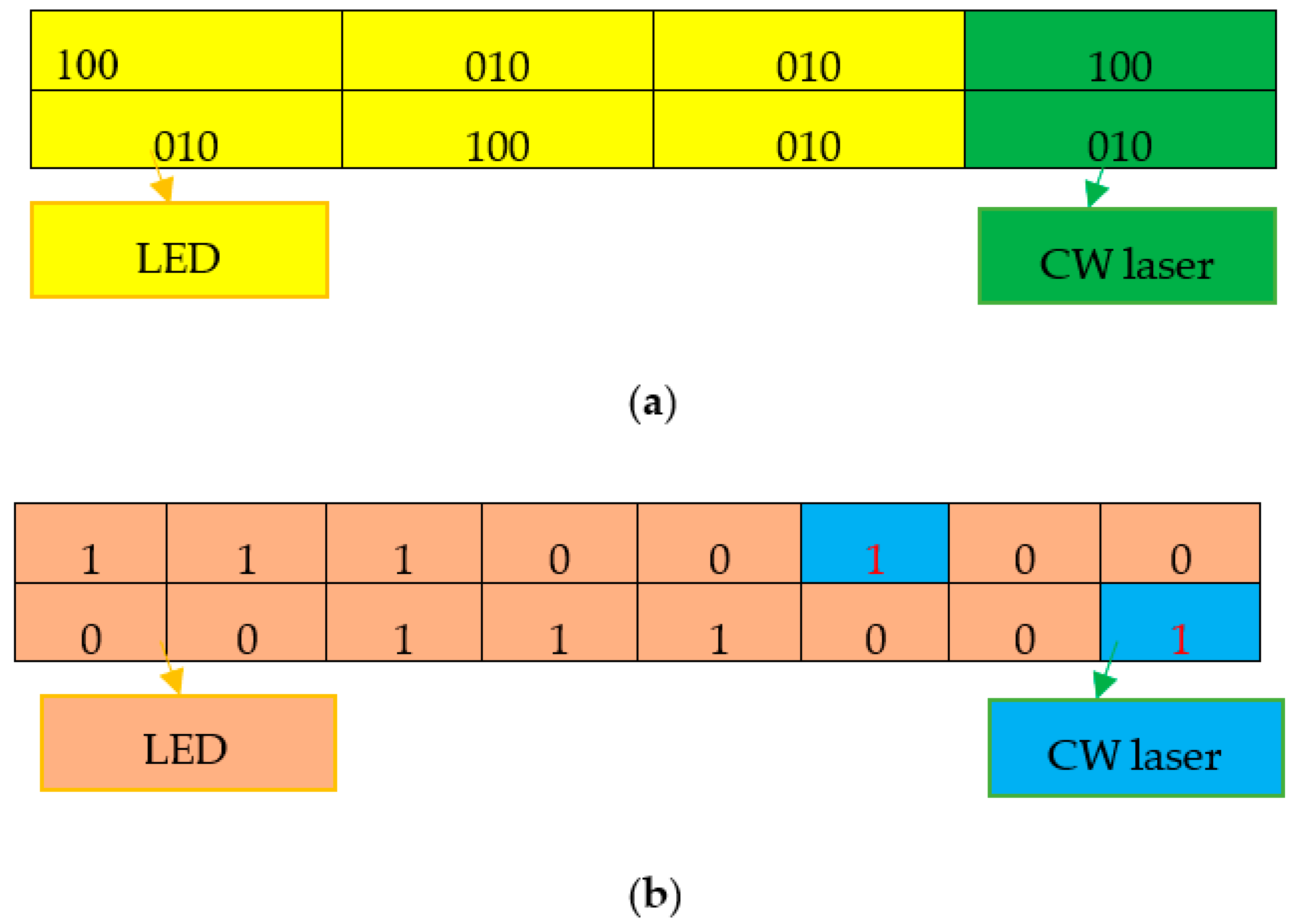
CCIS is a technique in which a combination of a CW laser (coherent source) and an LED (incoherent source) is adopted together for one user. The signal originating from the CW laser always passes without a subtraction process, while the sliced LED signals are involved in the subtraction process where the MAI is targeted. In
Figure 1a, where the DPS code is used, the yellow block of the DPS code is encoded via a sliced LED, which circulated to the subtraction operation, whereas the green color block is encoded via the laser with no overlapping. Likewise, in
Figure 1b, where the FRS code is used, the output is ultimately decoded with the desired shape. The single photodiode (SPD) detection technique is investigated in this work for a trade-off between the LED and the CW laser.
The wavelength spectrum in the case of SAC is divided into bins similar to the spectral code allocated to certain subscribers [
24]. The data in a CCIS design is not distributed across the LED and laser wavelengths. In fact, the split LED spectrum and laser carry the same data bits and are used as a code sequence. For example, the pseudorandom binary sequence (PRBS) of user#1 is coded with the DPS code sequence “100010010100” [
11] via the on–off keying (OOK) modulation technique. In this modulation, each “1” of information is mapped accordingly to a specific code sequence.
Figure 2 depicts the data distribution between the LED and laser wavelengths. For example, if the data sequence is “PRBS = 1001”, then the coded data for the same sequence using the CCIS design will be “100010 01010000100010 010100”.
The DPS code has a feature of chip arrangements that are separated from one another at a regular distance. This feature, fortunately, matches with the CCIS design in which two blocks are proposed; the first block contains p that represents the number of bits “1s” having a length of p2 which is encoded via the LED and the remaining block comprises only bit “1” having a length of p that is assigned to the laser, as shown in
Figure 1. The ultimate goal of the receiving section is to detect and recover the desired spectrum with a high autocorrelation and a low cross-correlation between the desired and interfering subscribers.
Figure 3 shows a block diagram of the CCIS network where the incoming signal from the laser always passes without a subtraction process. In contrast, the signal coming from a sliced LED always needs subtraction since an MAI always resides in the LED portion. The detection arrangement at the receiving end is also configured to recover the entire encoded spectrum (containing both the LED and laser diode spectrums) in an attempt to yield maximum autocorrelation (equal to the weight of the code) and minimum cross-correlation. The output of the detector arrangement is sent to a photodiode for optical/electrical conversion and decision-making circuitry, respectively. The decision-making circuit computes the probability density function (PDF) of the received current with a certain threshold value to determine binary ‘1’ or ‘0’. If the system encounters nonlinearities, such as four-wave mixing (FWM), dispersion, and cross-phase modulation (XPM), then an optical source that trades off all the advantages of coherent and incoherent sources is utilized. The mechanism could be achieved by merging both the coherent and incoherent sources all at once.
3. Feasibility of Applying CCIS in Different SAC–OCDMA Codes
In SAC systems, utilizing a novel technology with a reliable quality of service (QoS) and fair economic feasibility is an attractive idea. Additionally, in recent years, attention has been paid to extended bandwidth requirements to fulfil all bandwidth-starving applications. As a future technology, CCIS design implementation could be considered feasible. Low-priced broadband sources that are incoherent (i.e., ASE and LEDs) with the incorporation of simple optical filters for wavelength assignment make them applicable for SAC [
24,
25]. Similarly, the power output of a CW laser does not change over an averaged period, and large frequency power variations with minimum effect in any class of applications tend to make it an efficient source but a costly option [
23]. Considering all the benefits of LED and laser sources, the CCIS design is proposed, which trades off all the advantages of incoherent and coherent sources. Further, to reliably design OCDMA networks, particularly for long-haul communication where non-linearities (XPM, FWM) and dispersion exist, CCIS design feasibility is checked, which is obtained by simultaneously combining both incoherent and coherent sources.
Table 1 summarizes the feasibility of applying CCIS in SAC for different family codes having different values of cross-correlation (CC) such as Hadamard [
8], multi-service (MS) [
10], random diagonal (RD) [
13], FRS [
7], diagonal Eigen value unity (DEU) [
9], enhanced multi-diagonal (EMD) [
18], modified quadratic congruence (MQC) [
4], modified frequency hopping (MFH) [
4], and zero vectors combinatorial (ZVC) [
22].
4. Performance when Using CCIS in FSO Applications
Figure 4 shows the block diagram of an FSO system based on CCIS–OCDMA architecture. This scheme of the recommended SAC–OCDMA configuration employs FRS coding with three simultaneous clients. In FSO, a variety of link lengths are examined at various visibilities. The encoder-containing transmitter is made up of a CCIS as a source that provides an OCDMA encoding process. To create the information signals, a pseudo-random bit generator (PRBG) and non-return-to-zero (NRZ) coding are employed in conjunction with an external Mach Zehnder modulator. Finally, an ideal multiplexer is employed to combine the signals. The FSO channel mixes the signals that are propagating. The receiver houses the decoding process, which includes FBGs and photodetectors. FBGs with the same bandwidth but different Bragg wavelengths are employed for signal decoding depending on the detecting strategies used. The photodiode is used to convert optical to electrical signals. A Bessel LPF with an order of four is used to cancel the interference, noise, and components.
The proposed models are simulated using Optisystem software version 13 with parameters values given in
Table 2 [
25,
26].
The proposed FSO model that uses CCIS at the transmitter is simulated using the parameters given in
Table 2 using Optisystem software [
23,
24,
25].
Figure 5 shows the BER versus the variation of the FSO range under clear weather conditions. As the range increases, the BER increases for all optical sources. The figure reveals an acceptable BER of the FRS code (CW laser) at an error free transmission code which is lower than that for LED sources and CCIS when similar parameters were applied. For comparison, at an FSO transmission distance of 9 km, the values of BERs are 1.86 ×
, 1.96 ×
and 1.83 ×
for the laser, CCIS, and LED, respectively.
The eye diagram at an FSO range of 9 km is displayed in
Figure 6. It shows a larger eye opening which assures the successful transmission of the information data at the receiver. Additionally, the effect of different haze levels on the performance of the proposed FSO model that uses CCIS is studied. As low haze weather causes a lower attenuation coefficient (1.537 dB/km) compared to that of medium (4.285 dB/km) and heavy (10.115 dB/km) hazes weather conditions, the information signal can propagate a longer range under it.
Figure 7 shows the BER versus different ranges for our proposed model under different haze levels, and one can observe that at a BER of approximately
, the FSO ranges are 3.7 km under low haze, 2.5 km under moderate haze, and 1.5 km under heavy haze. So, as the FSO and the haze level range increase, the BER increases.
Figure 8 depicts the Q-factor versus the range under different haze levels for the proposed model. As the level of haze become lighter, the propagation range and the Q-factor increase. At a Q-factor of
4.5, the FSO ranges under low haze, moderate haze, and heavy haze are, respectively, 3.7 km, 2.5 km, and 1.5 km.
Figure 9 shows the eye diagrams that obtained from the simulation of our proposed model at an FSO range of 3.7 km under low haze, 2.5 km under moderate haze, and 1.5 km under heavy haze. The wider eye opening shows the good reception for the information signal at the receiver.
Table 3 summarizes the log(BER) and Q-factor values for our suggested model under low haze at 3.7 km, medium haze at 2.5 km, and heavy haze at 1.5 km.
Fog, which is an atmospheric phenomenon that occurs due to suspended smoke particles in the atmosphere, causes a degradation in the information signal during propagation in the FSO channel. Dense fog causes a larger attenuation coefficient than medium fog and low fog. The attenuation coefficients are 9 dB/km for light fog, 16 dB/km for moderate fog, and 22 dB/km for heavy fog. Thus, the performance of our proposed model under different levels of fog conditions are investigated.
Figure 10 and
Figure 11 show log (BER) and Q-factor, respectively, versus different propagation ranges. As the FSO range increases and the level of fog becomes heavier, the BER increases and the Q-factor decreases. The longer range of 1.6 km is achieved under light fog which is decreased to 1 km under medium fog and further decreased to 0.8 km under heavy fog.
Figure 12 shows the eye diagrams that obtained from the simulation of our proposed model at an FSO range of 3.7 km under low haze, 2.5 km under moderate haze, and 1.5 km under heavy haze. The wider eye opening shows the good reception for the information signal at the receiver.
Table 4 summarizes the log(BER) and Q-factor values for our suggested model under low haze at 1.6 km, medium fog at 1 km, and heavy fog at 0.8 km.
5. Performance when Using CCIS in AAPS Sky Mesh Network Applications
Recently, FSO systems have played a noteworthy role in rustic and catastrophe-prone circumstances. They provide definitive data to groups of people and organizations in the aftermath of natural or man-made disasters. A disrupted communications foundation necessitates quick arrangement communication systems to carry out critical assistance; however, communication towers are costly for rural, remote, and geographically challenged areas. Additionally, satellite platforms provide high infrastructure, which increases the costs for each subscriber. The need for a foundation in rural zones and high establishment costs compared to urban regions are the two significant obstacles in building a remote area that would cater to the needs of the local community, particularly when other modes of communication are disturbed [
26].
Fiber-wireless (FiWi) communication services are usually provided by terrestrial and satellite systems. The demand for large capacity remote administration is growing, particularly for “last mile” conveyance [
21]. Existing methods of telecommunication using satellites and telecommunication towers have several limitations. In isolated areas, the performance of communication systems can be enhanced by utilizing an aerial altitude platform system (AAPS), due to the fact that conventional approaches fail to support full access to the data link in rural and isolated areas [
21]. Therefore, the AAPS communication system in rural and remote areas is suggested. This technique causes an acceleration in the adoption of the internet and telecommunications by rural communities. The achievability of the framework will be set up through tests and a field trial. The large-scale arrangement of the created framework can play a significant role in bridging the gap between distant communities that are beyond the reach of current telecommunication. The system diagram of the AAPS in a sky mesh network is shown in
Figure 13. The method used for data transmission between the primary part, sky station 1 (SS1), and the base, which, in turn, transmits signals to the second node, sky station 2 (SS2), depends on radio frequency (RF) cycles. In the RF cycle, SS1 is connected to the ground station (GS) via IEEE 802.11a, while in the second phase, SS1 is linked to SS2 through RF, and all nodes provide coverage to the ground by utilizing the IEEE 802.11 b/g standard.
In this work, we suggest a new method for signal transmission between the sky stations depending on the optical cycle. This method connects the GS to SS1 through a fiber optic cable while SS1 is connected to SS2 via the FSO channel. To be able to examine the performance of FSO, some parameters must be taken into consideration. These parameters can be classified into two categories. The first category considers the internal parameter related to the design of the FSO communication system as transmitted power, as well as bandwidth, beam divergence angle, and BER on the receiver side. However, the second category depends on an external limitation, such as weather conditions, which causes attenuation and may lead to link failure.
The relation between the received and transmitted power can be expressed as [
26]
where
,
, a
,
,
, and
R indicates received power, transmitted power, received aperture diameter, transmitted aperture diameter, beam divergence, and link range, respectively, while
refers to the atmospheric attenuation.
The bidirectional FSO transmission and receiving communication system needs a line of sight for both the transmitter and receiver sides. Therefore, a wireless optical beam is used to establish a data bridge between the two nodes (SS1 and SS2). The performance in terms of eye pattern and BER of the inter-platform communication system is conducted by making a simulation for the proposed model given in
Figure 10.
The design represents a transmitter side in the SS of SS1, while the receiver is shown in SS2. The transmission and channel parts, as shown in
Figure 14a, include the following:
A PRBG;
NRZ pulse generator for information signal;
Optical source (LED, CW laser, and CCIS) to make the encoder of SAC–OCDMA
using FRS codes;
An MZM modulator;
An FSO channel.
The avalanche photodiode (APD) is used in the complementary subtraction detection technique and the LPF is used in the receiver part of SS2 propagation, as shown in
Figure 14b. The parameters of the FSO system are set according to typical industry values in order to simulate a real-world environment as closely as possible.
Table 5 indicates the parameters that are used in the FSO channel [
25,
26].
Figure 15 depicts the eye openings for CW laser, LED optical sources, and CCIS-based AAPS-OCDMA systems at 1.25 Gbps data rate with a total of 16 subscribers at 0 dBm received power. The results show that the eye-opening in the CCIS design is quite wide compared to the pure LED-based system, and the eye-opening is less with pure laser. Also, the distance is the main factor that limits performance regardless of the type of optical source. The maximum distance that the proposed system can propagate with BER less than is 6, 38, and 60 km, respectively, when LED, CCIS, and CW laser sources are used. The simulation experiments showed that the CCIS design significantly improves system performance because the combined light source (CW laser + LED) increases the effective transmission power of the first system in proportion to the angle of permittivity of the laser beam received. The possibility of using the FSO system in the sky mesh network based on the CCIS–OCDMA system leads us to our conclusion.
6. Conclusions
A cost-effective solution for SAC–OCDMA technology that provides a solid platform for multiple access networks named CCIS is described. CCIS design combines a CW laser (coherent source) with an LED (incoherent source) and improves system performance considerably. CCIS design trades off low-cost LED sources with a low output power and expensive CW laser sources with a high output power. Furthermore, the study conducted and validated performance analysis on the CW laser, CCIS, and LED optical sources in both FSO and AAPS systems. Further investigation is made in the sky wave communication, which showed the possibility of using the FSO system in the sky mesh network based on the CCIS–OCDMA system. As means of comparison at an FSO transmission distance of 9 km, the values of BER are 1.86 × , 1.96 × , and 1.83 × for the laser, CCIS, and LED, respectively. This is because low haze weather causes a lower attenuation coefficient (1.537 dB/km) compared to that of medium (4.285 dB/km) and heavy (10.115 dB/km) hazes weather conditions, so the information signal can propagate a longer range under it. The FSO ranges under low haze, moderate haze, and heavy haze are 3.7 km, 2.5 km, and 1.5 km, respectively. At 1.25 Gbps data rate with a total of 16 subscribers at 0 dBm received power, the AAPS–OCDMA system for the CW laser, LED optical sources, and CCIS showed an acceptable BER of 3.3 × 10⁻¹⁴, 4.4 × 10⁻¹³, and 1.5 × 10⁻¹², respectively.
It is concluded that, as the FSO range and the haze level increase, the BER also increases. Additionally, distance is the main factor that limits performance, regardless of the type of optical source being used. In conclusion, a reasonable and dependable solution for future optical communication systems might be created by combining technologies effectively.

 ,
, 


