Article

Side-Milling-Force Model Considering Tool Runout and Workpiece Deformation

1
School of Mechanical Engineering, Liaoning Technical University, Fuxin 123000, China
2
School of Mechanical Engineering, Liaoning Petrochemical University, Fushun 113001, China
3
School of Mechanical Engineering, Lancaster University, Lancaster LA1 4YW, UK
*
Author to whom correspondence should be addressed.
Electronics 2023, 12(4), 968; https://doi.org/10.3390/electronics12040968
Submission received: 2 January 2023 / Revised: 5 February 2023 / Accepted: 13 February 2023 / Published: 15 February 2023
(This article belongs to the Section Computer Science & Engineering)

Abstract

:
With the development of Industry 4.0, hard-cut materials such as titanium alloys have been widely used in the aerospace industry. However, due to the poor rigidity of titanium alloy parts, deformation and vibration easily occur during the cutting process, which affects the accuracy, surface quality and efficiency of part machining. Therefore, in this paper, tool runout and workpiece deformation are introduced into the milling process of flat-end mills. Based on the tool’s hypocycloid motion, a geometric parameter model of the milling process is established, and the undeformed cutting thickness model is obtained considering the tool runout and workpiece deformation. Finally, the milling force model for side-milling titanium alloy thin-walled parts was established. The accuracy of the force model is verified through experiments. The error of the proposed model is far less than that of the traditional basic method. The maximum error of the traditional basic method is 87.09%. However, the maximum error of the proposed model is only 66.54%. The results show that the proposed force model considering tool runout and workpiece deformation can provide more accurate milling force prediction.

1. Introduction

Milling force will affect the milling heat, tool wear, surface quality and other aspects, and ultimately will affect the quality of products. Therefore, the milling force will be the basis for studying other aspects of milling processing. In milling, undeformed cutting thickness will be the cause of change; therefore, undeformed cutting thickness models will be the basis for studying the milling force model. Up to now, the research on undeformed cutting thickness models mainly adopts classical and tool hypocycloid motion undeformed cutting thickness models. Classical models of undeformed cutting thickness will have long occupied major positions in the study of macroscopic milling. The classic undeformed cutting thickness will describe the motion of the tool as a cycloidal motion because the radius of the knife tooth will be much greater than the feed amount per tooth. The undeformed cutting thickness will be expressed by the following formula:
h δ = f z   sin ( δ )
Among them, fz is the feed per tooth, and δ is the tool contact angle.
Scholars conducted a large amount of research on the influencing factors of the classical undeformed cutting thickness model, including tool eccentricity [1], tool axis inclination angle, tool runout [2], tool deflection deformation, tool bottom effect, tool wear [3,4], material properties and so on. When establishing the model of undeformed cutting thickness, Armarego et al. [5] studied the influence of tool eccentricity on undeformed cutting thickness, Liang et al. [6] studied the influence of feed per tooth on tool eccentricity, Shi [7] considered the relationship between tool eccentricity and tool rotation angle, and Cao et al. [8,9] considered the influence of the curvature radius and the cutting-force coefficient on the undeformed cutting thickness model of the ball-end milling cutter. Wan Min [10] of Northwestern Polytechnical University proposed an undeformed cutting thickness model considering tool runout, and established a tool runout recognition model. On this basis, Wan Min [11] also extended the tool runout recognition model, compared and analyzed the influence of three tool runout models on milling force, and calculated the new cutting-force coefficient. Desai et al. [12] introduced tool runout into the milling of complex curved workpieces. Zhu et al. [13] set up five-axis machining of complex surfaces considering tool runout.
Most of the above literature studies the tool and workpiece as rigid bodies. To meet the market demand, a large number of difficult-to-cut and thin-walled parts such as titanium alloy thin-walled parts are used in the aerospace industry. In the processing of such parts, due to its low stiffness, easy deformation, tough cutting and other characteristics, the workpiece needs to be treated as a flexible body. Wan Min [14] found the undeformed cutting thickness model of titanium alloy thin-walled parts and considered the deformation of the tool-workpiece system. Ratchev [15] found a finite element model of thin-walled parts to simulate and predict the deformation of the workpiece during the cutting process. On this basis, a cutting-force model is established. Then, Ratchev [16] combined the plastic layer model and the finite element model to predict the deformation of the workpiece and verified the average force obtained experimentally.
In addition to the above classical undeformed cutting thickness research, the researchers [17,18] also use the tool subcycloid motion to establish the undeformed cutting thickness model. Since the subcycloid motion of the tool is closer to the real motion trajectory of the tooth point, a more accurate milling force model can be established by the undeformed cutting thickness based on the subcycloid motion of the tool.
In the case of known undeformed cutting thickness, there are many ways to establish a milling force model. In summary, the cutting-force model is usually divided into a linear cutting-force model, an exponential instantaneous cutting-force model, a polynomial fitting cutting-force model, an exponential average cutting-force model and so on. Kaymakci et al. [19] found a general cutting-force model for inlaid milling cutters, which takes into account the factors such as tool bounce, variable pitch and screw. Safari et al. [20] conducted milling experiments on coated and uncoated inserts and found that the cutting force is inversely proportional to the cutting speed. Azeem et al. [21] proposed a cutting-force model for multi-axis ball-end milling. Ji et al. [22] used the three-dimensional finite element method to simulate the cutting force and discussed the influence of various processing parameters on the milling force.
In the cutting-force model, thin-walled parts were also often used as research objects, and the cutting tool was generally a helical milling cutter. Altintas et al. [23] established a general mechanical model of helical tooth milling for the influence of helical angle on milling mechanics. Izamshah et al. [24] proposed the influence of spiral angles on deflections by cutting thin-walled parts. Hadzley et al. [25] studied the influence of different helix angles on the surface error of thin-walled parts milling through experiments and finally pointed out that the helix angle of 35° reached the minimum error. Aiming at the deflection and deformation of thin-walled parts, Arnaud et al. [26] establish a flexible cutting-force model by using time domain simulation technology, and discuss the influence of back angle on plowing. Altintas et al. [27] established a flexible cutting-force model based on a comprehensive consideration of factors such as the spiral effect, variable pitch, tool runout and workpiece flexibility.
To sum up, it is very important to establish a cutting-force model that fits the actual machining. The accurate and efficient cutting-force model can not only guide production but also provide theoretical support for the prediction of tool residual life, milling stability analysis and other processing problems, and provide ideas on the reliability experiment of the key functional components of the machining center [28,29]. At present, scholars mainly focus on the influence of various factors on the accuracy of the cutting-force model [30,31,32]. Undoubtedly, workpiece deformation and tool runout are common phenomena in actual production. However, few of them are considered comprehensively when establishing cutting-force models. Therefore, the comprehensive effects of tool runout and workpiece deformation are considered simultaneously in this paper. Based on the undeformed chip thickness model, the tool runout term is introduced, and the milling force model considering tool runout and workpiece deformation is finally established. Based on the theoretical model of tool runout and workpiece deformation, the undeformed chip thickness model considering tool runout and workpiece deformation is established. Then, the milling force model of titanium alloy thin-walled parts is established. Finally, the cutting-force model is verified and analyzed by experiments.
Hence, the milling force model considering tool runout and workpiece deformation is proposed in the paper. The remaining section of this paper is organized as follows: Section 2 describes the theoretical basis of runout and workpiece deformation. At the same time, the undeformed cutting thickness model is established in this section. In Section 3, the novel approach to constructing the milling force model for titanium alloy thin-walled parts based on runout and workpiece deformation is described. In Section 4, the milling force coefficients are identified using the average milling force method. In order to verify the effectiveness of the method proposed in this paper, Section 5 presents the experimental component including setting up the experimental platform and discussing the results. Some conclusions are obtained in Section 6. The flow chart of the full-text method is shown in Figure 1, as follows:

2. Theoretical Model

2.1. Meaning of Tool Runout and Definition of Parameters

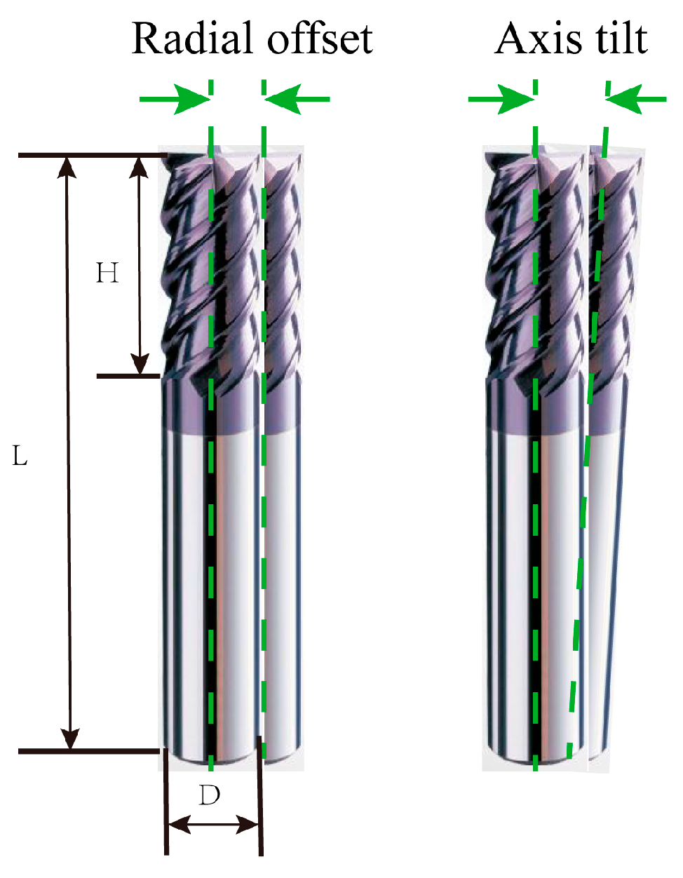
The manufacturing error and clamping error of the tool and spindle components cause the drift and eccentricity between the tool axis and the ideal rotation axis of the spindle, the wear of the tool during the machining process, and the specific machining process and tooling, which may cause the CNC milling machine tool to jump during the machining process. Tool runout is divided into radial offset and axis tilt, as shown in Figure 2.
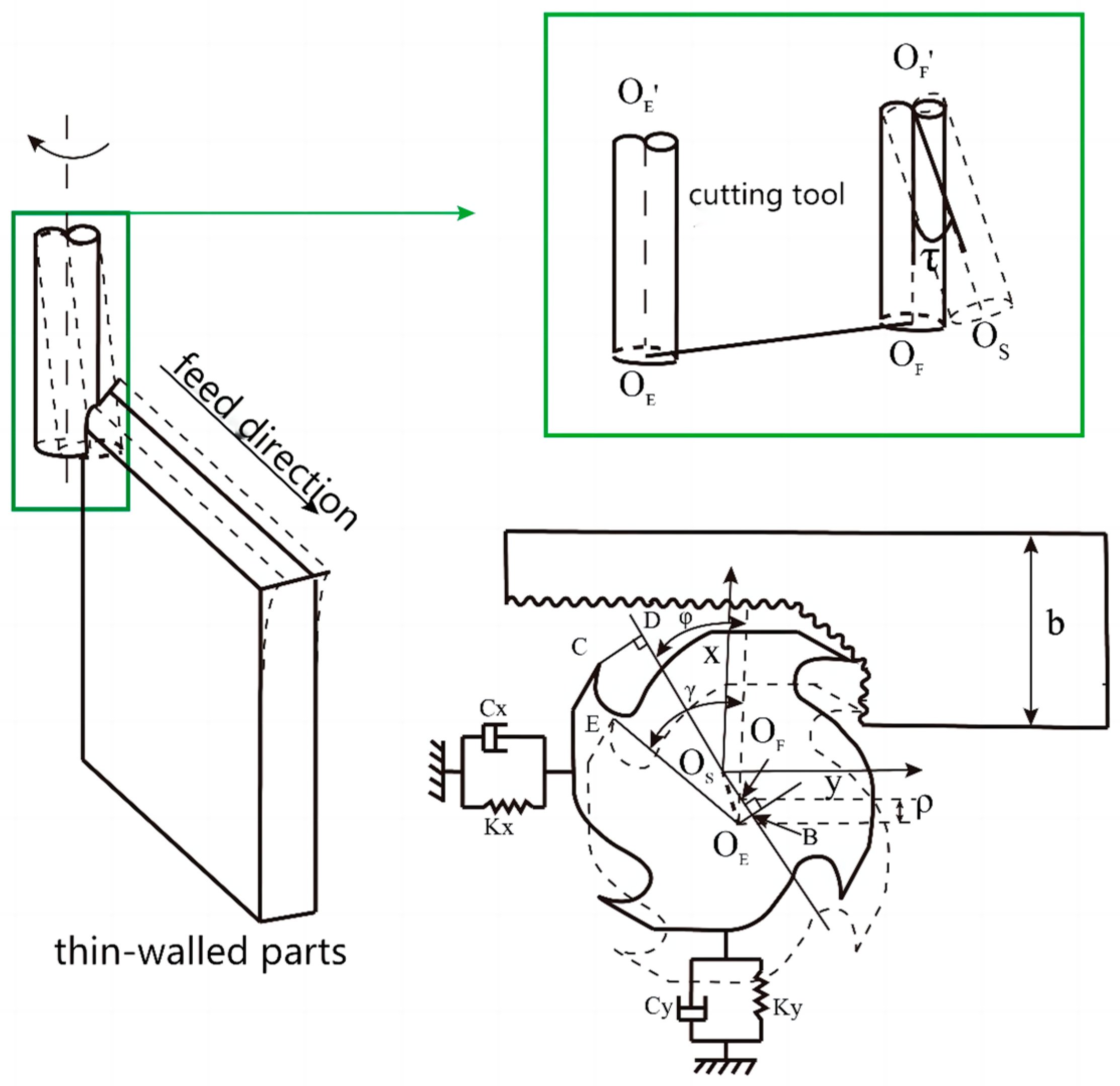
In the cutting process, the tool coordinate axis, as shown in Figure 3, the coordinate axis after radial runout and the coordinate axis after axial tilt are established. Starting from the real tool runout situation and considering the radial offset and axis tilt of the tool axis, the following four parameters are defined for the tool runout of the tool-workpiece cutting system:
Eccentric distance ρ: O E′O E is the cutter center line not considering the tool beating value, O F′ O F is the cutter center line considering the tool radial beating, and O F′O S is the cutter center line considering both radial beating and tool axial tilt. The tool beat eccentricity distance ρ is the vertical distance between the two parallel milling lines O E′O E and O F′ O F.
Position angle of the eccentric γ: The position angle of the eccentric γ is the angle between the tool eccentric O E O F and the vector O F′A from the tool center to the first knife tooth (j = 0).
Tangleτ: The tool beating tilt angle is the clip angle between the tool axis O F′O S and the ideal tool axis O E′ O E.
Position angle of the tilt angle φ: The position angle of the tool beat tilt angle φ refers to the angle between the tool tilt direction BD and the tool radial offset direction O E O F.
Based on the above definition, consider that the actual cutting radius of the tool after the tool beating is [11]:
R i , j ( z ) = { ρ 2 + R 2 + L z 2 s i n 2 τ + 2 R ρ cos γ + ψ + 2 j π N + 2 L z s i n τ ( ρ c o s φ + R c o s ( φ ρ + ψ + 2 j π N ) ) } 1 / 2
L is the hanging length of the tool after installation. H is the length of the cutting edge. D is the radial of the cutter. Generally, in this model, ignoring the tilt angle τ and the tilt angle position angle φ can achieve better results in the cutting-force prediction, and also facilitate the experimental identification of tool beating. Therefore, only the two tool beating parameters of the eccentric ρ and eccentric position angle γ are considered in this paper.

2.2. Undeformed Cutting Thickness Model Considering Tool Runout and Workpiece Deformation

2.2.1. Geometric Parameter Definition of Milling Process

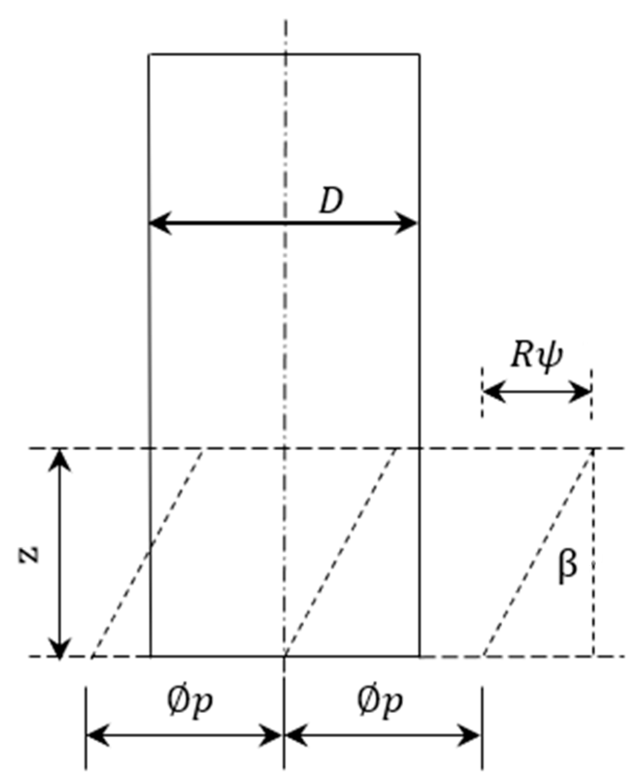
First, the tool coordinate system TCS (x, y, z) is established, as shown in Figure 4. The coordinate origin is the center of the tool bottom, the z-axis and the tool axis direction are consistent, and the x-axis is the tangent direction of the tool track curve at the cutting point. For the spiral angle of the spiral vertical milling cutter, the point on the cutting shaft will lag behind the end point of the tool, and the lag angle at the axial cutting depth (z) is
ψ = z t a n β R
where R is the milling cutter radius. The angular velocity of the spindle is ω (rad/s), t(s) is the cutting time, then the rotation angle of the first tooth φ ( t ) is
t = ω t
The contact angle δ j ( t ) of any point P (axial height z) on the jth cutter tooth can be calculated by
δ j t = t + ( j 1 ) p ψ
where p is the inter-tooth angle between each cutter tooth, defined as
p = 2 π N
where N is the number of milling cutter teeth.

2.2.2. Undeformed Cutting Thickness Model Considering Tool Runout and Workpiece Deformation

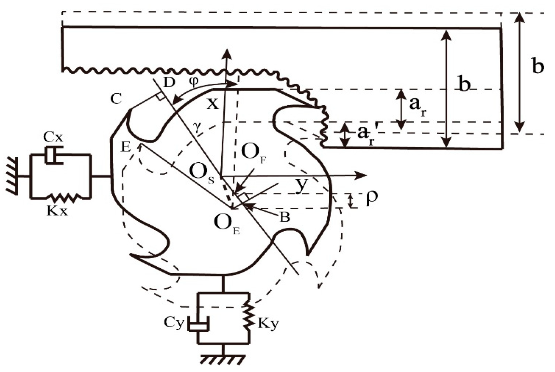
Due to the low stiffness of thin-walled parts, the workpiece is prone to elastic deformation during milling, as shown in Figure 5. The width of the workpiece is b, the real line represents the contour line of the workpiece that does not occur, and the radial cutting depth is a r . The imaginary line represents the contour line of the workpiece when the radial elastic deformation occurs, and the radial cutting depth is a r .
In the milling model in Figure 5, the workpiece has a large stiffness in the y direction, so only the deformation of the workpiece along the x direction is considered. Both the tool and the workpiece are regarded as non-rigid bodies. Due to the simultaneous radial offset and axis tilt in the tool runout, the actual cutting radius of the tool will change after the combined action. The workpiece displacement in the x direction will cause changes in the cutting thickness and contact angle:
δ j s t = c o s 1 R i , j z f t s i n δ j t Δ x R i , j z
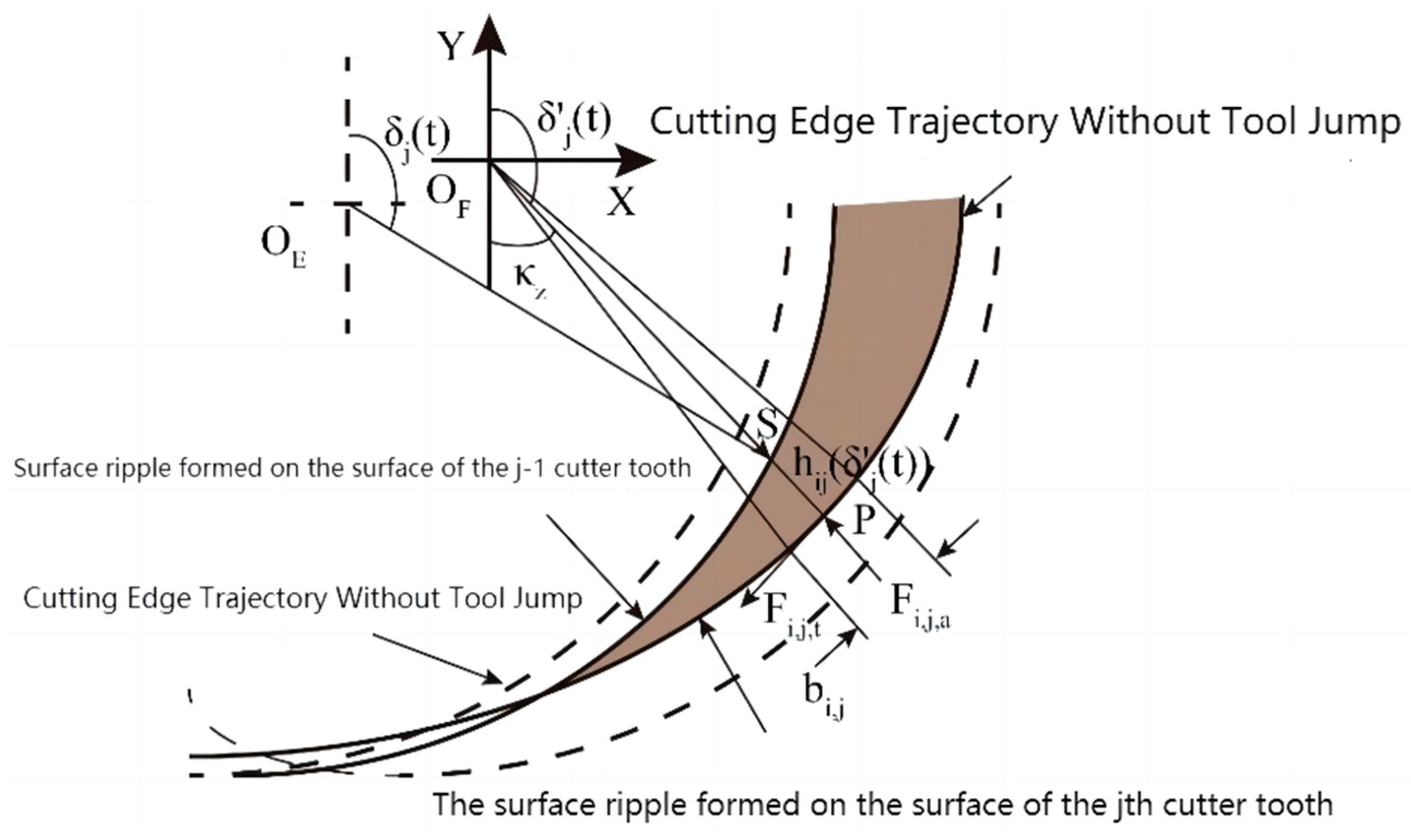
The cutting thickness in the machining process is a function of the contact angle between the current local arbitrary tooth point and the tool, which is specifically expressed as the distance between the subcycloid motion trajectory of the current tooth and the previous tooth. Figure 6 defines the subcycloid trajectory of the (j − 1) th tooth and the jth tooth of the two-edge flat-end milling cutter.
Due to the existence of the tool runout, the offset of the cycloid motion trajectory of the tooth is as follows [33,34]:
x e = ( R i , j z R z ) sin γ ψ + 2 π j N
y e = ( R i , j z R z ) cos γ ψ + 2 π j N
Based on the offset of the cycloidal motion trajectory of the tooth, the coordinates of the S point on the (j − 1) th tooth are known as follows:
x S = f z t + ( R i , j z R z ) sin γ 0 + ω t ψ + j 1 2 π N + R s i n δ j ( t )
y S = ( R i , j z R z ) cos γ 0 + ω t ψ + j 1 2 π N + R c o s δ j ( t )
Accordingly, the coordinate of point P on the jth tooth can be expressed as
x P = f z t + ( R i , j z R z ) sin γ 0 + ω t ψ + 2 π j N + R s i n δ j ( t )
y P = ( R i , j z R z ) cos γ 0 + ω t ψ + 2 π j N + R c o s δ j ( t )
In order to solve the time value t, an iterative method based on the Newton–Raphson method is used. It can be seen from the point S, P, O in a straight line.
t a n δ j ( t ) = x P x S y P y S
The undeformed cutting thickness calculated by the distance formula between the two points is the following:
h i , j δ = x P x S 2 + y P y S 2
= t a n 2 δ j ( t ) + 1 ( R i , j z R z ) cos γ 0 + ω t ψ + 2 π j N + R c o s δ j ( t ) ( R i , j z R z ) cos γ 0 + ω t ψ + j 1 2 π N + R c o s δ j ( t )
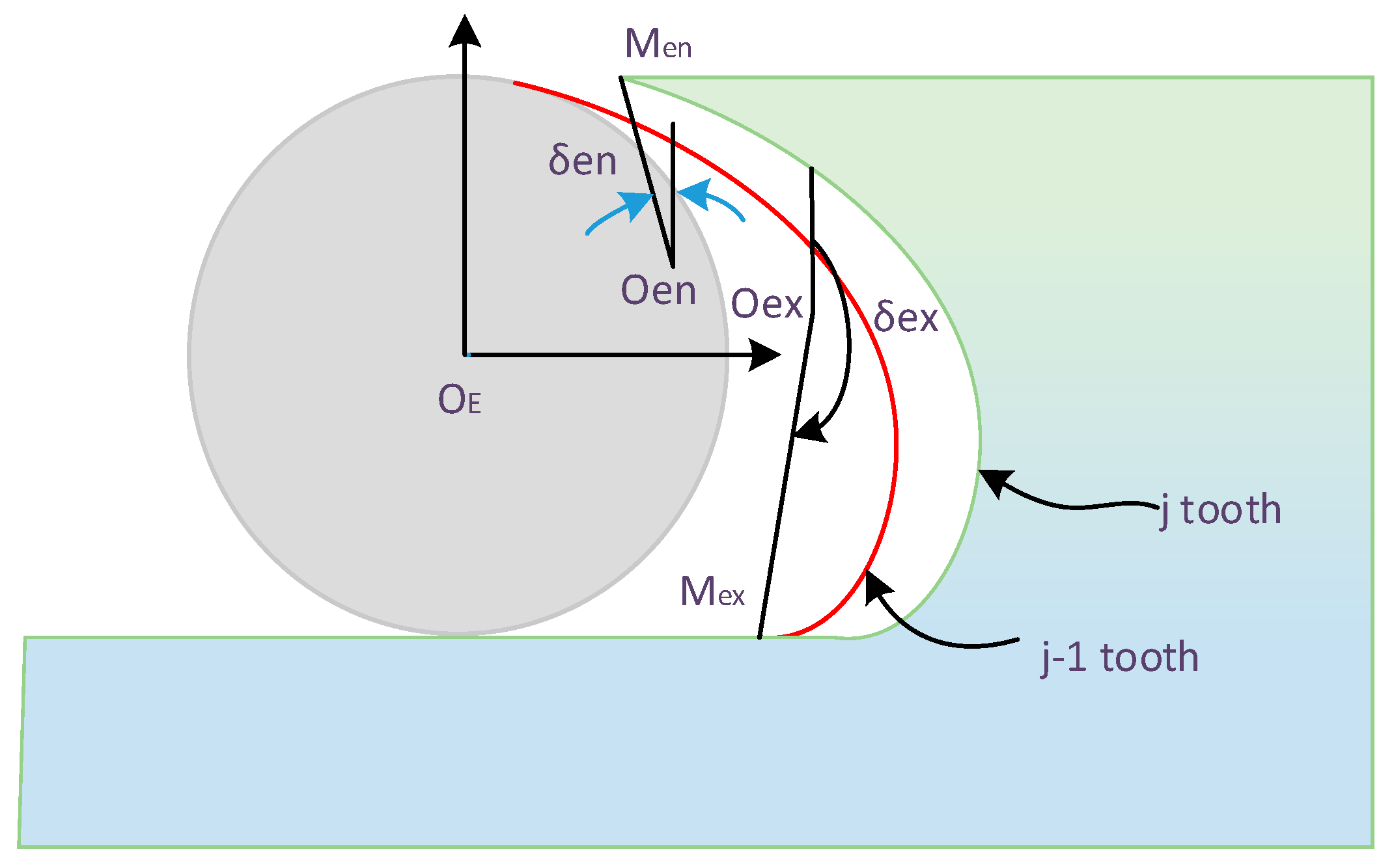
The Newton–Raphson iterative method in the literature is used to solve the undeformed cutting thickness model in the milling process of the flat-end milling cutter. On this basis, the cutting-in angle and cutting-out angle models of the cutter teeth are established as shown in Figure 7, and the cutting-in angle δ en and cutting-out angle δ e x of the cutter teeth under the undeformed cutting thickness model are calculated.
In order to calculate δ e n and δ e x , the coordinate values of M e n and M e x need to be calculated first. M e n is the point on the trochoid trajectory of the j − 1th tooth, and its coordinates can be written as follows:
x M e n = x O e n + R s i n δ t e n
y M e n = y O e n + R c o s δ t e n
where is the center position of the j − 1th tooth corresponding to M e n , and is the time point of the j − 1th tooth corresponding to t e n . Bringing the values of x O e n and y O e n on the j − 1 tooth into the above formula enables us to calculate the following:
x M e n = f z t e n + ( R i , j z R z ) sin γ 0 + ω t e n ψ + 2 π j N + R s i n δ j ( t e n )
y M e n = ( R i , j z R z ) cos γ 0 + ω t e n ψ + j 1 2 π N + R c o s δ j ( t e n )
Similarly, because the coordinates of point M e x are also on the subcycloid trajectory of the jth tooth, it can be written as the following:
x M e n = x O e n + R s i n δ t e n
y M e n = y O e n + R c o s δ t e n
Among them, O e n is the center position of the j tooth corresponding to M e n , and t e n is the time point of the j tooth corresponding to M e n . One must bring the values of x O e n and y O e n on the jth tooth into the above formula to obtain the following:
x M e n = f z t e n + ( R i , j z R z ) sin γ 0 + ω t e n ψ + 2 π j N + R s i n δ j ( t e n )
y M e n = ( R i , j z R z ) cos γ 0 + ω t e n ψ + j 1 2 π N + R c o s δ j ( t e n )
The equation can form a nonlinear equation set of variables containing t e n   and   t e n , and the following relation is obtained:
f t = f 1 t f 2 t = f 1 t e n , t e n f 2 t e n , t e n
among,   t = t e n , t e n T
f 1 t e n , t e n = f z t e n + ( R i , j z R z ) sin γ 0 + ω t e n ψ + 2 π j N + R s i n δ j ( t e n ) f z t e n ( R i , j z R z ) sin γ 0 + ω t e n ψ + 2 π j N R s i n δ j ( t e n ) = 0
f 2 t e n , t e n = ( R i , j z R z ) cos γ 0 + ω t e n ψ + j 1 2 π N + Rcos δ j ( t e n ) ( R i , j z R z ) cos γ 0 + ω t e n ψ + j 1 2 π N R c o s δ j ( t e n ) = 0
The Newton–Raphson iterative method is used to solve the nonlinear equations of point M e n , and t is obtained. The cut-in angle δ e n is as follows:
δ e n = a r c t a n x M e n x O e n y M e n y O e n
Use a similar method to find the cut-out angle δ e x . The coordinates of point M e x on the subcycloid trajectory of the j − 1 tooth are expressed as follows:
x M e x = f z t e x + ( R i , j z R z ) sin γ 0 + ω t e x ψ + 2 π j N + R s i n δ j ( t e x )
y M e x = ( R i , j z R z ) cos γ 0 + ω t e x ψ + j 1 2 π N + R c o s δ j ( t e x )
where t e x is the time point of M e x corresponding to the jth tooth. The cut-out angle δ e x is:
δ e x = a r c t a n x M e x x O e x y M e x y O e x

3. Establishment of Milling Force Models for Titanium Alloy Thin-Walled Parts

The milling force is discretized into K micro-cutting forces in the axial direction of the tool (z-axis direction). When the time parameter is t, the three-dimensional milling force components acting on the ith cutting element on the cutting-edge jth are the micro tangential cutting-force F i , j , t , micro radial cutting-force F i , j , r and micro axial cutting-force F i , j , a , as shown in Figure 8. a p is the axial cutting depth of the tool.
The three-dimensional milling force micro-element component can be expressed as follows [10]:
F i , j , t t = K t c h i , j ( δ j t ) z i , j + K t e z i , j
F i , j , r t = K r c h i , j ( δ j t ) z i , j + K r e z i , j
F i , j , a t = K a c h i , j ( δ j t ) z i , j + K a e z i , j
In the formula, K t e , K r e and K a e are the edge force coefficients; K t c , K r c and K a c are the cutting-force coefficients; z i , j is the axial height; and h i , j ( δ j t ) is the undeformed cutting thickness, which is solved by the formula. The three-dimensional milling force micro-element is mapped to the X, Y and Z directions by coordinate transformation to obtain the following:
F i , j , X t F i , j , Y t F i , j , Z t = T i , j , t t F i , j , t t F i , j , r t F i , j , a t
where
T i , j , t t = c o s δ j ( t ) s i n κ z s i n δ j ( t ) c o s κ z s i n δ j ( t ) s i n δ j ( t ) s i n κ z c o s δ j ( t ) c o s κ z c o s δ j ( t )                 0 c o s κ z s i n κ z
The total cutting force is obtained by adding up the forces on all the tooths:
F X δ j t F Y δ j t F Z δ j t = i , j F i , j , X t F i , j , Y t F i , j , Z t

4. Identification of Milling Force Coefficient

4.1. Experimental Theory of Milling Force Coefficient

In order to obtain the milling force coefficient for a new milling cutter, the use of a full-tooth (such as a milling groove) milling experiment is most convenient. In this case, the cut-in angle is 0 and the cut-out angle is π.
The average milling force can be expressed as the sum of linear functions of feed speed (C) and cutting-edge force:
F q ¯ = F ¯ q c f + F ¯ q e   q = x , y , z
Therefore, the component of the average force at each feed rate can be measured by the whole tooth-cutting experiment, and the corresponding milling force coefficient can be obtained according to the linear regression method.

4.2. Laboratory Equipment

The machine tool used in this experiment is Zhongjie TH5650 vertical machining center. The machining center adopts an operating system and has four machining axes: X axis, Y axis, Z axis and rotating B axis. Its positioning is accurate, and the processing is stable, which can ensure the accuracy of the experiment. The basic performance parameters of the machine are shown in Table 1.
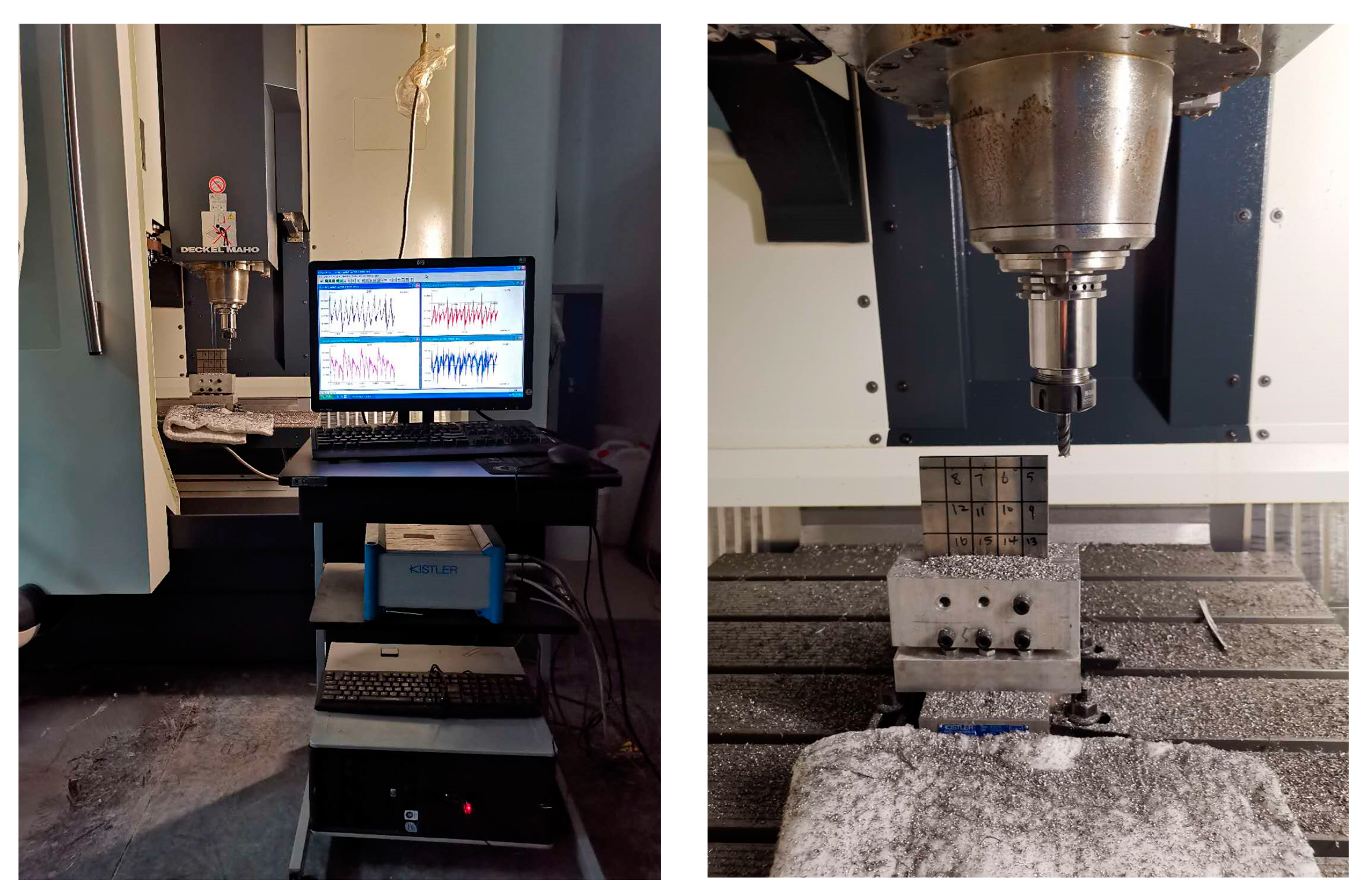
The tool used in the experiment is a two-edge flat-end milling cutter coated with Zhuzhou Diamond high-speed tungsten steel. The tool diameter is 10 mm and the spiral angle is 45°. The workpiece material used is TC4 titanium alloy, which is fixed on the dynamometer through the corresponding fixture. The experimental dynamometer model Kistler- 9257B and the dynamometer can simultaneously measure x, y and z in three directions of instantaneous cutting force and cutting torque size. It mainly includes a charge amplifier, a dynamometer and related lines. After connecting the dynamometer to the computer, the measured data can be stored and analyzed by the supporting analysis software, Dyno Ware. The dynamometer adopts the piezoelectric principle to measure dynamic cutting force and has high dynamic response characteristics. At the same time, it has an ultra-wide measuring range on the x, y and z axes and also has an ultra-high sampling frequency. The dynamometer is suitable for five-axis machining, large size, large quality, complex parts machining, and high dynamic precision cutting applications. The schematic diagram of the experimental equipment is shown in Figure 9:
The overhang is 50 mm, and the type of toolholder is SK40. The flank, rake angles and corner radius are 10°, 3° and 80°. The sampling frequency is 7000 Hz. Applied filtering is bandpass filtering which is limited to the range of 300 Hz and 3500 Hz. The cutting parameters used in the experiment are described in the succeeding pages of this paper, and the cutting parameters and the average milling force are listed in Table 2.
The data obtained from the experiment are brought into the formula, and the linear regression calculation is carried out. The milling force coefficient can be calculated as shown in Table 3.

5. Experimental Verification and Result Analysis

The traditional dial indicator is used to measure the tool runout parameters. In order to reduce the error, three measurements are carried out. The final measured tool runout parameter values are shown in Table 4.
The experimental processing platform is shown in Figure 10. The machine tool used for the experiment is DMG DMC635V vertical machining center, which adopts the Siemens operating system, and its accurate positioning and smooth machining can ensure the accuracy of the experiment. The tool used in the experiment is a 4-flute flat-head milling cutter with a tool diameter of 10 mm and a helix angle of 45°. The workpiece material used is TC4 titanium alloy, which is fixed to the force tester through the corresponding fixture. The force gauge is connected to a computer, and the measured data can be stored and analyzed with the analysis software DynoWare.
The processing parameters of the thin-walled parts are shown in Table 5. The size of the thin-walled parts is 100 mm × 100 mm × 5 mm. In the experiment, four bolts are used to fix the thin-walled parts.
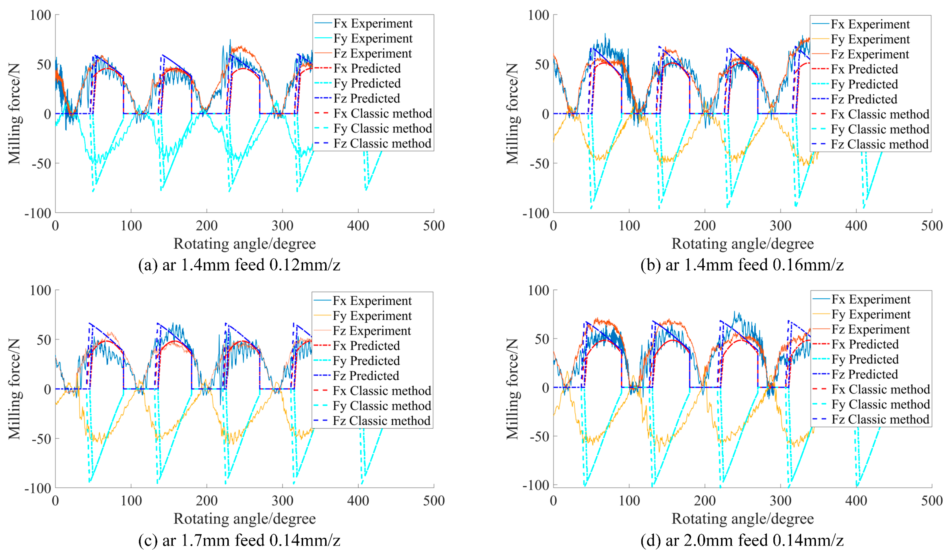
In order to further verify the accuracy of the cutting-force model proposed in this paper, experimental signals, classical methods and this model are compared under different processing parameters, as shown in Figure 11. It can be seen from Figure 10 that under different feed rates and different radial cutting depths, the predicted milling force is in good agreement with the milling force measured in the experiment. It can be seen that the simulated milling force is close to the experimental milling force, indicating that the proposed milling force model considering tool runout and workpiece deformation can accurately predict the milling force.
In order to illustrate its effectiveness, the relative error of the maximum value is used to judge. Table 6 lists the experimental milling forces under different feed rates, the milling forces predicted by the classical model, and the relative errors of the milling forces predicted by the model considering tool runout and workpiece deformation.
In the z direction, the proposed model and the traditional basic method show relatively small relative errors. However, the error of the proposed model is smaller than that of the traditional basic method. In the y direction, both the proposed model and the traditional basic method show relatively large relative errors.
However, the error of the proposed model is far less than that of the traditional basic method. The maximum error of the traditional basic method is 87.09%. However, the maximum error of the proposed model is only 66.54%.
In Table 7, in the x direction, the proposed model and the traditional basic method show the same small relative error. In the z direction, the proposed model and the traditional basic method show relatively small relative errors. However, the error of the proposed model is smaller than that of the traditional basic method. In the y direction, both the proposed model and the traditional basic method show relatively large relative errors. However, the error of the proposed model is far less than that of the traditional basic method. The maximum error of the traditional basic method can reach 89.45%. The maximum error of the proposed model is only 53.88%.

6. Conclusions

In this paper, the true motion track of cutting-edge hypocycloid motion is introduced into the undeformed cutting thickness model. Based on the linear cutting-force model, considering the influence of tool runout and workpiece deformation, a cutting-force model for thin-walled parts is established. Based on the cutting-force experiment, the cutting-force coefficient of titanium alloy was determined, and the tool runout parameters were obtained. Finally, the force obtained from the milling thin-walled parts experiment is compared with the classical prediction model and the prediction model proposed in this paper. The detailed conclusions can be drawn as follows:
(1) The error of the proposed model is far less than that of the traditional basic method. The maximum error of the traditional basic method is 87.09%. However, the maximum error of the proposed model is only 66.54%. It shows that the proposed model is more effective than the classical method.
(2) The relative error of the maximum value shows that the milling force prediction model established in this paper considering tool runout and workpiece deformation is basically the same as the experimental results and has a high degree of coincidence, which verifies the correctness of the simulation model cutting force. The results show that the model can be used to predict the cutting force of thin-walled parts. However, there are still some deficiencies in the establishment of the theoretical model, which needs further study.

Author Contributions

Conceptualization, M.X. (Miao Xie) and X.Y.; methodology, X.Y.; software, W.B.; validation, C.L., M.X. (Min Xia) and X.Y.; formal analysis, M.X. (Miao Xie); investigation, W.B.; resources, X.Y.; data curation, M.X. (Miao Xie); writing—original draft preparation, M.X. (Miao Xie); writing—review and editing, X.Y.; visualization, C.L.; supervision; project administration, X.Y.; funding acquisition, C.L. All authors have read and agreed to the published version of the manuscript.

Funding

This work was supported in part by the Startup Research Fund of Liaoning Petrochemical University 2021XJJL-005, in part by the Liaoning Province Doctoral Research Start-up Fund Project (2022-BS-293), in part by the Fushun Revitalization Talents Program FSYC202207005, and in part by the Basic Scientific Research Project of Liaoning Provincial Department of Education (General Project) LJKMZ20220718.

Data Availability Statement

The data that support the findings of this study are available from the corresponding author upon reasonable request.

Conflicts of Interest

The authors declared that they have no conflict of reproducing any published material (figures, schemes, tables, or any extract of a text) that does not fall into the public domain. We declare that we do not have any commercial or associative interest that represents a conflict of interest in connection with the work submitted.

Nomenclature

h uncut chip thickness
f z the feed per tooth
δ the tool contact angle
ρ eccentric distance
γ position angle of the eccentric
τ tangle
ϕ position angle of the tilt angle
L the hanging length of the tool after installation
Dthe radial of the cutter.
Hthe length of the cutting edge.
R actual cutting radius
ψ lag angle
β helix angle
φ rotation angle
ω the angular velocity of the spindle
t the cutting time
N the number of milling cutter teeth
a r the radial cutting depth
x e offset of tool cycloid motion path in x direction
y e offset of tool cycloid motion path in y direction
δ e n the cutting-in angle
δ e x cutting-out angle
M e n the point on the trochoid trajectory of the j − 1th tooth
O e n the center position of the j tooth corresponding to M e n
t e n the time point of the J tooth corresponding to M e n
M e x the subcycloid trajectory of the j − 1 tooth
t e x the time point of M e x corresponding to the jth tooth
K t e , K r e , K a e the edge force coefficients
K t c , K r c , K a c cutting-force coefficients
z i , j the axial height
h i , j δ j t the undeformed cutting thickness
a p the axial cutting depth of the tool

References

  1. Andersson, C.; Andersson, M.; Ståhl, J.E. Experimental studies of cutting force variation in face milling. Int. J. Mach. Tools Manuf. 2011, 51, 67–76. [Google Scholar] [CrossRef]
  2. Matsumura, T.; Tamura, S. Cutting Force Model in Milling with Cutter Runout. Procedia CIRP 2017, 58, 566–571. [Google Scholar] [CrossRef]
  3. Dargusch, M.S.; Sun, S.; Ji, W.K.; Li, T.; Trimby, P.; Cairney, J. Effect of tool wear evolution on chip formation during dry machining of Ti-6Al-4V alloy. Int. J. Mach. Tools Manuf. 2017, 126, 86–98. [Google Scholar] [CrossRef]
  4. Liu, C.; Wu, J.Q.; Li, G.H.; Tan, G.Y. Frequency-spectrum cha-racteristics of force in end milling with tool wear and eccentricity. Int. J. Adv. Manuf. Technol. 2013, 67, 925–938. [Google Scholar] [CrossRef]
  5. Armarego, E.J.A.; Deshpande, N.P. Computerized End-Milling Force Predictions with Cutting Models Allowing for Eccentricity and Cutter Deflections. CIRP Ann.-Manuf. Technol. 1991, 40, 25–29. [Google Scholar] [CrossRef]
  6. Liang, S.Y.; Wang, J. Milling force convolution modeling for identification of cutter axis offset. Int. J. Mach. Tools Manuf. 1994, 34, 1177–1190. [Google Scholar] [CrossRef]
  7. Shi, H.R. An analytical expression for end milling forces and tool deflection using Fourier series. Int. J. Adv. Manuf. Technol. 2012, 59, 37–46. [Google Scholar]
  8. Cao, Q.; Xue, D.; Zhao, J.; Li, Y. A cutting force model considering influence of radius of curvature for sculptured surface machining. Int. J. Adv. Manuf. Technol. 2011, 54, 821–835. [Google Scholar] [CrossRef]
  9. Cao, Q.; Zhao, J.; Han, S.; Chen, X. Force coefficients identification considering inclination angle for ball-end finish milling. Precis. Eng. 2012, 36, 252–260. [Google Scholar] [CrossRef]
  10. Wan, M.; Zhang, W.H.; Qin, G.H.; Tan, G. Efficient calibration of instantaneous cutting force coefficients and runout parameters for general end mills. Int. J. Mach. Tools Manuf. 2007, 47, 1767–1776. [Google Scholar] [CrossRef]
  11. Wan, M.; Zhang, W.-H.; Dang, J.-W.; Yang, Y. New procedures for calibration of instantaneous cutting force coefficients and cutter runout parameters in peripheral milling. Int. J. Mach. Tools Manuf. 2009, 49, 1144–1151. [Google Scholar] [CrossRef]
  12. Desai, K.A.; Agarwal, P.K.; Rao, P.V.M. Process geometry modeling with cutter runout for milling of curved surfaces. Int. J. Mach. Tools Manuf. 2009, 49, 1015–1028. [Google Scholar] [CrossRef]
  13. Zhu, Z.; Yan, R.; Peng, F.; Duan, X.; Zhou, L.; Song, K.; Guo, C. Parametric chip thickness model based cutting forces estimation considering cutter runout of five-axis general end milling. Int. J. Mach. Tools Manuf. 2016, 101, 35–51. [Google Scholar] [CrossRef]
  14. Wan, M.; Zhang, W.H. Calculations of chip thickness and cutting forces in flexible end milling. Int. J. Adv. Manuf. Technol. 2005, 29, 637–647. [Google Scholar] [CrossRef]
  15. Ratchev, S.; Govender, E.; Nikov, S.; Phuah, K.; Tsiklos, G. Force and deflection modelling in milling of low-rigidity complex parts. J. Mater. Process. Technol. 2003, 143–144, 796–801. [Google Scholar] [CrossRef]
  16. Ratchev, S.; Liu, S.; Huang, W.; Becker, A.A. An advanced FEA based force induced error compensation strategy in milling. Int. J. Mach. Tools Manuf. 2006, 46, 542–551. [Google Scholar] [CrossRef]
  17. Faassen, R.P.H.; Van De Wouw, N.; Nijmeijer, H.; Oosterling, J.A.J. An Improved Tool Path Model Including Periodic Delay for Chatter Prediction in Milling. J. Comput. Nonlinear Dyn. 2007, 2, 167. [Google Scholar] [CrossRef]
  18. Rodríguez, P.; Labarga, J.E. A new model for the prediction of cutting forces in micro-end-milling operations. J. Mater. Process. Tech. 2013, 213, 261–268. [Google Scholar] [CrossRef]
  19. Kaymakci, M.; Kilic, Z.M.; Altintas, Y. Unified cutting force model for turnin-g, boring, drilling and milling operations. Int. J. Mach. Tools Manuf. 2012, 55, 34–45. [Google Scholar] [CrossRef]
  20. Safari, H.; Sharif, S.; Izman, S.; Jafari, H.; Kurniawan, D. Cutting Force and Surface Roughness Characterization in Cryogenic High-Speed End Milling of Ti6Al-4V. Adv. Manuf. Process. 2014, 29, 350–356. [Google Scholar] [CrossRef]
  21. Azeem, A.; Feng, H.Y. Cutting force prediction for ball-end mills with non-horizontal and; rotational cutting motions. Int. J. Adv. Manuf. Technol. 2013, 67, 1833–1845. [Google Scholar] [CrossRef]
  22. Ji, C.; Li, Y.; Qin, X.; Zhao, Q.; Sun, D.; Jin, Y. 3D FEM simulation of helical milling hole process for titanium alloy Ti-6Al-4V. Int. J. Adv. Manuf. Technol. 2015, 81, 1733–1742. [Google Scholar] [CrossRef] [Green Version]
  23. Altintaş, Y.; Lee, P. A General Mechanics and Dynamics Model for Helical End Mills. Ann. Cirp 1996, 45, 59–64. [Google Scholar] [CrossRef]
  24. Izamshah, R.; Yuhazri, M.Y.; Hadzley, M.; Ali, M.A.; Subramonian, S. Effects of End Mill Helix Angle on Accuracy for Machining Thin-Rib Aerospace Component. Appl. Mech. Mater. 2013, 315, 773–777. [Google Scholar] [CrossRef]
  25. Mohd Hadzley, A.B.; Nurul Fatin, M.R.; Izamshah, R.; Siti Sarah, A.; Kasim, M.S.; Ali, M.A.; Sulaiman, M.A. Effects of Helix Angle on Cutting Performance for Machining Thin-Wall Aerospace Monolithic Component. Appl. Mech. Mater. 2014, 699, 3–8. [Google Scholar] [CrossRef]
  26. Arnaud, L.; Gonzalo, O.; Seguy, S.; Jauregi, H.; Peigné, G. Simulation of low rigidity part machining applied to thin-walled structures. Int. J. Adv. Manuf. Technol. 2011, 54, 479–488. [Google Scholar] [CrossRef]
  27. Altintas, Y. Discrete-Time Prediction of Chatter Stability, Cutting Forces, and Surface Location Errors in Flexible Milling Systems. J. Manuf. Sci. Eng. 2012, 134, 61–69. [Google Scholar]
  28. Kuntoğlu, M.; Aslan, A.; Pimenov, D.Y.; Usca, Ü.A.; Salur, E.; Gupta, M.K.; Mikolajczyk, T.; Giasin, K.; Kapłonek, W.; Sharma, S. A Review of Indirect Tool Condition Monitoring Systems and Decision-Making Methods in Turning: Critical Analysis and Trends. Sensors 2021, 21, 108. [Google Scholar] [CrossRef]
  29. Salur, E.; Aslan, A.; Kuntoglu, M.; Gunes, A.; Sahin, O.S. Experimental study and analysis of machinability characteristics of metal matrix composites during drilling. Compos. Part B Eng. 2019, 166, 401–413. [Google Scholar] [CrossRef]
  30. Wojciechowski, S.; Matuszak, M.; Powałka, B.; Madajewski, M.; Maruda, R.W.; Królczyk, G.M. Prediction of cutting forces during micro end milling considering chip thickness accumulation. Int. J. Mach. Tools Manuf. 2019, 147, 103466. [Google Scholar] [CrossRef]
  31. Wojciechowski, S.; Mrozek, K. Mechanical and technological aspects of micro ball end milling with various tool inclinations. Int. J. Mech. Sci. 2017, 134, 424–435. [Google Scholar] [CrossRef]
  32. Wojciechowski, S. The estimation of cutting forces and specific force coefficients during finishing ball end milling of inclined surfaces. Int. J. Mach. Tools Manuf. 2015, 89, 110–123. [Google Scholar] [CrossRef]
  33. Li, X.P.; Li, H.Z. Theoretical modelling of cutting forces in helical end milling with cutter runout. Int. J. Mech. Sci. 2004, 46, 1399–1414. [Google Scholar] [CrossRef]
  34. Li, H.Z.; Liu, K.; Li, X.P. A new method for determining the undeformed chip thickness in milling. J. Mater. Process. Technol. 2001, 113, 378–384. [Google Scholar] [CrossRef]
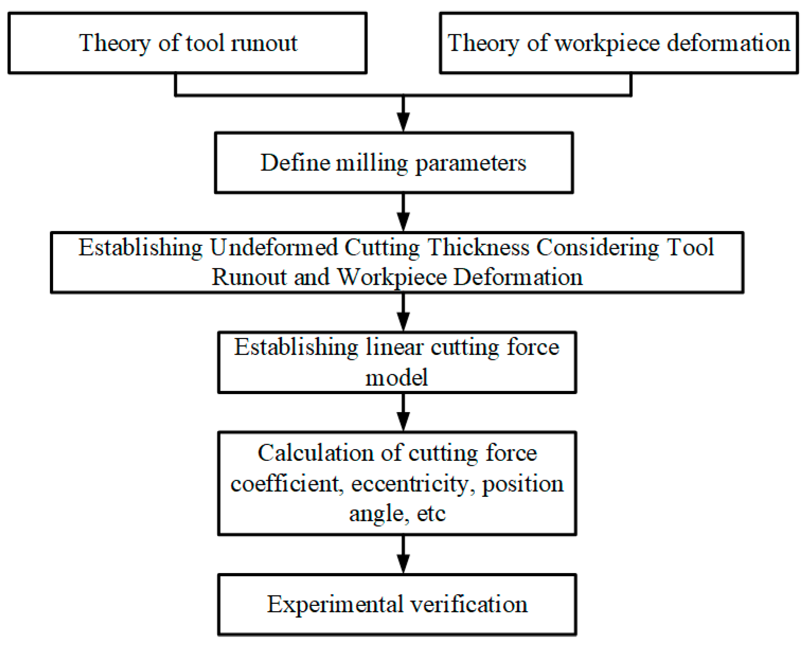
Figure 1. Flowchart of full-text method.
Electronics 12 00968 g001
Figure 2. Tool runout: (a) radial offset; (b) axis tilt.
Electronics 12 00968 g002
Figure 3. Milling model of thin-walled workpiece considering tool runout.
Electronics 12 00968 g003
Figure 4. Flat-end milling cutter geometry.
Electronics 12 00968 g004
Figure 5. Milling model of thin-walled workpiece considering deformation.
Electronics 12 00968 g005
Figure 6. Trochoid trajectory of the (j − 1)th and jth tooth in the end milling process.
Electronics 12 00968 g006
Figure 7. Entry and exit angle in the trochoid trajectory of tool edge.
Electronics 12 00968 g007
Figure 8. Infinitesimal milling modeling of end mill.
Electronics 12 00968 g008
Figure 9. Experimental-related equipment.
Electronics 12 00968 g009
Figure 10. Experimental setup.
Electronics 12 00968 g010
Figure 11. Comparison between experiment and simulation under different processing parameters.
Electronics 12 00968 g011
Table 1. TH5650 Vertical machining center parameters.
Main PerformanceParameter
Maximum spindle speed6000 r/min
Stroke (x, y, z)850 mm, 500 mm, 630 mm
Maximum spindle torque70/909 (continuous/30 min) N.M
Max fastest feed rateX, Y 24 m/min, Z 15 m/min
Maximum load of workbench500 kg
Power11/7.5 KW
Table 2. The milling force coefficient experiment data tables.
NumberSpindle Speed
(r/min)
Axial Cutting Depth (mm)Radial Cutting Depth (mm)Feed per Tooth
(mm/z)
X-Axis Average Force (N)Y-Axis Average Force (N)
110000.4100.0218.823.0
210000.4100.0320.525.7
310000.4100.0423.533.0
410000.4100.0526.041.9
Table 3. The milling force coefficient tables.
Shear Force CoefficientNumerical Value (MPa)Tooth Force CoefficientNumerical Value (N/m)
K t c 1624.6 K t e 6.9
K r c 613.7 K r e 32.3
Table 4. Cutter’s parameters and measured results of the tool runout.
Cutting ToolDiameter (mm)Number of TeethHelix Angle (°)Eccentricity (mm)Position Angle of Eccentricity γ (°)
Flat-head-milling-machine102300.00275.33
Table 5. The processing parameters of thin-walled parts.
Spindle Speed
(r/min)
Axial Cutting Depth (mm)Radial Cutting Depth (mm)Feed per Tooth
(mm/z)
10000.50.50.01
Table 6. Relative error of different feed rates.
Feed Rate (mm/min)Fx (Proposed)Fx (Classical)Fy (Proposed)Fy (Classical)Fz (Proposed)Fz (Classical)
19817.80%16.50%43.21%63.85%13.46%18.92%
23427.40%22.38%47.83%75.21%5.68%8.84%
28823.24%24.56%66.54%87.09%4.62%3.76%
Table 7. Relative error of different feed rates.
Radial Depth (mm)Fx (Proposed)Fx (Classical)Fy (Proposed)Fy (Classical)Fz (Proposed)Fz (Classical)
0.315.06%19.08%56.01%89.45%25.16%32.48%
0.513.27%16.47%53.88%86.54%26.86%25.22%
0.722.04%24.51%56.43%65.34%6.55%7.58%
Disclaimer/Publisher’s Note: The statements, opinions and data contained in all publications are solely those of the individual author(s) and contributor(s) and not of MDPI and/or the editor(s). MDPI and/or the editor(s) disclaim responsibility for any injury to people or property resulting from any ideas, methods, instructions or products referred to in the content.