Article

Open-Circuit Fault-Tolerant Control of a Six-Phase Asymmetric Permanent Magnet Synchronous Motor Drive System

1
School of Electronic and Electrical Engineering, Zhengzhou University of Science and Technology, Zhengzhou 450064, China
2
School of Information Engineering, Henan University of Technology, Zhengzhou 450001, China
*
Author to whom correspondence should be addressed.
Electronics 2023, 12(5), 1131; https://doi.org/10.3390/electronics12051131
Submission received: 25 January 2023 / Revised: 18 February 2023 / Accepted: 22 February 2023 / Published: 25 February 2023
(This article belongs to the Section Systems & Control Engineering)

Abstract

:
One innovative composite fault-tolerant control tactic is presented for the reliable operation of a power transmission system, which consists of both an asymmetric six-phase permanent magnet synchronous motor (PMSM) and a T-type mid-point clamp type (T-NPC) three-level inverter. First, in order to inherit the better harmonic property of simplified space vector modulation (SVM) and the rapid dynamic capability of direct torque control (DTC), the SVM-DTC control scheme was determined, and the harmonic electric current suppression unit was added to the basic control scheme to obtain good harmonic electric current suppression. In addition, a strategy for open-circuit fault-tolerant control under the SVM-DTC scheme was designed by analyzing the mutual influence between the stator flux linkage and the stator voltage of each phase under an open-circuit fault. Finally, the PMSM drive system principle prototype was tested. By comparing the waveforms of output torque and current of each phase before and after fault tolerance, it shows that the large torque fluctuation (±5%) before fault tolerance was suppressed to ±2% and smoothed out, verifying the effectiveness of fault tolerance control.

1. Introduction

Due to the development of rare earth permanent magnet material technology, a large number of permanent magnet synchronous motors (PMSMs) have gradually received extensive attention and research from academia and industry. Due to its above-average power factor, high efficiency, and simple structure, it has been gradually applied in some fields with relatively high requirements for reliability, power level, and power density, especially in aerospace, naval propulsion, rail transportation, electric vehicles, etc. [1,2,3].
Multi-phase PMSM usually use T-type neutral point clamping (T-NPC) three-level inverters, which have the advantage of suppressing normal mode voltage, reducing voltage harmonics, improving efficiency, resisting electromagnetic interference, and fault-tolerant capability [4,5]. Faulty bridge arms are the most typical fault. Two-level inverters and diode-clamped inverters need to discard the faulty bridge arm completely, which will lead to incorrect magnetic chain calculations and make it difficult to balance the electric drive system. In the case of an open-circuit fault in the T-NPC inverter, the faulty phase can be connected to the DC neutral of the three-level inverter by circuit reconstruction, which, in combination with the neutral voltage control, allows fault-tolerant operation [6,7,8].
The literature [9] has described magnetic field orientation control tactics on the strength of improved space vector modulation (SVM), which can eliminate low harmonics, but with poor dynamic performance. The direct torque control (DTC) based on switching tables covered in the literature [10,11] has a fast dynamic response, but also larger harmonics. Study [12] combines the two control strategies to form an SVM-DTC scheme, which has the advantages of both, but is limited to three-phase motor applications. Study [13] investigates fault-tolerant control strategies for five-phase induction motors, but is limited to fault tolerance under the control of magnetic field directional control.
In order to build a low-voltage high-power electric drive system with highly reliable operation, this article has been redesigned and extended based on previous research, and a fault-tolerant control scheme for an asymmetric six-phase PMSM drive system is presented, together with an asymmetric winding form to eliminate the sixth harmonic [14,15,16]. The paper discusses the following:
(1) Based on the analysis of the characteristics between the winding voltage and magnetic circuit of six-phase PMSM, a spatial decoupling mathematical model was established;
(2) Added with an electric current harmonic suppression unit, the control tactics based on SVM-DTC was designed, which inherits the better harmonic property of SVM and the fast dynamic property of DTC. After implementation, the motor electric current harmonics were reduced and the flux linkage trajectory was stabilized;
(3) A semi-physical simulation platform PMSM was designed to validate the simulation of the winding phase failure. By comparing the waveforms of output torque and current of each phase before and after fault tolerance, it can be seen that the large torque fluctuation (±5%)before fault tolerance was suppressed to ±2% and smoothed out. The effectiveness of fault tolerance control was verified.

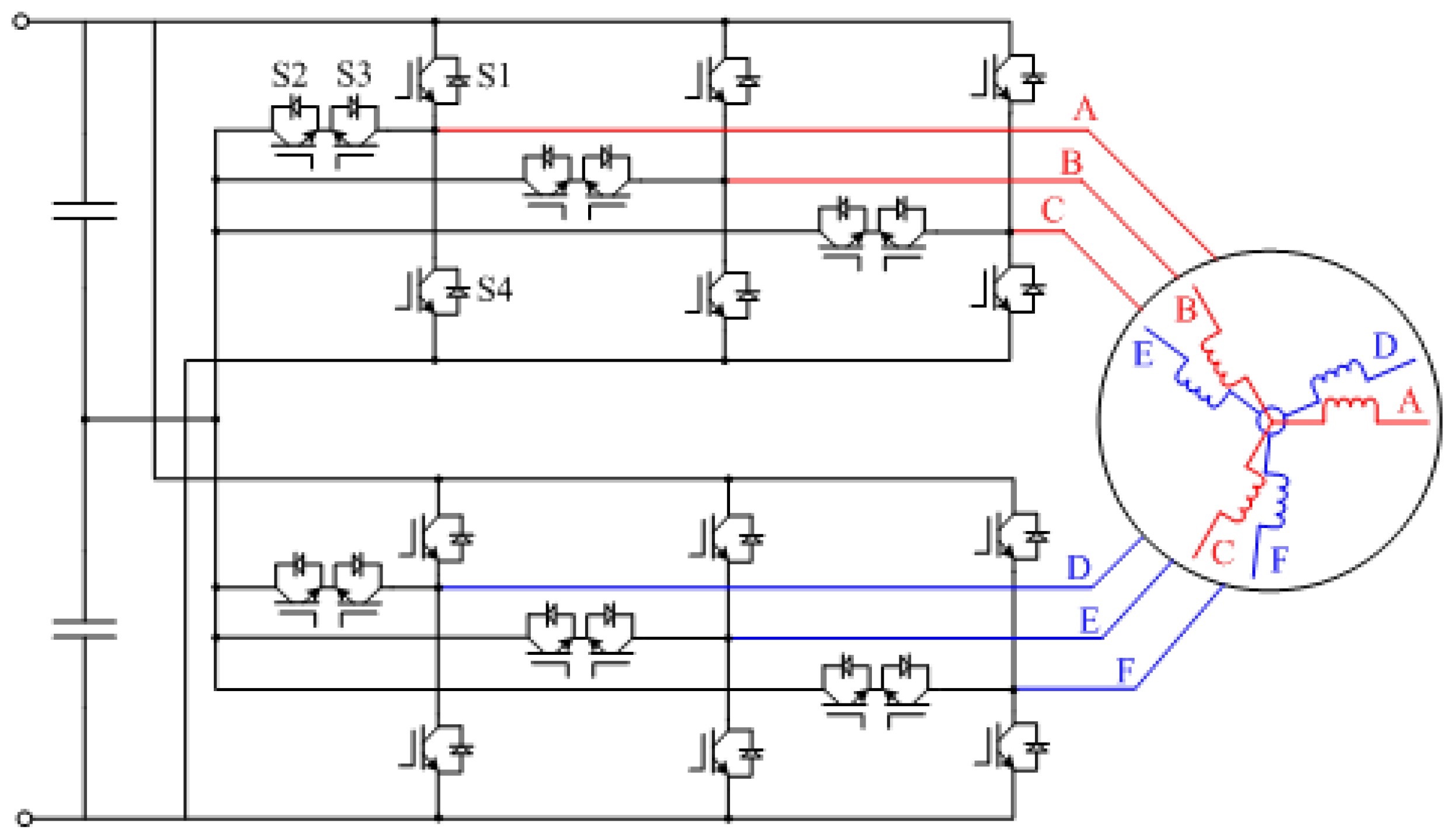
2. Six-Phase PMSM Drive System Configuration and Model

The configuration of the asymmetric six-phase PMSM drive system using a T-NPC inverter is shown in Figure 1, where the angle between each winding of the six-phase PMSM is 30°.
The equations for the voltage and flux linkage of the motor are [17]:
u s = R s i s + P Ψ s Ψ s = L s i s + Ψ f F ( θ )
where  u s  is the stator voltage,  i s  the stator electric current,  Ψ s  is the stator magnetic chain vector,  θ  is the phase angle between the A-phase winding and the d-axis,  Ψ f  is the rotor magnetic chain vector, P is the differential operator, and the function F( θ ) is specified in Equation (2):
F ( θ ) = [ c o s ( θ ) , c o s ( θ 2 Π 3 ) , c o s ( θ + 2 Π 3 ) , c o s ( θ Π 6 ) , c o s ( θ 5 Π 6 ) , c o s ( θ + Π 2 ) ] T
The inductance matrix  L s  can be expressed as:
L s = L l s I 6 + L m s A + L m r B
where  L l s  is the leakage inductance,  I 6  is the six dimensional identity matrix,  L m s  is the stator inductor, and  L m r  is the excitation inductor. Matrix A is shown in Equation (4); matrix B is shown in Equation (5) [18,19,20]:
A = 1 1 2 1 2 3 2 3 2 0 1 2 1 1 2 0 3 2 3 2 1 2 1 2 1 3 2 0 3 2 3 2 0 3 2 1 1 2 1 2 3 2 3 2 0 1 2 1 1 2 0 3 2 3 2 1 2 1 2 1
B = B 1 B 3 B 5 B 2 B 4 B 6 B 3 B 5 B 1 B 4 B 6 B 2 B 5 B 1 B 3 B 6 B 2 B 4 B 2 B 4 B 6 B 5 B 1 B 3 B 4 B 6 B 2 B 1 B 3 B 5 B 6 B 2 B 4 B 3 B 5 B 1
B 1 = c o s ( 2 θ ) B 2 = c o s ( 2 θ π 6 ) B 3 = c o s ( 2 θ 2 π 3 ) B 4 = c o s ( 2 θ 5 π 6 ) B 5 = c o s ( 2 θ 4 π 3 ) B 6 = c o s ( 2 θ 2 π 3 )
Based on the vector space decomposition method in the literature [21], the voltage and electric current vectors of the asymmetric six-phase PMSM can be decomposed into three two-dimensional orthogonal subspaces:  α - β , x-y, and  o 1 - o 2 . The following equation gives the decomposition matrix  T V S D .
T V S D = α β x y o 1 o 2 = 1 3 1 1 2 1 2 3 2 3 2 0 0 3 2 3 2 1 2 1 2 1 1 1 2 1 2 3 2 3 2 0 0 3 2 3 2 1 2 1 2 1 1 1 1 0 0 0 0 0 0 1 1 1

3. The SVM-DTC Control Method

The SVM-DTC control scheme for an asymmetric six-phase PMSM drive system is shown in Figure 2. The controller mainly consists of a speed closed loop, torque and flux linkage estimation, voltage vector prediction, simplified SVM, and harmonic electric current control modules.

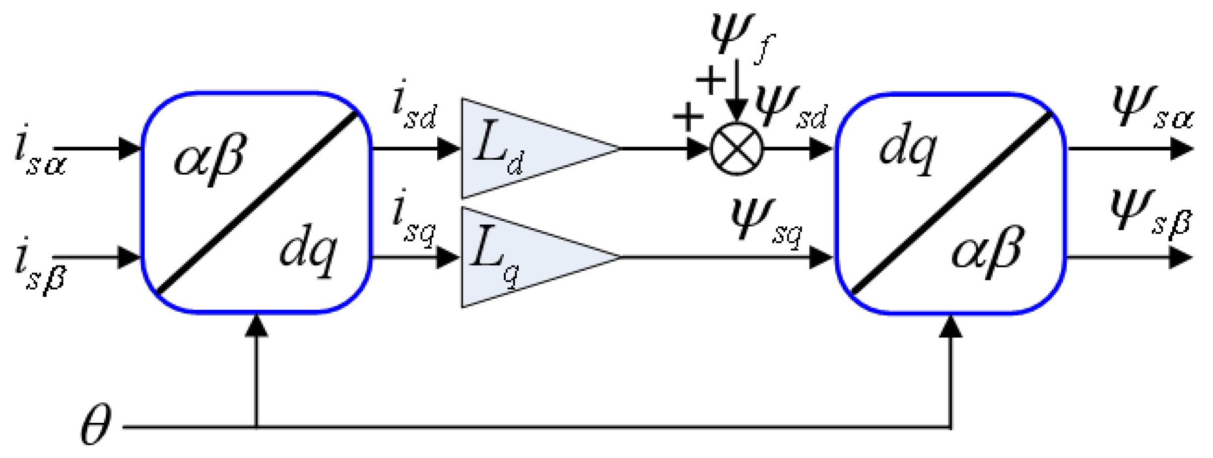
3.1. Torque and Magnetic Chain Estimation

The voltage model-based stator chain estimation increases the measurement error at startup and low speed due to the larger share of stator resistance voltage drop at low speed. The current model-based chain estimation is independent of the motor speed and is not constrained by the voltage signal, so that the stator chain can still be calculated accurately when an open-circuit fault occurs [22]. The motor torque calculation equation is shown in Equation (7), and the flow of the stator magnetic chain calculation on the ground of the current model is shown in Figure 3:
T e = 3 n p ( Ψ s α i s β Ψ s β i s α )
where  T e  is the electromagnetic torque,  n p  is the number of magnetic pole pairs,  Ψ s α  and  Ψ s β  are the  α β -axis stator flux linkage vectors, and  i s α  and  i s β  are the  α β -axis stator currents.

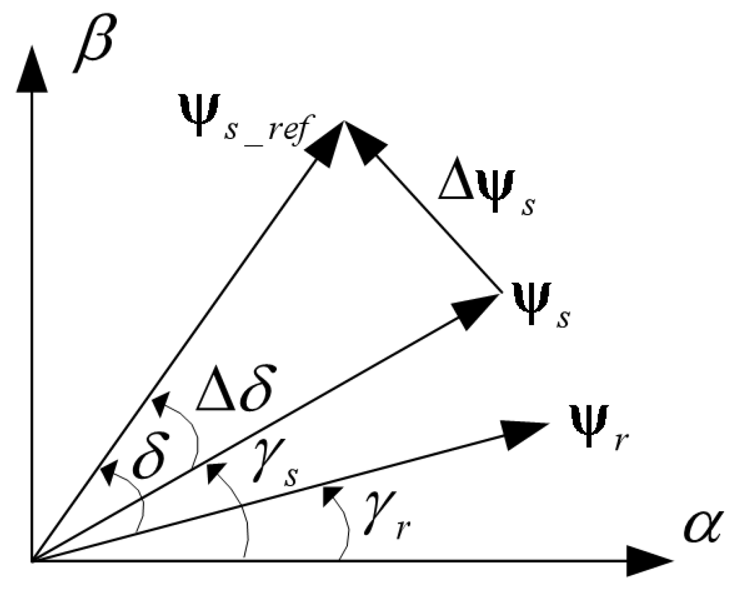
3.2. Voltage Vector Prediction
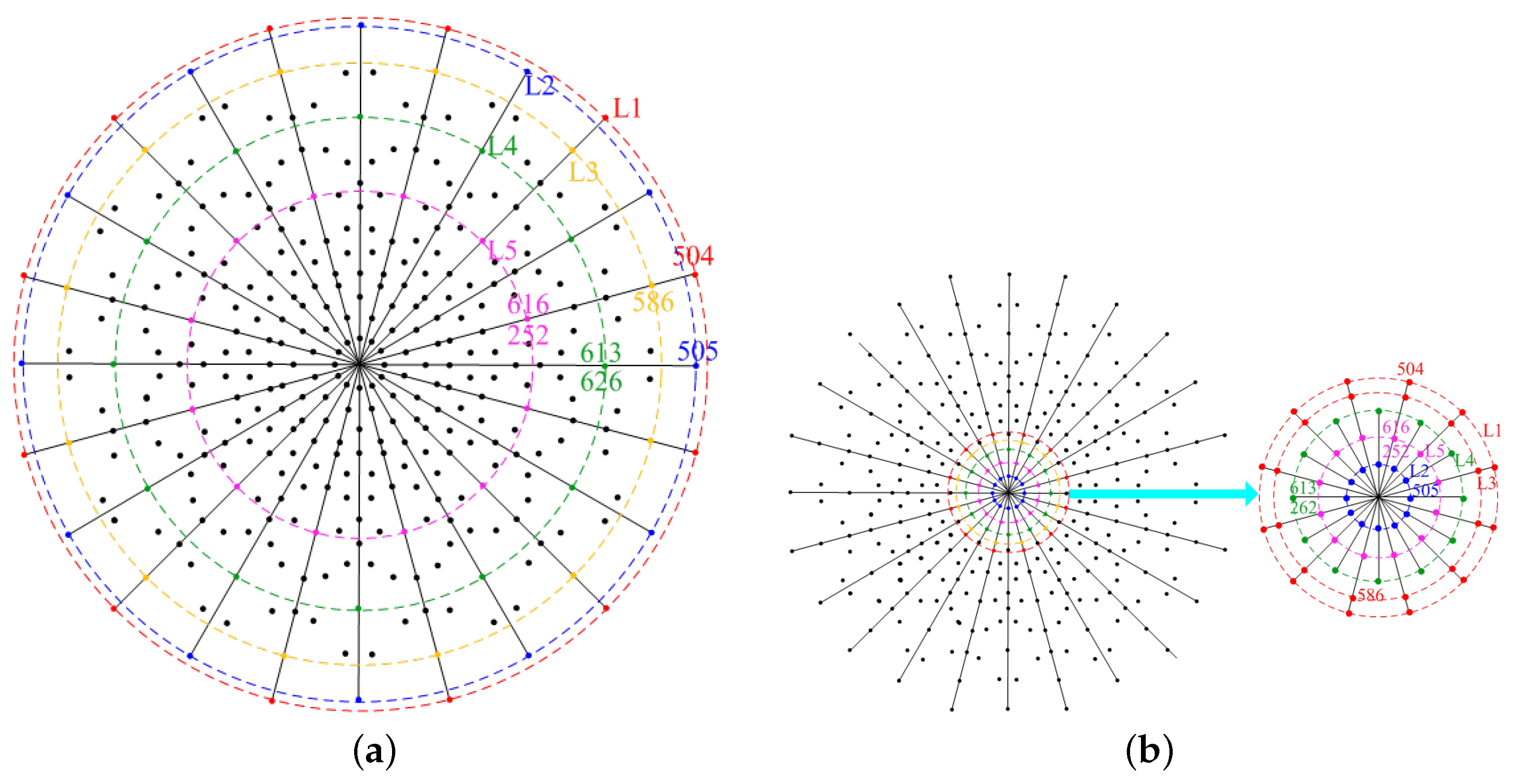
The stator flux linkage control schematic is shown in Figure 4, where  γ s  is flux linkage angle of the stator, and  γ r  is flux linkage angle of the rotor. The stator flux linkage vector inaccuracy  Δ Ψ s  determines the mutual influence between the stator flux linkage vector reference  Ψ s _ r e f  and the voltage vector reference  V r e f :
Δ Ψ s = Δ Ψ s _ r e f Ψ s = V r e f T s
where  T s  is the switching period.

3.3. Simplified SVM

The T-NPC inverter can output three levels per bridge arm,  U d c 2 , 0, and  U d c 2 , which can be represented by 2, 1, and 0 respectively. Each level in each phase corresponds to one switching state of an inverter, so that the six-phase outputs will be combined into 729 (36) voltage space vectors. The literature [23] demonstrated that the fifth and seventh harmonic currents inherent in the PMSM originate from non-zero vectors on the x-y subspace. One effective way to decrease harmonic currents is to keep the synthesis vector in the x-y subspace zero for each switching cycle by means of vector synthesis. However, the large number of raw voltage vectors makes it difficult to design a scheme for the space vector modulation method, so it needs to be simplified.
In order to optimize the voltage vector synthesis process, a simplified SVM scheme proposes a two-step vector sum synthesis method. In the first step, the volt-sec mean of the voltage vectors on the x-y subspace is equal to zero as a constraint, and the two initial vectors are synthesized into a new harmonic-free vector. The second step is to use the two synthetic harmonic-free vectors to synthesize the reference voltage vector [24,25]. The decomposition of the voltage vector synthesis process into two separate steps can largely reduce the complexity of the SVM scheme and facilitate the simplification of the initial vector. The simplification principle for the initial voltage vector is: (1) no level jumps between 2 and 0 during a single switching cycle; (2) maintaining a sufficient number of small voltage vectors to ensure balanced control of the voltage at the midpoint of the DC bus; (3) selection of as many peripheral vectors as possible on the  α - β  subspace to improve DC bus voltage utilization; (4) force the voltage vector mapping on the x-y subspace to zero.
The simplified vectors obtained based on the above principles are shown in Figure 5a,b, with the colored dots indicating the selected points. The 729 fundamental voltage vectors are mapped to the  α - β  and x-y subspace and described in decimal form. For instance, vector 210,201 can be expressed as decimal 586. According to the different magnitudes, the mapping of the simplified residual vectors on the  α - β  subspace can be totally divided into five groups:  L 1 L 2 L 3 L 4 , and  L 5 , and the magnitudes of the five groups of vectors are shown in Table 1.
The first step in the two-step voltage vector synthesis method is to form three new sets of anharmonic vectors,  L 1 3 L 3 5 , and  L 2 4 , from vectors of the same orientation in  L 1  and  L 3 L 3  and  L 5 , and  L 2  and  L 4 , respectively, on the  α - β  subspace.This results in the set of harmonic-free vectors on the x-y subspace shown in Figure 6. The constraint for the first step of vector synthesis is that the average volt-second of the voltage vector on the x-y subspace remains zero, so the duration can be calculated as shown in Table 2 P i j ( i )  and  P i j ( j )  are the time weight coefficients of  L i  and  L j , which sum to zero, and  L i  and  L j  are synthesized into  L i j . The amplitudes of  L 1 3 L 3 5 , and  L 2 4  can be calculated from Table 1, as shown in Table 3.
In the second step of the two-step voltage vector synthesis, the 36 newly synthesized harmonic-free vectors from the first step are divided into the 12 sectors I–XII shown in Figure 6. Each sector includes a zero vector V1 and five non-zero vectors V2–V6, which specifically dividing the sector into four areas A, B, C, and D. The reference voltage vector is synthesized from the three nearest adjacent vectors. For example, when the reference voltage vector is located in B, then V2, V3, and V5 are involved. If the midpoint DC voltage is lower than  U d c 2 , the voltage vectors used are 523 (201,201), 617 (211,212), 616 (211,211), 613 (211,201), 586 (210,201), and 505 (200,201).
The two-step vector synthesis method gives the vector duration distribution for the synthesis of the harmonic-free vector and the harmonic-free voltage vector duration distribution for the synthesis of the reference voltage vector, which in turn gives the initial vector duration distribution for the synthesis of the reference voltage vector. The duration of each vector is then converted into the action time of each level, and the action time of each level of each phase is superimposed on the adjustment time of each phase output by the harmonic current closed-loop controller to generate the pulse width modulation signal. The switching sequence of the I-sector B area vector corresponding to each phase is shown in Figure 7.

3.4. Current Harmonic Suppression

Although the aforementioned SVM tactics may astrict harmonics, there are still electric current harmonics caused by counter-electromotive force and asymmetric windings. Therefore, to compensate for the harmonic components, a harmonic subspace closed-loop controller is presented in this article, as shown in the red dashed box in Figure 2. The voltage references  u x r e f  and  u y r e f  are generated on the x-y subspace, and the six-phase voltage compensation values,  u A ~ u F , are generated by the inverse transformation of the decomposition matrix  T V S D . These compensating voltages are linearly converted into compensation for each phase of switching action, resulting in a final sequence of switching pulses.

3.5. Neutral Voltage Balance Control Strategy

Each switching tube is subjected to half of the DC voltage when the neutral point voltage of the three-level inverter is balanced. In contrast, the switching tubes are subjected to unequal voltages when the phase is missed. When an open-circuit fault occurs in one phase, whether the neutral point is isolated or not and how the neutral point is connected also correspond to different reduced-dimensional decoupling transformation matrices. This paper discusses an asymmetrical six-phase PMSM with two windings of a six-phase motor with isolated neutral operating independently. The two windings differs from each other by 30 degrees. In this case, both windings have their own constraints after a phase loss fault, i.e., the total current of phase A, B, C is zero and the total current of phase D, E, F is zero.

4. Open Circuit Fault Tolerance Strategy

In order to materialize fault-tolerant control of the system for open-circuit faults, it is first necessary to derive the voltage difference between the terminal voltage under normal conditions and the opposite electric potential of the fault in the event of an open-circuit fault.This voltage difference will be compensated for by the other non-faulted phases. As shown in Figure 8, let phase A be in open circuit fault, then the terminal voltage of phase A under normal condition is  u A , and the counter-electromotive force of the fault winding is  u E M A . The voltage difference between the two is  Δ u A .
Because the phase voltage of the asymmetric six-phase PMSM meets the symmetry constraint, the motor phase voltage can be calculated by the line voltage as Formula (10).
u A u B u C u D u E u F = 1 3 2 1 1 0 0 0 1 1 1 0 0 0 1 2 1 0 0 0 0 0 0 2 1 1 0 0 0 1 1 1 0 0 0 1 2 1 u A B u B C 0 u D E u E F 0
where  u A  to  u F  are the port voltages from phase A to phase F, and  u A B  to  u E F  are the line voltages from phase A to phase F. The voltages on the  α - β  and x-y subspaces can be obtained from Equations (7) and (10).
u α u β u x u y = 1 6 3 u A + 3 u D E 3 u B C + u D E + 2 u E F 3 u A 3 u D E 3 u B C + u D E + 2 u E F
When the A-phase open-circuit fault occurs, the line voltage,  u B C u D E , and  u E F  remain unchanged, whereas  u A  changes from the original original normal terminal voltage value to the total back electromotive force of A-phase. Both  u A  and  u x  will be affected. Therefore, the key is to find out the analytical expression of  Δ u A , and the expression of  u A  is shown in Equation (11):
u A = u B u C = R s ( i B + i C ) d d t ( Ψ B + Ψ C )
First,  d ( Ψ B + Ψ C ) / d t  of the above equation is calculated, and according to Equation (1), we can obtain:
Ψ B + Ψ C = L l s ( i B + i C ) + L m r ( i A + 1 2 i B + 1 2 i C 3 2 i D + 3 2 i E ) + [ c o s ( θ 2 Π 3 ) + c o s ( θ + 2 Π 3 ) ] Ψ f + ( Ψ m r B + Ψ m r C )
Ψ E Ψ D = L l s ( i E i D ) + 3 2 L m s ( i E i D + [ c o s ( θ 5 Π 6 ) c o s ( θ Π 6 ) ] Ψ f + ( Ψ m r E Ψ m r D ) )
where the excitation flux linkages  Ψ m r B Ψ m r C Ψ m r D , and  Ψ m r E  are the excitation flux linkages of phases B, C, D, and E. We have  Ψ m r = L m r [ B ] i s [ Ψ m r A , Ψ m r B , Ψ m r C , Ψ m r D , Ψ m r E , Ψ m r F ] T .
Considering  i A = 0 , i B + i C = 0 , a n d   i D + i E + i F = 0 , Equation (13) can be rewritten as:
Ψ B + Ψ c = 3 2 L m s ( i E i D ) + [ c o s ( θ 2 Π 3 ) + c o s ( θ + 2 Π 3 ) ] Ψ f + ( Ψ m r B + Ψ m r C )
Thereby, further derivation based on Equations (14) and (15) leads to:
3 2 L m s ( i E i D ) = ( Ψ E Ψ D ) L l s ( i E i D ) + [ c o s ( θ 5 Π 6 ) c o s ( θ Π 6 ) ] Ψ f + ( Ψ m r E Ψ m r D )
3 2 L m s ( i E i D ) = Ψ B + Ψ C [ c o s ( θ 2 Π 3 ) + c o s ( θ + 2 Π 3 ) ] Ψ f + ( Ψ m r B + Ψ m r C )
Combining Equations (16) and (17), we obtain:
Ψ B + Ψ C = 3 3 [ ( Ψ E Ψ D ) L l s ( i E i D ) ]
Substituting the above equation into Equation (12), the fault phase voltage is calculated as:
u A _ f a u l t = 3 3 [ u E D R s ( i E i D ) L l s d d t ( i E i D ) ]
According to Equation (11), in normal conditions, we can get  u A _ n o r m a l = 3 3 u D E  by controlling the X-axis voltage to zero, i.e.,   u x = 0 . Comparing with Equation (19), we can get the variation  u A  of  Δ u A  as:
Δ u A = 3 3 [ R s ( i E i D ) + L l s d d t ( i E i D ) ]
Based on (11) and (20), the stator voltage adjustment in  α - β  subspace after the fault is:
Δ u α = 3 6 [ R s ( i E i D ) + L l s d d t ( i E i D ) ] Δ u β = 0
In order to get a same voltage vector output when an open-circuit fault occurs, the reference voltage  u r e f _ β  does not need to be changed, whereas  u r e f _ α  should be added to  Δ u α . As the fault causes a change in the harmonic subspace, the control dimensions are reduced from six to five, so the harmonic vectors need to be derived by constructing a new five-dimensional orthogonal vector matrix. After removing phase A from Equation (6), Equation (21) can be obtained:
T V S D = α β o 1 o 2 = 1 3 0 0 3 2 3 2 0 3 2 3 2 1 2 1 2 1 1 1 0 0 0 0 0 1 1 1
The four vectors corresponding to the  α β  subspace and the  o 1 o 2  subspace can be calculated to be orthogonal to one another. The remaining one-dimensional harmonic vector z is orthogonal to the other four vectors, i.e.,
z = 1 3 [ 3 2 3 2 1 2 1 2 1 ]
In summary, the final transformation matrix for the open-circuit fault in phase A is obtained, and the matrix in the fault-tolerant control block diagram shown in Figure 2 needs to be modified. Turning Equation (5) into a new five-dimensional orthogonal matrix, the harmonic voltage  u z  can be derived as:
u z = 1 2 ( 3 u B C + u D E + 2 u E F )
Comparing Equations (6) and (24), it can be noted that the voltages  u x  and  u z  also have the same expressions under an open-circuit fault. In order to simplify the harmonic dimension is represented by x, and the y-dimensional component is ignored. In addition, the open-circuit fault tolerance scheme based on Equations (10)–(24) can be applied to any phase, and in the case of a two-phase open-circuit fault, the voltage of the faulty phase can still be compensated by the other normal phase.

5. Test Verification

In order to verify the aforementioned design control scheme, a relevant experimental study was conducted based on the test platform shown in Figure 9. The test setup mainly consists of an inverter constructed by six T-NPC modules and an asymmetric six-phase PMSM, both of which constitute the drive system to tow the PM synchronous generator and its resistive load box. The DSP (TMSF28335) used in the tests to execute the control algorithm generates 12 channels of PWM signals and then completes 24 channels of complementary PWM signals to the IGBT driver after adding a deadband. Hall sensors are used to capture the voltage and current flow during the test, and rotary encoders are used to obtain the speed. An open circuit fault is simulated by disabling a specific IGBT signal. The main parameters of the test system are shown in Table 4.
The steady-state output waveform of the system with the new SVM-DTC control tactics is shown in Figure 10, with the motor speed of 1000 r/min and the load torque of 10 Nm. Figure 10a shows the inverter output phase voltage waveform. Figure 10b shows the motor stator electric current waveform. Figure 10c shows the harmonic electric current component. Figure 10d shows the stator flux linkage trajectory. From the figure, it can be seen that the low-frequency harmonics of the electric current are effectively suppressed and the flux linkage trajectory is stable.
The experimental results after an open-circuit fault in phase A without using fault-tolerant controller are shown in Figure 11. Figure 11a shows the motor output torque waveform, and Figure 11b,c show the motor stator current waveform. The IGBT drive signal of the bridge arm of phase A is removed at time T. As can be seen from the figure, the current of phase A becomes zero after 0.3 s. Phase B and phase C own the same amplitude and complementary waveforms. Phase D, E, and F waveforms have different degrees of amplitude and phase changes, and large torque fluctuations occurs.
The fault indication variable for phase loss faults in the drive system can be derived according to the VSD(Vector Space Decomposition, VSD) theory and the constraints on the post-fault current. The system can determine that the fault indication variable exceeds the threshold value to lock out the phase loss fault and thus implement fault-tolerant control. The experimental results when fault-tolerant control is implemented after an open-circuit fault in phase A are shown in Figure 12. Figure 12a shows the motor output torque waveform, and Figure 12b,c show the motor stator current waveform. Figure 12d shows the  β -axis voltage reference and  β -axis voltage reference compensation waveforms.
According to Figure 12b,c, it can be seen that lower current harmonics are obtained after voltage compensation is applied. At the same time, the sinusoidal and zero-current waveforms of the A-phase currents alternate and the torque remain smooth at all times, whereas the currents in phase D and E start to change in the opposite direction to each other, which is achieved by the missing bus voltage balancing capability of the three inverters, A, B, C, which is compensated by the three-phase D, E, F sound inverter during fault tolerance. At the same time, after the fault occurred, the original large torque fluctuations were suppressed and smoothed out due to the applied fault-tolerant control, and the test results verified the effectiveness of the fault-tolerant control.

6. Conclusions and Further Research Directions

6.1. Conclusions

In this article, a new open-circuit fault-tolerant operation tactic is presented around the reliable operation of an asymmetric six-phase permanent magnet synchronous motor drive system. The main conclusions of this study are as follows:
(1) It is not necessary to make any changes for the proposed DTC-SVM control strategy to the DTC structure. According to the simplified SVM, the voltage vector synthesis is effectively optimized through applying the harmonic-free vector set in the x-y subspace. The harmonic current controller is combined with the harmonic current controller to lower the current harmonics of the motor, and the torque ripple suppression in the open-circuit fault mode occurs.
(2) The relation between the stator flux and the stator voltages of all fault phases has been derived to calculate the voltage disturbance and then the reference voltage is compensated. The fault has been verified by the experiment platform and winding phase fault simulation, which show that the large torque fluctuation (±5%) before fault tolerance was suppressed to ±2% and smoothed out, which has verified the effectiveness of fault tolerance control.

6.2. Further Research Directions

(1) We plan to analyze the comprehensive diagnosis and fault-tolerance scheme wherever the IGBT fails at different positions. How to realize the experimental verification of the comprehensive fault diagnosis needs further study.
(2) The fault-tolerant control method carried out in this article has lowered the use of auxiliary circuits, so it has lost a certain amount of motor operating properties at the same time. Under certain high-reliability application places, the degradation of motor operating properties is unacceptable. Therefore, the added amount of auxiliary circuits which makes the fault-tolerant control without property loss needs to be studied in depth.
(3) Fault-tolerant switching strategies after fault diagnosis play a critical role in the normal operation of motor control systems. The study on the switchover fault tolerance strategy after fault diagnosis is in progress.

Author Contributions

Conceptualization, L.L.; methodology, L.L.; software, L.L.; validation, L.L. and Q.Z.; investigation, Q.Z.; resources, Q.Z.; data curation, L.L.; writing—original draft preparation, L.L.; writing—review and editing, Q.Z.; supervision, Q.Z.; funding acquisition, Q.Z. All authors have read and agreed to the published version of the manuscript.

Funding

This research was funded by Major Public Welfare Project of Henan Province, grant number: 201300311200.

Data Availability Statement

The data are available.

Acknowledgments

Authors would like to give thanks for the support of Major Public Welfare Project of Henan Province (201300311200).

Conflicts of Interest

The authors declare no conflict of interest.

References

  1. Zheng, P.; Lei, Y.; Wu, F. Analysis and Design of A Six-phase Fault-tolerant PM Machine Used for EVs. Electr. Mach. Control 2013, 17, 29–36. [Google Scholar]
  2. Zhang, Z.; Wu, Y.; Su, H.; Sun, Q. Research on Open-circuit Fault Tolerant Control of Six-phase Permanent Magnet Synchronous Machine Based on Fifth Harmonic Current Injection. CES Trans. Electr. Mach. Syst. 2022, 6, 306–314. [Google Scholar] [CrossRef]
  3. Guo, X.; Yin, C.; Shang, R.; Bian, Y.; Guo, B. Modeling and Optimized Harmonic Current Control for Six-Phase Permanent Magnet Synchronous Motor with Two Y-Connected Windings Displaced by 30° in Different Winding Types. Trans. China Electrotech. Soc. 2016, 31, 56–63. [Google Scholar]
  4. Zhang, X.; Wang, F.; Ji, W. SVPWM for T-NPC Inverter Control Based on Virtual Flux Vector. Power Electron. 2016, 50, 12–13. [Google Scholar]
  5. Yao, X.; Wu, X.; Du, Y. The Zero-Current-Transition Soft-Switching Technique for T-Type Neutral-Point-Clamped Inverter. Trans. China Electrotech. Soc. 2016, 31, 179–188. [Google Scholar] [CrossRef]
  6. Zheng, W.; Bing, Z.; Wang, Y.; Yue, Z.; Ming, C. Analysis and control of active neutral-point-clamping three-level inverters under fault tolerant operation modes. In Proceedings of the International Conference on Electrical Machines & Systems, Pattaya, Thailand, 25–28 October 2015. [Google Scholar]
  7. Lv, K.; Dong, X.; Zhu, C. Research on Fault-Tolerant Operation Strategy of Permanent Magnet Synchronous Motor with Common DC Bus Open Winding Phase-Breaking Fault. Energies 2022, 15, 2927. [Google Scholar] [CrossRef]
  8. Le, D.D.; Hong, S.; Lee, D.C. Fault detection and tolerant control for flying-capacitor modular multilevel converters feeding induction motor drives. J. Power Electron. 2022, 22, 947–958. [Google Scholar] [CrossRef]
  9. Wang, X.; Wang, Z.; Xu, Z. A Hybrid Direct Torque Control Scheme for DualThree-phase PMSM Drives with Improved Operation Performance. IEEE Trans. Power Electron. 2018, 34, 1622–1634. [Google Scholar] [CrossRef]
  10. Huang, W.; Hua, W.; Chen, F.; Zhu, J. Enhanced Model Predictive Torque Controlof Fault-Tolerant Five-Phase Permanent Magnet SynchronousMotor With Harmonic Restraint and Voltage Preselection. IEEE Trans. Ind. Electron. 2019, 67, 6259–6269. [Google Scholar] [CrossRef]
  11. Zhang, L.; Dong, C.; Wang, Y.; Han, S. Research on Fault-Tolerant Field-Oriented Control of a Five-Phase Permanent Magnet Motor Based on Disturbance Adaption. Energies 2022, 15, 3436. [Google Scholar] [CrossRef]
  12. Wang, X.; Wang, Z.; Xu, Z.; He, J.; Zhao, W. Diagnosis and Tolerance of Common Electrical Faults in T-Type Three-Level Inverters Fed Dual Three-Phase PMSM Drives. IEEE Trans. Power Electron. 2020, 35, 1753–1769. [Google Scholar] [CrossRef]
  13. Bao, J.; Gong, R.; Li, Q. Research on the Fault Recovery Strategy Based on Direct Torque Control for Fault Tolerant Permanent Magnet Motor. Small Spec. Electr. Mach. 2016, 44, 92–96. [Google Scholar]
  14. Kang, M.; Kong, W.-b.; Huang, J. Fault-tolerant Control of Five-phase Induction Motor for Electric Vehicles. Electr. Mach. Control. 2014, 18, 1–6. [Google Scholar]
  15. Bodo, N.; Jones, M.; Levi, E. A space vector PWM with common-mode voltage elimination for open-end winding five-phase drives with a single DC supply. IEEE Trans. Ind. Electron. 2014, 61, 2197–2207. [Google Scholar] [CrossRef] [Green Version]
  16. Jin, M.J.; Qiu, J.Q.; Shi, C.W.; Lin, R.G. A Novel Stator Flux Estimayor for Direct Torque Controlled Magnet Synchronous Motor Drives. Proc. CSEE 2005, 25, 139–143. [Google Scholar]
  17. Luo, Y.; Liu, C. Model Predictive Control for a Six-Phase PMSM Motor With a Reduced Dimension Cost Function. IEEE Trans. Ind. Electron. 2019, 67, 969–979. [Google Scholar] [CrossRef]
  18. Zhou, H.; Zhao, W.; Liu, G.; Cheng, R.; Xie, Y. Remedial Field-Oriented Control of Five-Phase Fault-Tolerant Permanent-Magnet Motor by Using Reduced-Order Transformation Matrices. IEEE Trans. Ind. Electron. 2017, 64, 169–178. [Google Scholar] [CrossRef]
  19. Payami, S.; Behera, R.C.; Iqbal, A. DTC of three-level NPC inverter fed five-phase induction motor drive with novel neutral point voltage balancing scheme. IEEE Trans. Power Electron. 2018, 33, 1487–1500. [Google Scholar] [CrossRef]
  20. Wang, Z.; Wang, Y.; Chen, J.; Hu, Y. Decoupled Vector Space Decomposition Based Space Vector Modulation for Dual Three-Phase Three-Level Motor Drives. IEEE Trans. Power Electron. 2018, 33, 10683–10697. [Google Scholar] [CrossRef]
  21. Luo, Y.; Liu, C. Pre- and Post-Fault Tolerant Operation of a Six-Phase PMSM Motor Using FCS-MPC Without Controller Reconfiguration. IEEE Trans. Veh. Technol. 2018, 68, 254–263. [Google Scholar] [CrossRef]
  22. Engku Ariff, E.A.R.B.; Dordevic, O.; Jones, M. Space vector PWM algorithm for a three-level asymmetrical six-phase motor drive. IET Electr. Power Appl. 2019, 13, 1773–1782. [Google Scholar] [CrossRef]
  23. Hu, M.; Hua, W.; Huang, W.; Meng, J. Digital Current Control of an Asymmetrical Dual Three-Phase Flux-Switching Permanent Magnet Machine. IEEE Trans. Ind. Electron. 2020, 67, 4281–4291. [Google Scholar] [CrossRef]
  24. Hua, W.; Chen, F.; Huang, W.; Zhang, G.; Wang, W.; Xia, W. Multi-Vector-based Model Predictive Control with Geometric Solution of a Five-Phase Flux-Switching Permanent Magnet Motor. IEEE Trans. Ind. Electron. 2019, 67, 10035–10045. [Google Scholar] [CrossRef]
  25. Xue, C.; Song, W.; Wu, X.; Feng, X. A constant switching frequency finite-control-set predictive current control scheme of a five-phase inverter with duty-ratio optimization. IEEE Trans. Power Electron. 2018, 33, 3583–3594. [Google Scholar] [CrossRef]
Figure 1. Asymmetric six-phase PMSM driving system.
Electronics 12 01131 g001
Figure 2. Diagram of the SVM-DTC controller.
Electronics 12 01131 g002
Figure 3. Calculation of stator flux based on current model.
Electronics 12 01131 g003
Figure 4. Principle of stator flux control.
Electronics 12 01131 g004
Figure 5. Voltage vectors of the  α - β  subspace and x-y subspace: (a α - β  subspace; (b) x-y subspace.
Electronics 12 01131 g005
Figure 6. Harmonic-free vectors on  α - β  subspace.
Electronics 12 01131 g006
Figure 7. Switching pattern of each phase corresponding to sector I area B vector.
Electronics 12 01131 g007
Figure 8. Diagram of open-circuit fault in phase A.
Electronics 12 01131 g008
Figure 9. Experimental devices: (a) test system diagram; (b) test system photo.
Electronics 12 01131 g009
Figure 10. Experimental results of the steady test: (a) output phase voltage; (b) stator current; (c) harmonic current component; (d) stator flux trajectory.
Electronics 12 01131 g010
Figure 11. Experimental results of the steady test: (a) output torque; (b) phase A, B, and C stator currents; (c) D, E, and F phase stator currents.
Electronics 12 01131 g011aElectronics 12 01131 g011b
Figure 12. Experimental results with fault tolerance control: (a) the output torque; (b) phase A, B, and C stator currents; (c) D, E, and F phase stator currents; (d α -axis and  α -axis voltage reference compensation.
Electronics 12 01131 g012
Table 1. Amplitudes of selected vectors.
L 1 L 2 L 3 L 4 L 5
α - β 6 + 2 2 U d c 2 + 3 6 U d c 3 2 + 6 12 U d c 3 + 1 6 U d c 6 + 2 12 U d c
x-y 6 2 2 U d c 2 3 6 U d c 3 2 6 12 U d c 3 1 6 U d c 6 2 12 U d c
Table 2. Distribution of dwelling-time of selected vectors.
L 1 3 L 2 4 L 3 5
P i j ( i ) 2 3 3 1 + 3 2 3 1
P i j ( j ) 4 2 3 3 3 2 2 3
Table 3. Amplitudes of new synthesized vectors.
L 1 3 L 2 4 L 3 5
α - β 3 2 6 3 U d c 3 3 U d c 6 6 U d c
x-y000
Table 4. The main test parameters.
ParameterNumericalParameterNumerical
Rated system power1.5 kWDC voltage160 V
Motor phase current4.25 APermanent magnet flux linkage0.2 Wb
D axis inductance6.21 mHA logarithmic3
Q axis inductance6.21 mHThe rated load10 Nm
Stator resistance0.21  Ω Rated speed1000 r/min
A direct current capacity1000  μ FSampling frequency5 kHz
Disclaimer/Publisher’s Note: The statements, opinions and data contained in all publications are solely those of the individual author(s) and contributor(s) and not of MDPI and/or the editor(s). MDPI and/or the editor(s) disclaim responsibility for any injury to people or property resulting from any ideas, methods, instructions or products referred to in the content.

