1. Introduction
In current times, one of the enabling technologies for smart vehicles on the roads is the vehicle-to-everything (V2X) network. In a V2X, smart vehicles can communicate with other vehicles, devices, and infrastructure within a network. This large network encompasses vehicle-to-pedestrian (V2P), vehicle-to-infrastructure (V2I), and vehicle-to-cloud (V2C) communications [
1,
2]. The motivation behind V2X networks is to improve road safety, reduce congestion, and enhance the overall driving experience. Some of the key benefits of V2X technology include improved safety, reduced congestion, enhanced driving experience, collision detection and avoidance, traffic management and control, sensor data sharing, emergency evacuation control, and infotainment [
3,
4,
5]. V2X technology is indeed a technology that enables a cost-effective, safe, and secure environment for urban smart transportation. Some real-life application scenarios of V2X technology include intersection safety, emergency vehicle prioritization, autonomous driving, smart parking, and road weather monitoring.
In a V2X network, the communication can be from a vehicle to an infrastructure, pedestrian, or another vehicle. In each network, communication requirements are different because of their mobility and applications. For instance, in a V2I network, vehicles are mobile and the infrastructure is stationary and fixed. Similarly, in a V2P network, vehicles have a high mobility and pedestrians have low mobility, and in a V2V network, both communicating parties are vehicles with a high mobility. Other than mobility, applications are of versatile nature in each case and that makes the requirements versatile. Thus, in a V2X network the applications and their requirements are very much different from each other [
6,
7]. Some applications need a high throughput and low latency whereas in some applications, throughput does not matter. In some applications, data reliability is the only demand, whereas in some applications, just sending data without confirmation is enough [
8,
9]. Such a versatile nature of applications comes with lots of challenging tasks, and one the major issue of time synchronization among the nodes of the V2X network. As the network is distributed, there are many clocks within the network. No matter how precise the clocks are, they still drift away after some time and require synchronization [
10,
11]. An interesting survey on the latest clock synchronization techniques based on statistical signal processing methods in wireless sensor networks (WSNs) was provided in [
12]. The authors concluded the clock synchronization performance could be evaluated by employing statistical signal processing approaches. The clock synchronization in a loosely coupled distributed network and the efficient clock synchronization unit implementation of a fault-tolerant global time base was presented in [
13]. However, it is important to note that these delays are at the application layer and will not affect the extraction of a time offset from physical layer. Most of the nodes in a V2X network are mobile, and this requires special synchronization techniques. Most of the V2X applications are time-sensitive or much less time-offset-tolerant; for example, event notification might not be helpful if it did not get received at the time of event. An exact sequence of events cannot be found without a synchronized clock among the whole network. Out-of-order events might not be able to give a full picture of what is happening. To address that, we have time synchronization techniques and protocols.
To the best of our knowledge, most of the time synchronization techniques available in the literature depend on the exchange of multiple timestamps for the estimation of the time skew. One timestamp only compensates for the time phase offset. To know the frequency difference of the clock, multiple timestamps are analysed [
14]. The method proposed in this paper needs only one timestamp to estimate the time skew at the hardware level, with the help of a physical-layer time synchronization using symbol timing recovery. This skew is derived from a hardware clock and hence can be used to correct the software clock skew as the software clock is also running on the same hardware clock. Therefore, in the proposed single-timestamp skew-correction (STSC) method, only one timestamp is needed. If a high level of skew estimation efficiency is required, then multiple timestamp packets can be used with the STSC method.
2. Related Work
V2X nodes consist mostly of vehicles and pedestrians, which creates decentralized and distributed network, and each of the node is connected using wireless media. Hence, it is highly required to have the same clock among all the nodes of the network. Without a single notion of time, time-sensitive services offered by a V2X network will not function [
15,
16]. For the implementation of a single clock, synchronization protocols and techniques play a vital role. These protocols adjust the phase and skew offset of the clocks in the network. In order to fully understand the working of the protocols, clocks and their imperfections need to be discussed.
Every electronic device that has the capability to compute must keep track of time in order to process instructions in a sequential manner and also to keep events in order. This time-keeping capability is provided by a clock circuit. In reality, these clocks are actually timers. The heart of the clock circuit is a quartz crystal which is kept under tension. Under this condition, quartz crystals oscillate, and the frequency of the oscillations produced depends on the type of crystal used and the provided tension. These oscillations become the input to counter registers and holding registers. These registers actually store integer values. A fixed value is stored in a holding register, which is used as a reference to count the oscillations before one clock tick. This value is first loaded in a counter register and then on every oscillation of the quartz crystal, the counter register decrements by one. When this counter register reaches zero, a clock tick is generated, and the counter register is reloaded from the holding register. This clock tick is actually a timer interrupt and used by digital processors and every other component of the computing device [
10,
14]. Adjusting the crystal’s frequency and value of the holding register controls the frequency of the generated clock ticks. The clock tick’s frequency is always less than the frequency of the crystal.
These clock ticks can be related to actual time in one of the following two methods. The first method has a specific date and time already stored in memory and whenever such a system gets turned on, it requires the current date and time which can be taken from a user or any other source. The current date and time is converted in ticks from the start date that was already stored in memory and then stored in counting registers to continue from there. The second method is widely in use. Most of the computing devices have a separate battery which keeps the clock running even when the device is powered off [
17]. In this way, devices can continue to boot up without asking any date time information. Every clock is derived from this hardware clock running at different clock tick counts. These derived clocks are known as software clocks. A software clock can be used to provide the actual time or just a sequence of events. When the device is centrally controlled by one clock and all the processes are running on the same machine then it does not matter if the clock is not perfectly synchronized. All the processes will still relate in time with each other. However, in the case of a distributed system, where each device is running its own clock, then synchronization among the clock becomes critical.
These digital clocks of distributed systems are based on a superfine quartz crystal, but the oscillations produced may still drift a bit from each other and hence may go totally out of synchronization over a longer period. It is not possible to run all the clocks at precisely the same frequency. Due to this slight imperfection, software clocks gradually drifts away from each other and this imperfection is known as the clock skew [
14,
18]. This synchronization error causes time-sensitive applications to become ineffective because in such applications, time is usually associated with events and a sequencing of events. In any distributed system, having a synchronized clock is desirable throughout the network and synchronization protocols are used for that purpose. Some of the important protocols used at the application layer of V2X systems are discussed below.
One of the synchronization protocols is reference broadcast synchronization (RBS). In RBS, a master node has the capability to instruct nodes and it broadcasts a beacon to every other node in the network. On the reception of the beacon/instruction from the master node, neighbouring nodes share time with each other and correct their own clocks [
19]. Time is always shared in a packet known as timestamp which help the neighbouring nodes to synchronize. There are two major methods to correct the clock. Either each node keeps a record of the time offsets of other nodes and let the clocks run untethered or the value of the timer can be updated accordingly. However, any abrupt change in the timer values can cause a missing time issue, and relating it with actual events becomes difficult. An easy approach is to either speed up or slow down a clock to gradually synchronize it in time phase. RBS uses multiple timestamp packets in order to estimate the time skew. A single timestamp exchange is not sufficient.
The timestamp synchronization (TSS) approach is also based on timestamp sharing. However, in TSS, unlike RBS, timestamps are not enclosed in separate packets. The timestamps are enclosed in control or data packets. Efficiency can be achieved in this way by reducing the number of packets exchanged [
14]. However, multiple timestamps, which are sent in other packets, are still required in order to compensate for the clock skew.
Another approach is lightweight time synchronization (LTS), which creates a spanning tree of the network nodes following a centralized algorithm [
14]. This algorithm creates pairs of nodes and synchronization is achieved in pairs. A master node has the perfect time and is considered as the root node of the tree having a time reference. LTS does not synchronize without demand.
The timing-sync protocol for sensor networks (TPSN) divides time synchronization in two phases, namely, a level-discovery phase and a synchronization phase [
20,
21]. First, all the nodes determine their level by transmitting messages to their neighbouring nodes in the level-discovery phase. Once all the nodes are kept in the multiple-level hierarchy, the synchronization phase starts. In this phase, each node share timestamps in a defined hierarchy and synchronizes with the master node.
Similarly, in the flooding time synchronization protocol (FTSP), a master node floods the timestamp to each node in the network. On receiving of timestamp, each node sets its clock accordingly. This method is one of the promising methods of time synchronization [
22,
23].
To the best of our knowledge, all of the above methods uses multiple timestamps to estimate the clock skew and use it for correcting the clock frequency offset [
11,
14]. These methods are unable to compute the skew with just one timestamp and hence, by using multiple timestamps, the energy efficiency gets compromised. It increases computations and the number of transmissions required. In the proposed STSC method in this paper, only one timestamp is enough to compute the clock skew and correct the clock in both phase and frequency. The main contribution in this paper are: (1) A time synchronization approach that extracts the clock skew using just one timestamp. (2) The energy efficiency is increased because multiple timestamps are no longer needed to extract the clock skew of the application layer’s clock. (3) The STSC method is implemented to show that skew correction can be done using one timestamp.
The rest of the paper is structured as follows. In
Section 2, a literature review of the current state-of-the-art techniques is mentioned.
Section 3 proposes our methodology.
Section 4 shows how the proposed methodology can be implemented. It also elaborates on the results obtained from the implementation.
Section 5 concludes the research idea.
3. Proposed Methodology
Time synchronization is a process of synchronizing the phase as well as the frequency of a clock. One timestamp packet can synchronize the clock in phase, but multiple timestamps are used for the estimation of the frequency offset. Thus, in general, one timestamp is not enough to synchronize in both phase and frequency. The idea proposed here uses a single timestamp for the phase and frequency correction. It relies on the fact that the software clock is also derived from the hardware clock of the node. Therefore, if one can estimate the skew at the physical layer, which is that of the hardware clock, then it can be translated to the software clock for correction. This is because the software clock’s skew is caused by imperfections of the hardware clock. The software clock’s skew computation is the same whether two nodes share multiple timestamps to estimate the skew or whether the skew of the hardware clock is computed using one timestamp and then translated to the software clock. Keeping this in mind, symbol timing recovery at the physical layer can be used to estimate the skew offset of the hardware clock [
24,
25]. Every communication system at the physical layer requires symbol recovery, which can be done using multiple methods including a phase lock loop (PLL). Once the skew is estimated and corrected, the phase offset can be removed using the contents of the same timestamp packet. In this way, the STSC needs only one timestamp to synchronize both phase and skew.
The STSC approach is illustrated in
Figure 1. In this approach, when a V2X node (e.g., a vehicle) wants to synchronize in time with another node such as a vehicle, pedestrian or infrastructure within a V2X wireless system, it sends one timestamp which includes the node’s current time.
For any wireless communication, symbol timing recovery is used at the receiver side in order to recover the received symbols. When the receiving node receives the timestamp packet at the physical layer, it passes the symbols to the PLL for symbol timing recovery and tries to track the error. The error signal provides the fractional offset , which relates to the clock skew. A least squares (LS) method is applied on for extracting the hardware clock skew. This estimated skew is now translated to the software clock for correction. Hence, the skew correction of the software clock is completed, and for the phase correction, it already has the timestamp. Thus, the STSC uses one timestamp to correct the phase and the skew of the receiving node’s clock.
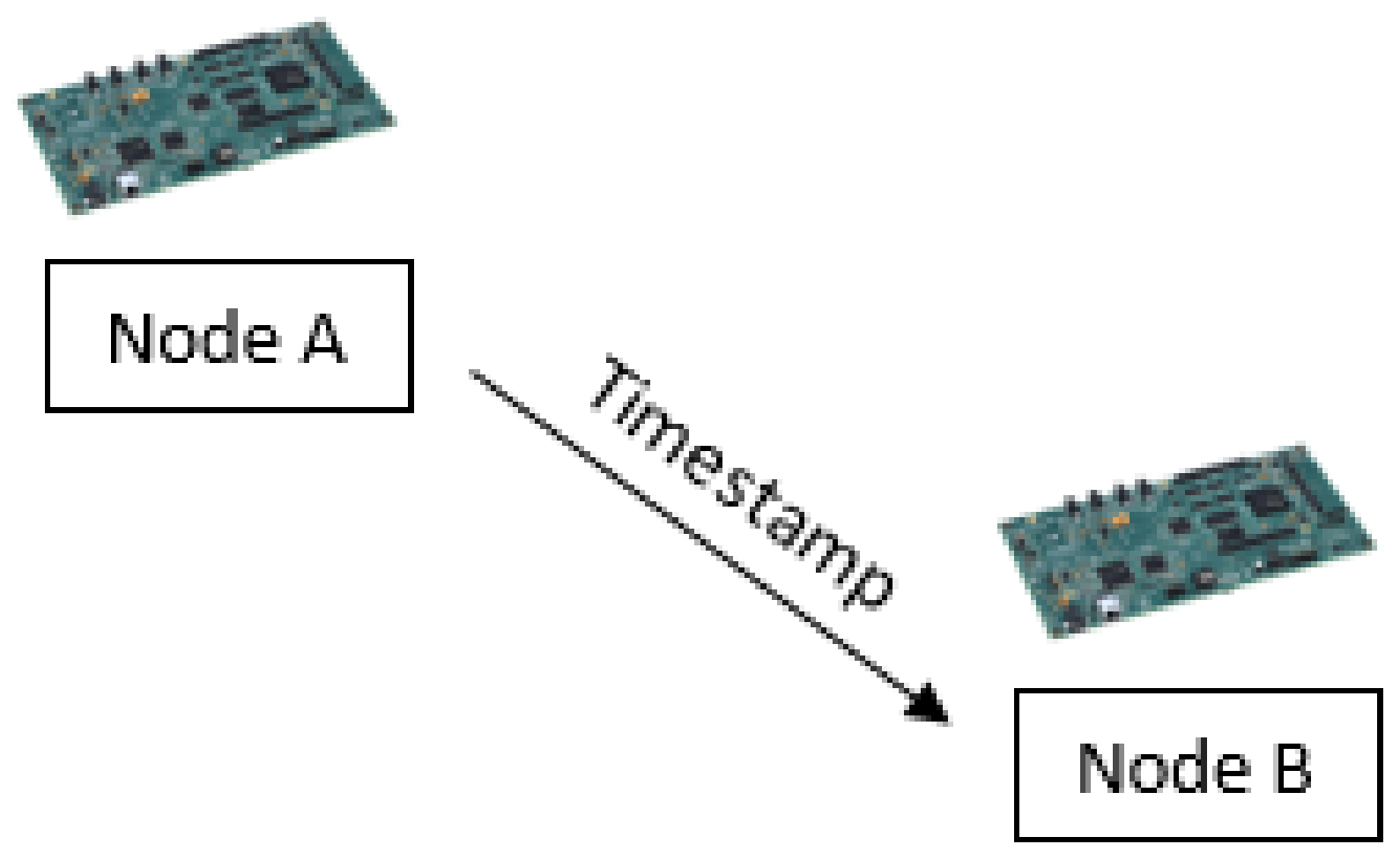
The whole process of STSC can also be explained with the help of flowchart shown in
Figure 2. At the application layer of node A, a software clock is used to generate a timestamp. That timestamp representing the time of node A is packed into an STSC packet, which is eventually sent over the medium with the help of the physical layer. The physical layer deals with all the transmission details such as the modulation scheme, data rate, etc. This packet is transmitted to node B. At node B, the physical layer tries to recover the transmitted symbols which were affected during transmission. To recover the symbols, symbol timing recovery is conducted using multiple components. After passing the data from the matched filter, a timing error detector tries to extract the timing offset whereas a loop filter tries to track the error in real time [
26,
27]. On the computations of the loop filter, the interpolation control determines how to correct the upcoming symbols and instructs the interpolator accordingly. The output of the interpolation control specifically can adjust the time offset and is known as the fractional interval
. Applying the least squares (LS) method to the output of the interpolation control leads to the skew estimation. This skew is used to correct and synchronize the time skew of node B’s clock. The output of the interpolator, which consists of the received symbols, contains the clock value of node A and hence can be used to correct the time phase error of node B’s clock. Once the time phase and skew are corrected, the clock is synchronized with the clock of node A.
4. Mathematical Analysis
Mathematically, the software clock can be defined as,
where
t is the time and
is the angular frequency of the oscillator of the hardware clock [
17,
18,
20]. If we simplify, then the software clock can be written as
where
is the phase and
s is the frequency of the software clock
. Using Equation (
2), the software clocks
and
for two synchronizing nodes A and B can be written as
The stimestamp received from node A to node B have the phase
included as the content of the message and hence, it is known at node B. Node B also knows its own phase
because it simply reads the content from its own clock. The timing phase difference
can now be computed as
or
Once node B knows about the phase offset and , it adds these two quantities to synchronize its own clock. Hence, which the synchronized phase of node B.
Now, for the computation of the skew offset, the output of the matched filter
is fed to the interpolator to find the
kth interpolant that is defined as
where
is the fractional offset column vector of n elements and
represents the
kth element of the vector. If we apply the least squares method [
28], we can find the skew offset
and
c as
where
S are the received samples and
c is a constant.
is the skew computed after achieving synchronization. The synchronized clock of node B can now be written with the help of Equations (
4), (
6), and (
8) as
Hence, the fractional interval leads to the skew offset computation and can be applied to the computation of the software clock for synchronization.
The STSC method also optimizes the energy utilization of the V2X systems. By using one STSC packet, the energy required to synchronize is just the energy required to transmit a single timestamp. It can be mathematically written as
where
is the energy per bit and
is the number of bits in one packet. However, if any other time synchronization protocol is used, then it requires multiple timestamp exchanges in order to compute the clock skew. The energy required for such protocols can be written as
where
is the energy required for multiple-timestamp protocols and
is number of timestamps exchanged to compute the skew.
Now, the efficiency
can be computed as
By using Equations (
10) and (
11), we have
Hence, theoretically this STSC approach increases the efficiency by
times. In this paper, we considered an efficient STSC for the time synchronization in V2X networks to estimate the time skew at the hardware level with the help of a physical-layer time synchronization using symbol timing recovery. In the future, the proposed STSC technique can be extended to the synchronization of a whole network of nodes as in [
29,
30] and to the synchronization of scenarios such as task offloading in mobile edge computing as in [
31,
32], which will be a good way forward for upcoming research articles.
5. Implementation and Results
The proposed idea was implemented on two floating-point DSP TMDSDSK6713 kits (DSK) manufactured by Texas Instruments. These kits provided low-cost development platforms and could be used for the implementation of physical-layer concepts such as symbol timing recovery. These kits acted like network nodes. There were two nodes in the implementation scenario, as shown in
Figure 3.
Hence, two DSP kits were used as node A and node B. The hardware clock of both kits had a known time skew of around 3
s. However, this skew needed to be computed in wireless systems and was not already known. Node A had to synchronize in time with node B. Thus, node A sent a timestamp to node B. That timestamp included the sender’s clock, which was used by the receiving node B to remove the clock phase offset. For the correction of the clock skew offset, node B extracted the time skew of the hardware clock using symbol timing recovery.
Figure 4 shows the procedure adopted for receiving a timestamp at the physical layer, finding the skew, and applying it to the software clock of node B.
When two nodes try to synchronize at the physical layer, the received packet must undergo a symbol timing recovery [
33,
34]. One such system using PLL was used here. The symbols received in timestamp packets were binary PAM symbols. These symbols passed through the interpolator, timing error detector, loop filter, and interpolation control. A zero-crossing timing error detector (ZC-TED) was used to detect the timing error with the help of symbol values crossing at the zero level [
35]. The loop filter tried to track the timing error detected by the ZC-TED. The interpolation control instructed the interpolator to change the sampling instant so that the next sample could be received with less error. Every next symbol error was detected, tracked, and the sampling instant kept changing until it completely tracked the error. These components were implemented for the computation of the fractional offset present between the sender and receiver clocks [
33]. The output of the interpolation control was the fractional interval
, which is a very important signal for extracting the time skew.
The output of the matched filter is shown in the eye diagram in
Figure 5. The received symbols had a timing error. When that error was tracked using the symbol timing recovery method, the output of the interpolator was synchronized in time and the corresponding eye diagram is shown in
Figure 6. This eye diagram shows that the PAM symbols were simply recovered. The scatter plot before (
Figure 7) and after the timing recovery (
Figure 8) also shows that without time synchronization, no pair of wireless nodes could communicate with each other.
The plot of the fractional offset
is shown
Figure 9. This offset converged to one point and the least squares (LS) method was used to obtain the time skew. Applying the LS method to the fractional offset produced the graph shown in
Figure 10. Hence, the computed output shows that the hardware clock skew offset was −3.1581
s. Keeping this in mind, we then considered the software clocks running on node A and node B. Some of the values of both clocks are shown in
Table 1. These values were 1000 ticks apart. For the first value, we computed the phase offset which was 19,000 and could be corrected by the timestamp packet. Considering one tick of the software clock was 1000 ticks of the hardware clock, the skew of the software clock was computed and yielded
= 3 ms. The skew of the hardware clock computed by the STSC approach was 3.1581
s and after translation to the software clock’s skew, it was 3.1581
× 1000 ticks = 3.1581 ms, which was approximately the same as that computed above. Hence, the software clock derived from this hardware clock had the same offset. The skew of the software clock could be adjusted using that offset and once done, the clocks were synchronized in frequency and the contents of the timestamp packet was used to synchronize in phase. The software and hardware clocks of the sender and receiver were then in synchronization using a single timestamp, as described for the STSC method.
The experiment was conducted again using two different DSKs with a known offset of around 3
s. The STSC method computed the skew estimate for the new nodes, which was 3.2183
s, as shown in
Figure 11 and
Figure 12.
To further strengthen the experimental results, the experiment was conducted a third time using two different DSKs with a known offset of around 20
s. The STSC method computed the skew estimate for the new nodes as 20.907
s, as shown in
Figure 13 and
Figure 14.
In the literature, many different state-of-the-art time synchronization protocols, such as, flooding time synchronization protocol (FTSP), timing-sync protocol for sensor networks (FTSP), timestamp synchronization (TSS), and lightweight time synchronization (LTS) at the application layer were discussed in the related work section. All these protocols used a multiple-timestamp exchange in order to calculate the skew of the clock. They tended to decrease the message exchanges by either incorporating timestamps in the data package (e.g., TTS), creating a spanning tree of the network nodes following a centralized algorithm (e.g., LTS), or using a level hierarchy (TPSN). Still, the timestamp exchanges required were more than one in the mentioned and other available protocols. In the STSC, only one timestamp was enough for the synchronization at the physical and application layers and for estimating the clock skew. For example, the FTSP synchronized two nodes with two timestamps, compared to the STSC method, which could synchronize with one timestamp, doubling the efficiency theoretically. In contrast to existing works, the proposed STSC approach was applied between any two nodes of the V2X system, and the time synchronization could be achieved with one timestamp packet, hence saving the transmission and computational energy required to send multiple timestamps.


