Article

An Intelligent Human-like Motion Planner for Anthropomorphic Arms Based on Diversified Arm Motion Models

College of Vehicle and Traffic Engineering, Henan University of Science and Technology, Luoyang 450052, China
Electronics 2023, 12(6), 1316; https://doi.org/10.3390/electronics12061316
Submission received: 5 February 2023 / Revised: 3 March 2023 / Accepted: 8 March 2023 / Published: 9 March 2023

Abstract

:
In this paper, the human-like motion issue for anthropomorphic arms is further discussed. An Intelligent Human-like Motion Planner (IHMP) consisting of Movement Primitive (MP), Bayesian Network (BN) and Coupling Neural Network (CPNN) is proposed to help the robot generate human-like arm movements. Firstly, the arm motion model is decoupled in the aspects of arm structure and motion process, respectively. In the former aspect, the arm model is decoupled into different simple models through the Movement Primitive. A Hierarchical Planning Strategy (HPS) is proposed to decouple a complete motion process into different sub-processes. Based on diversified arm motion models, the Bayesian Network is used to help the robot choose the suitable motion model among these arm motion models. Then, according to the features of diversified arm motion models, the Coupling Neural Network is proposed to obtain the inverse kinematic (IK) solutions. This network can integrate different models into a single network and reflect the features of these models by changing the network structure. Being a major contribution to this paper, specific focus is on the improvement of human-like motion accuracy and independent consciousness of robots. Finally, the availability of the IHMP is verified by experiments on a humanoid robot Pepper.

1. Introduction

As the application of robots is growing closer to humans, higher requirements for robots are put forward. Human-like motion is one of the important issues, especially for humanoid service robots, advanced industrial robots, and assistive robots [1]. The future advanced industrial robot is a potential application area. Although industrial robots are developing in the direction of intelligence [2,3], their tasks are relatively simple. Unlike the tasks of traditional industrial robots, the tasks of anthropomorphic arms are more complex and various. In addition, more and more anthropomorphic arms work with humans and even can be the companion of humans. They can work in the spaces ergonomically designed for human workers and are safe enough to work together with human workers [4]. Generating human-like movements can also help assistive robots, such as the wearable exoskeleton robots, to support or enhance natural body movements for disabled people [5]. Some rehabilitation robots have been on the market. Currently, the new trends in robotics research have been denominated service robotics because of their general goal of moving robots closer to human social needs [6]. The humanoid robot is an important branch in service robotics. People hope that these robots are human-like not only in their structures but also in their intelligence and movements [7]. Anthropomorphic arms provide humanoid robots a powerful manipulation ability. Except for the anthropoid shape, humans prefer that anthropomorphic arms have the manipulation ability of humans. During Human Robot Interaction (HRI), the human-like motions of anthropomorphic arms can increase not only the comfort and security of the users but also the efficiency of HRI. Thus, research of human-like motion determines whether the humanoid robots meet the requirements of the tasks in HRI.
The key issue is to generate anthropoid arm postures [8]. The methods are mostly classified into two categories: index optimization and feature extraction. The former predicts arm postures by optimizing the Human Performance Measures (HPMs). The early HPM is mainly based on psychophysical discomfort [9,10]. This HPM indicates that the farther from the center angle, the more uncomfortable humans feel. In addition, some HPMs such as maneuverability [11], minimal effort [12], obstacle avoidance [13] and joint limits [14] are used to evaluate the human-likeness. As research continues, other HPMs are extracted through different disciplines. Colim et al. [15] used the rapid upper limb assessment (RULA) from ergonomic researches to analyzes an industrial implementation of a collaborative robotic workstation. Rosell et al. [16] proposed the concept of “principal motion directions” to reduce the dimension of the search space to obtain results with a compromise between motion optimality and planning complexity. Mainly inspired from established theories of human motor control, Gulletta et al. [17] presented a human-like upper-limb motion algorithm to generate collision-free trajectories with human-like characteristics. The later predicts arm postures by extracting the features of human arms. Asfour et al. [18] used a stereo vision to capture the feature points of human arms, and employed the Hidden Markov model to learn the statistical features of the Cartesian trajectories and achieve tasks. Tomić et al. [19] presented a conversion process for the imitation of human arm motion by a humanoid robot. The conversion process consists of an imitation algorithm and an algorithm for generating the human-like motion of the humanoid. Given that natural human movement exhibits several robust features, Maurice et al. [20] examined whether human–robot physical interaction is facilitated when these features are considered in robot control. Results showed that the applied force was significantly lower when the robot moved with a biological velocity pattern. Gielniak et al. [21] proposed a three-stage pipeline to improve the clarity of robot motion by making it more human-like. Yang et al. [22] proposed a fuzzy control scheme to solve the dual-arm robot control with uncertain kinematics and dynamics. To make the robots engage in physical collaboration with humans, Noohi et al. [23] proposed a model to compute the interaction force during a dyadic cooperative object manipulation task. Whether they are based on index optimization or feature extraction, the methods ignore the influence caused by arm models. In fact, human arm movements are complex [24]. During the movement, arm states are changing constantly. Different numbers and combinations of joints form different arm states [25]. Human arms can perform different and complex tasks by coordination and cooperation of different joints. Thus, the arm motion models are diversified.
Due to the diversity of arm motion, how to select a proper motion model among different models becomes an important issue. Many basic methods have been employed in the research of robot decision-making [26]. Perula–Martinez et al. [27] proposed a decision-making system for social robots that prefers to engage them in the interaction. Huang et al. [28] combined the traditional drift diffusion model and the null-space-based behavioral control method to build a human decision-making behavior model for HRI. Fu et al. [29] proposed a group decision-making methodology for handing multiple criteria robot selection problem. To mitigate the burden on humans in conventional surveillance systems, Witwicki et al. [30] proposed an architecture for an intelligent surveillance system. The integration of components in this system supports fully automated decision-making. Due to its unique strengths both in inference and in visualization, the BN is widely used in the field of robotics [31,32]. Artemiadis et al. [33] described the dependencies among the human joint angles using a BN. Magnenat et al. [34] proposed a learning-form-demonstration framework based the BN. This framework combines the demonstrated commands according to the similarity between the demonstrated sensory trajectories and the current replay trajectory. Combined with the characteristics of the decision-making of a soccer robot, Liu [35] analyzed the role transformation and experience sharing of multi-agent reinforcement learning, and applied it to the local attack strategy of a soccer robot, and used this algorithm to learn the action selection strategy of the main robot in the team.
The most direct method to generate human-like movements is solving the IK of anthropomorphic arms. However, traditional IK methods have some inevitable drawbacks [36]. Additionally, the features of human arm movement lack clear physical interpretations. The analysis of inverse kinematics is complex. In most cases, it pursues multiple solutions. Furthermore, an analytic solution exists only for an ideal robot model when the structure of the robot meets certain conditions. How to choose the natural arm postures from the infinite postures at one target point is an important and challenging problem. Recently, most of the IK solutions are approached through the Artificial Neural Network (ANN). The ANNs can highly approximate the nonlinear function without knowing the specific physical interpretations. When the number of the samples is large enough, the ANNs are more accurate. Banga et al. [37] highlighted that feed-forward ANNs and Bees Back propagation via ANN were good means to solve IK problems and optimize the whole system. Toquica et al. [38] prosed a deep learning approximation model based on three different networks for the inverse kinematic problem of an industrial parallel robot. The network model is found and compared against a closed analytical form. Jiménez et al. [39] used an ANN composed of three hidden layers to solve the IK problem of a 3DOF open kinematic chain. The parameters of the traditional neural network are usually selected through the empirical and trial-and-error method, which may be biased and inefficient. Thus, Zhang et al. [40] proposed a broad neural network to approximate the unknown terms of the robots. This method can reuse the motion controller without relearning its weight parameters.
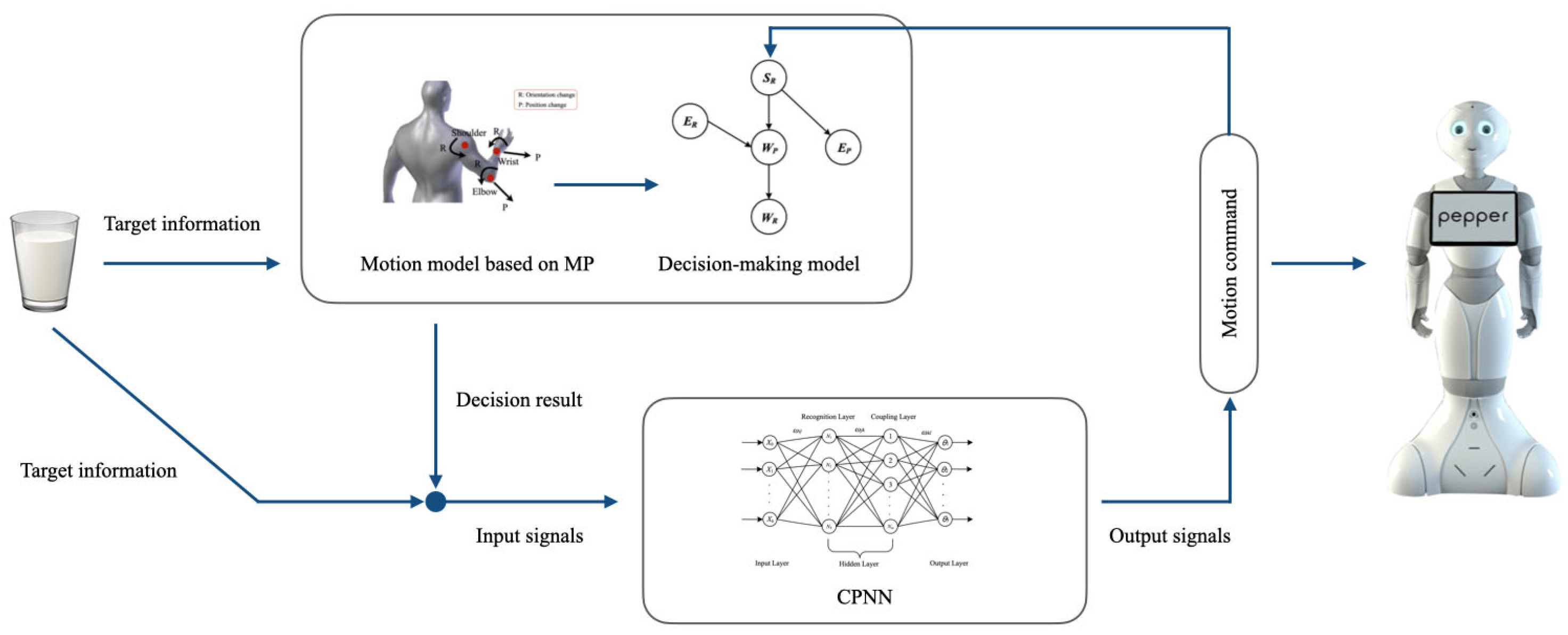
In previous work, we built a simple arm motion model based on movement primitives. The Bayesian network was used to choose the MP. A mixed IK algorithm, including the method based on geometrical constraints and the method based on index, was proposed to solve the IK problems. However, we ignored the influence caused by the motion process. The mixed IK algorithm cannot satisfy the accuracy requirement due to the diversity of arm motion models. Thus, in this paper, further studies have been conducted based on the previous work. The contribution of this paper is proposing an IHMP for anthropomorphic arms to improve the accuracy and efficiency of human-like arm movements. With the IHPM, the robot can generate the human-like arm movements accurately and autonomously. To achieve this purpose, a diversified arm motion model is proposed to represent different human arm movements. The robot can mimic various human-like movements using this model. Although the diversified motion models can approximate the real human arm movements, how to choose a proper motion model among different models is very critical. Thus, the BN is used to help robot predict and determine the motion. The motion variables are extracted and the conditional dependencies in different models are built. With this decision-making model, the robot can choose the appropriate way of moving automatically. Finally, an IK method, CPNN, is proposed to generate the joint trajectories of anthropomorphic arms fast and accurately. Through the CPNN, the diversified motion models can be integrated into a single network and their features can be reflected by changing the network structure. The structure of the IHMP is shown in Figure 1.
The remainder of this paper is organized as follows: In Section 2, the diversified arm motion model is introduced. The decision-making method to help robot choose the suitable model is described in Section 3. The corresponding IK method to solve the IK problems is shown in Section 4. Section 5 shows the results of experiments. Section 6 concludes the paper.

2. Arm Movement Decoupling

The mechanism of human arm movement is highly complex, and its movement mainly relies on joints. Various complex movements are completed through the coordination of different joints. At the same time, different exercise modes and environmental constraints also impact arm movement. Therefore, in this paper, arm structure and its movement are analyzed separately to decouple arm movement.

2.1. Decoupling the Arm Structure

Neurophysiological research has shown that the movement of vertebrates and invertebrates is composed of movement primitives [41]. As shown in Figure 2, the human arm can be divided into the shoulder joint, elbow joint and wrist joint according to the serial structure of the physiological joints. Each physiological joint has two properties: orientation attribution (R) and position attribution (P). The orientation attribution represents the change in the orientation of the physiological joint relative to the previous joint. The position attribution represents the change in the position of the physiological joint relative to the world coordinate system. A change in the orientation attribution of the previous joint will affect the change of the position attribution for the latter joint. When a change in the position attribution of the current joint does not affect the position attribution of the latter joint, a generational influence will occur, that is, the position attribution of the subsequent joint changes. When planning the motion of anthropomorphic arms, the shoulder joint is often immobile. Therefore, the world coordinate system is established at the shoulder joint so that it only has the orientation attribution.
Table 1 shows the eight MPs for the arm during its movement process when the end position changes. S, E and W represent shoulder, elbow and wrist joints, respectively. The symbol “ ⇒ ” indicates a driving relationship, i.e., the former drives the latter. The symbol “ → ” indicates that the latter is the accompanying movement of the former. The symbol “;” is used to distinguish two active drive elements. Taking the MP SREPRWP as an example, we briefly introduce the physical meaning of the MPs in Table 1. S + E implies that the shoulder and elbow joints are the driving joints, and their orientation attribution has changed. SREP indicates that the change of the orientation attribution of the shoulder joint affects the position attribution of the elbow joint. ERWP indicates that the change of the orientation attribution of the elbow joint affects the wrist joint position attribution.

2.2. Decoupling the Movement Process

According to the different exercise modes and environmental constraints of the anthropomorphic arms, the same MP has different motion modes. A Hierarchical Planning Strategy is used to decouple the movement process. As shown in Figure 3, the HPS consists of two decision conditions (distance decision and orientation decision) and three planning levels (first level, second level, and third level). From the perspective of motion planning, the decision conditions decompose the movement process into different sub-movement stages. Each stage corresponds to a different planning layer, and each planning level contains different MPs.

2.2.1. Decision Conditions

During human arm movement, there are some key arm postures that often occur at the beginning or end of different movement stages [42]. The purpose of determining the decision conditions is to accurately divide these stages.
1.
Distance decision condition
Speed is an important factor affecting arm motion. In biomechanics, extensive researches have been performed on human arm speed and joint angular speed [43]. Based on this, the threshold value of the distance decision condition can be obtained as follows:
Δ E p = v t w r i s t = d t w r i s t / ( a + b log 2 ( 2 d / W ) )
where twrist is the wrist joint movement time, a and b are regression coefficients, d is the distance from the initial point of the wrist to the target center point, and W is the width of the target area.
During the movement, when the arm end position P and the target position Pgoal meet the following conditions, the distance decision condition is triggered as follows:
Δ P = P P g o a l Δ E P
2.
Orientation decision condition
Through the human arm movement experiments, it is found that when the hand orientation is close to the target orientation during the movements, the hand orientation will remain unchanged for the following movements. Therefore, the orientation decision condition is mainly used to determine the relationship between the target orientation and the hand orientation during the movements. Through the experimental method, the threshold of orientation change during the movements can be obtained. Table 2 shows the extreme orientation difference in different directions measured in the experiments. Considering the error factor and the influence of different directions on the result, the threshold of the orientation decision condition can be set as follows:
Δ R = n Δ R ^
where n represents the weight coefficient, and the value range is [0.5, 1]; R ^ is the orientation difference.
During arm movement, when the orientation R and target orientation Rgoal meet the following condition, the orientation decision condition is triggered as follows:
Δ R = R R g o a l Δ E R

2.2.2. Planning Layer

Different from the MPs that divide motion based on arm structure, the HPS decouples the motion process based on environmental constraints. The planning layer subdivides the MPs. The same MP can appear in different planning layers. Although the arm structure has not changed, the motion modes differ according to different constraints. First-level planning describes the reaching process. There is no need to consider the orientation of the wrist, and the movement of the wrist is presented in the form of follow-up. Second-level planning describes the grasping process. Here, the wrist movement plays a leading role during the movements and determines the quality of the completed task. Third-level planning describes a special type of movement in that when the hand orientation is close to the target orientation during the movements, the arm will complete the entire movement while keeping the hand orientation unchanged.

2.3. Motion Model Based on Decoupling the Human Arm

The MPs and HPS complete the decoupling of human arm movement. Figure 4 shows the motion models based on human arm decoupling. According to the movement characteristics of different planning layers, the MPs are divided. After division, each MP considers the characteristics of the constraints and its own structure so that the movement is more refined.

3. Decision-Making Model

Through the HPS-MP motion models, the human arm motion is divided into different MPs, and different MPs thus lead to different forms of motion. In actual movements, the anthropomorphic arm needs to choose the suitable motion models to complete a variety of operational tasks. In this paper, we use the powerful reasoning ability of the Bayesian network to establish a decision-making model.

3.1. Motion Variables

MPs are composed of movement elements, and different combinations of movement elements constitute different MPs. Therefore, the process of selecting MPs is the process of selecting and reorganizing movement elements. Five movement elements (SR, EP, ER, WP, WR) are used as motion variables to establish a BN. According to the arm tree structure, there is a direct causal relationship between the movement elements. According to the collected human arm movement data, the prior probability of each motion variable can be obtained, thereby obtaining the conditional probability between the variables. Each motion variable satisfies the exponential distribution, and its parameters are different according to the attributes of the variable. Among the motion variables, EP and WP are functions of distance. WP is related to the absolute value of the difference between the distance from the shoulder to the target position and the distance from the shoulder to the wrist. EP is related to the absolute difference between the distance from the elbow to the target position and the forearm length. The motion variables SR, ER and WR are functions of the target orientation. Therefore, the Exponential Probability Density Function (EPDF) is used to calculate the occurrence probability of each motion variable. Each motion variable has a corresponding EPDF, and its parameter λ can be calculated by the maximum likelihood estimation and through the leave-one-out cross-validation method for verification. According to the probability distribution of each motion variable, the dependency between the variables can be calculated according to different constraints.

3.2. Network Strucure

The BN is a graphical model used to express the connection probability between different variables. It comprehensively considers prior information and sample data, and combines expert opinions and experience to analyze the problem quantitatively and qualitatively. The network structure is a directed acyclic graph consisting of variable nodes and directed edges connecting these nodes.
According to HPS, when planning the motion of the anthropomorphic arm, it is first necessary to determine the appropriate planning layer according to the constraints, and then select the appropriate MP according to the selected planning layer. Therefore, according to the law of MP construction and the motion characteristics of each planning layer, we established the BN structure under three different planning layers as shown in Figure 5.

3.3. Decision Algorithm

The mutual information index can be expressed as the total amount of information dependence during the movements. The dependency relationship between motion variables at a certain moment is needed. Therefore, the transient mutual information (TMI) index is proposed in this paper:
I ^ ( X , Y ) = P ( x , y ) log P ( x , y ) P ( x ) P ( y )
where P(x,y) is the joint probability distribution function, and P(x) and P(y) are the marginal probability distribution functions. The probability function is the objective prior probability, and the data are collected from the experiments of human arm movement.
Similarly, the Transient Conditional Mutual Information (TCMI) index can be expressed as follows:
I ^ ( X , Z | Y ) = P ( x , y , z ) log P ( x , y , z ) P ( y ) P ( x , y ) P ( z , y )
At the same time, the mutual information reflects the dependence between two variables, and the composition of MPs is generally composed of more than two motion variables. Therefore, the Accumulative Mutual Information (AMI) index is proposed as the selection criterion of the MPs. According to the joint nodes represented by the motion elements, the AMI is divided into series and parallel. The serial type can be defined as follows:
I s ( x 1 , x 2 , x i ) = I ^ ( x 1 , x 2 ) + I ^ ( x 2 , x 3 ) + + I ^ ( x i 1 , x i )
where vi represents the motion variables of different nodes. The parallel type can be defined as follows:
I s ( x 1 , x 2 , x i ) = I ^ ( x 2 , x 3 | x 1 ) + + I ^ ( x 2 i + 1 , x 2 i | x 2 i 1 )
where v2i+1 and v2i represent different attributes under the same node.
According to the Equations (7) and (8), the AMI value of the MPs under each network structure can be determined. For example, the AMI value of MP SREPWP in first-level planning is the following:
g 1 = I s ( S R , E P , W P ) = I ^ ( S R , E P ) + I ^ ( E P , W P ) = P ( S R , E P ) log P ( S R , E P ) P ( S R ) P ( E P ) + P ( E P , W P ) log P ( E P , W P ) P ( E P ) P ( W P )
In different planning layers, the corresponding gi (i = 1, 2, 3, 4) of each MP is used to calculate its AMI value. Therefore, an objective function G t m is defined as follows:
G t m = max { g 1 m , g 2 m , g 3 m , g 4 m } , m = 1 , 2 , 3
where G t m is the objective function and m represents different planning levels. After determining the planning level m, corresponding gi can be calculated. The objective function G t m selects the largest element gi. In this way, the decision-making problem is transformed to maximize the objective function G t m , and the selected element gi is the result of this decision.
Figure 6 shows the flow chart of the motion decision algorithm. After determining the path points at the beginning and end states, the robot makes a decision on each path point. First, the appropriate planning layer is selected through HPS. Second, the AMI value of each MP is calculated according to the selected planning layer. Then, the maximal g in objective function G t m is selected. The selected corresponding MP is the decision result. The robot will then use this MP as the motion mode. Finally, the robot calculates the IK solutions through the IK algorithm to obtain the joint angles and performs the operation.

4. Inverse Kinematic Solution

The variability of arm models will have a great impact on calculation efficiency and increase the amount of calculation required to solve joint angles. Nevertheless, the traditional IK methods have inevitable defects. Because ANNs can highly approximate the nonlinear functions, ANNs are widely used in solving IK problems of manipulators. However, for the anthropomorphic arm, a single neural network model cannot accurately reflect the varying characteristics of the human arm model, and parallel neural networks will further complicate the network structure and increase the amount of calculation. Therefore, we used the Coupling Neural Network to solve the IK problem.

4.1. Coupling Neural Network

Figure 7 shows the network structure of CPNN. The network includes one input layer, two hidden layers, and one output layer. The input signal in the input layer contains the target information, including target position and orientation. The hidden layer is composed of two sub-layers: the recognition layer and the coupling layer. Each sublayer in the hidden layer has its own function. In the recognition layer, the neuron Ni represents five motion variables and three planning layers, respectively. The values of the Ni can be seen in the Table 3. Its function is to determine the results of the decision-making algorithm. According to different decision results, the recognition layer changes the structure of the network. The main function of the coupling layer is to calculate the anthropomorphic arm joint angles under different network structures. These two hidden layers together realize the diversity of CPNN. The neurons in the output layer divide the mechanical joints represented by the neurons into shoulder joints, elbow joints, and wrist joints according to the physiological joints. Each joint set is composed of several mechanical joints. In the coupling layer, Sh, Ek, and Wm represent the neurons. According to different output items, the mapping area is also divided into three sub-areas ([S1, Sh], [Eh+1, Ek] and [Wk+1, Wm]). Different Ni activates different neurons in the three sub-regions. When Ni is determined by the decision-making algorithm, the corresponding hidden layer neuron in the mapping area will be activated and participate in the mapping calculation. The diversity of CPNN imparts several advantages for solving the IK problem of diversified anthropomorphic arm.

4.2. Coupling Neuron

Figure 7 shows that in the coupling layer, some hidden layer neurons activated by different Ni overlap, such as S4 being activated by N1 and N2 at the same time. In other words, their corresponding weights are the same, so the output calculated by the weight accumulation and calculation is also relatively close, and this type of neuron is called coupling neurons. The characteristic of the coupling neuron is that it can be activated by multiple Ni simultaneously, which can improve the convergence speed and generalization ability of the network. The coupling coefficient C represents the number of Ni that activates the same coupling neurons. When the coupling coefficient is 1, it indicates that the coupling neurons are activated by two (C+1) Ni at the same time. In this section, the coupling coefficient is 1 by default.
The number of coupled neurons is closely related to the number of hidden neurons in the coupling layer. The number of hidden layer neurons in the coupling layer can be expressed as follows:
M ( M t 2 , M t ) M t = 1 i M i
where M represents the number of hidden layer neurons in the coupling layer, and I is the number of MPs that CPNN can reflect. These models can reflect their mapping relationship through a single BP neural network according to their different input and output combinations. Mi is the number of neurons in the hidden layer of a single BP neural network that satisfies the input and output relationship, which can be obtained by the following:
M i = n o
where n is the number of neurons in the input layer of the BP neural network, and o is the number of neurons in the output layer of the BP neural network.
Therefore, the number of coupling neurons M can be obtained by the following:
m = M t M , C = 1
According to the coupling neuron equation, the number of coupling neurons can be set in advance based on the number of models input by the network to determine the number of hidden layer neurons in the network. At the same time, the hidden layer structure of the network can be set in advance to calculate the number of coupling neurons. The former can be used to adjust the structure of the network, and the latter can be used to control the overall calculation of the network.

4.3. Network Training

After the determination of the network structure, the CPNN is trained. There are 2400 sets of generated data (-ERWP, △-ERWPR, -SRWP, -SRWPR, □-ERWPR and □-SRWPR has 100 sets, respectively, and each of rest of the primitives has 300 sets, respectively), of which 70% is used for training, 15% for validation and 15% for testing. The data are collected by motion capture system and used as the network input.
The network input X(t) is the following:
X ( t ) = [ X 0 , x d ( t ) , y d ( t ) , z d ( t ) , α d ( t ) , β d ( t ) , γ d ( t ) ]
where x, y and z represent the desired position of the target, and α, β and γ are the Euler angles and represent the desired orientation of the target. Through the motion capture system, these values can be collected as the input values. X0 is the reference output item used to activate the neurons in the recognition layer and its value is determined by the decision-making algorithm. Table 3 shows the different combinations of X0.
In this paper, the sigmoid function is used as the transfer function between the layers, and the output of the recognition layer can be expressed as follows:
h j ( t ) = X 0 1 + e s j ( I j ( t ) ) , j = 1 , 2 , 3 ... , 8
Among them, the input of the recognition layer is the following:
I j ( t ) = i = 1 6 w i j ( t ) X i ( t )
where ωij(t) is the weight coefficient between the i-th neuron in the input layer and the j-th neuron in the recognition layer, and sj is the slope of the neuron’s sigmoid function of the j-th neuron in the recognition layer.
The output of the coupling layer can be expressed as the following:
h k ( t ) = 1 1 + e s k I k ( t ) , k = 1 , 2 , 3 , , m
where the input of the coupling layer is the following:
I k ( t ) = j = 1 m w j k ( t ) h j ( t )
where ωjk(t) is the weight coefficient between the j-th neuron in the recognition layer and the k-th neuron in the coupling layer, and sk is the slope of the sigmoid function of the k-th neuron in the coupling layer.
The final output of CPNN θl(t) is the following:
θ l ( t ) = k = 1 m ω k l ( t ) h k ( t ) o r θ l ( t 1 )
It should be noted that due to the different input and output combinations caused by the multi-model problem, not all joint angles are obtained from the network output in the same model. Therefore, these remaining joint angles will be obtained from the anthropomorphic arm’s previous motion state.
To train the CPNN, we define an error function as the following:
E ( t ) = 1 2 i = 1 6 ( e i ( t ) ) 2
where ei(t) represents the difference between the expected orientation of the network and the actual output orientation.
e 1 t = x d t x a t e 2 t = y d t y a t e 3 t = z d t z a t e 4 t = α d t α a t e 5 t = β d t β a t e 6 t = γ d t γ a t
when the actual output of the network is not equal to the expected output, there will be an output error E(t). The error function represents the error sum of the position and orientation in the anthropomorphic arm working space and can be calculated from the joint angle obtained by the network output. The network error is a function of the weight coefficients of each layer; therefore, the weight coefficients are adjusted through the error back propagation to improve the error. The principle of adjusting the weight coefficient is to continuously reduce the error; consequently, adjusting the amount of the weight coefficient is proportional to the gradient of the error. The gradient of the error function can be expressed as the following:
E ( t ) ω k l ( t ) = e 1 ( t ) x a ( t ) ω k l ( t ) e 2 ( t ) y a ( t ) ω k l ( t ) e 3 ( t ) z a ( t ) ω k l ( t ) e 4 ( t ) α a ( t ) ω k l ( t ) e 5 ( t ) β a ( t ) ω k l ( t ) e 6 ( t ) γ a ( t ) ω k l ( t )
For different MPs, the specific expression of each item in Equation (22) is also different. According to Table 4, the forward kinematic relations of the Pepper’s right arm can be obtained. Finally, the coefficient ω i j , ω j k and ω k l of each layer can be updated; we do not discuss this in detail in this paper.

5. Experimental Results

In this section, the availability of the proposed IHMP is also quantitatively evaluated and compared with other human-like planning methods with data collected from Pepper.

5.1. Experimental Setup

The humanoid robot Pepper is used as the platform to verify the effectiveness of the proposed algorithm. The arm configuration of the Pepper is shown in Figure 8. Each arm has five DOFs: three at the shoulder (shoulder abduction/adduction, shoulder flexion/extension and humeral rotation), one at the elbow (elbow flexion/extension) and one at the wrist (lower arm pronation/supination). Although Pepper’s arm only has five DOFs, it has obvious physiological joints and its arm configuration is similar to the human arm. The DH parameters of Pepper’s arm are shown in Table 4.
An OptiTrack motion capture system (Natural Point Inc., Corvallis, OR, USA) is used to capture the natural human arm postures when the subjects move their arms during the experiments. The motion capture system has six Prime X13 cameras, and their frequency is 100 frames per second. During the experiments, all the motion data of the subjects are recorded through the motion capture system, and these data are transformed into the model shown in Figure 8 through the BVH for comparison [44]. These collected data, as the measured results, are compared with the prediction results in the experiments. It must be noted that the configurations of the human arm and Pepper’s arm are different. Meanwhile, the individual differences between the subjects, such as height and arm length, will also affect results. Thus, the motion data captured by motion capture system should be normalized. The sailing method is used to transform these data [33].

5.2. Performance of Arm Posture Estimation

The experiments of drawing a circle are carried out to evaluate prediction performance of the proposed algorithm. Five subjects (three males and two females) with an average age of 20.2 voluntarily participate in these experiments. The subjects are asked to draw a circle on a virtual vertical wall. The equation of the circle on the wall is defined and the path of the circle is given. As shown in Figure 9, there are many points arranged in rows and columns on the virtual vertical wall, and the interval of every two points is 10 cm. The circle is given in the x–z plane of the cartesian coordinate systemin, and its trajectory is marked in red. The subjects stand 40 cm away in front of the wall. During the experiments, all the subjects are asked to hang their arms naturally as the initial arm postures. Each subject needs to complete the experiments five times to avoid error caused by the system and human factors. The arm motion data of all the subjects are collected by motion capture system as the measured results.
After the data transformation, these measured results collected by motion capture system are used to calculate the target positions and orientations through forward kinematics. Additionally, these joint angle data can be used for demonstration and learning, as described in Section 4. According to the target information, the predicted results can be obtained through proposed IHMP in this paper and compared with the measured results of the subjects. The indicator posture similarity S is used to evaluate the algorithm. The distance between a robot’s posture H and a human’s posture R is expressed as dist(R,H). The shorter the distance is, the greater the similarity is. The posture similarity S is defined as follows:
S ( R , H ) = 1 1 + d i s t ( R , H )
The value of S(H,R) is between (0,1). When dist(R,H) = 0, S(H,R) = 1, the similarity is the largest. The distance between the two postures can be expressed by the Euclidean distance in N-dimensional space. Thus, the dist(R,H) can be expressed as follows:
d i s t ( θ r , θ h ) = ( i = 1 N | | θ r i θ h i θ r i _ max θ r i _ min | | 2 ) 1 2
where θri and θhi are the i-th joint angles of robot and human, respectively. N is a dimension of joint space. [θri_min, θri_max] is the range of the i-th joint angle.
Figure 10 shows the similarity histogram of different subjects. There is a high similarity between the predicted results and the measured results. The variation trend (Mean = 0.9766, Standard Deviation = 0.0046) shows that our algorithm can satisfy the accuracy requirements of different subjects. The Euclidean Distance and Standard Deviation (SD) are also used to quantitatively evaluate the similarity of the joint angles. The definition of the Euclidean Distance is shown as follows:
D E ( L i , L j ) = 1 n k = 1 n m = 1 p ( a k m b k m ) 2
where Li and Lj are two different curves; n represents the length of the curve; p represents the dimension of the curve; a and b are the points on the two curves.
The detailed results of different subjects are shown in Table 5. It can be found that there is an obvious equivalence relationship between the predicted results and the measured results, which indicates the effectiveness of the proposed algorithm.

5.3. Anthropomorphic Motion Generation

To evaluate the effectiveness on real robots, the humanoid robot Pepper is required to follow the desired trajectories of the circle. According to the measured results above, the trajectories of the circle can be obtained. Pepper generates the human-like arm movements with a suitable motion model to complete the drawing task. Two highly accurate human-like motion algorithms, the minimum total potential energy (TPE) method [12] and the comprehensive method based on MP (CMMP) [45], are used to be compared with the proposed algorithm. The TPE is the method based on index. By optimizing the sum of gravitational potential energy and elastic potential energy, the robot can generate the human-like arm movements. In fact, the CMMP is an index-based method. The arm structure of robot is decoupled through the CMMP. Meanwhile, to verify the effectiveness of human-like motion algorithms, the nonhuman-like algorithm, the least norm algorithm (LNA), is also adopted to be compared with the human-like motion algorithms.
The similarity values of each subject are calculated, and the results of subject 2 are shown in Figure 11. The colors of different curves represent the similarity of different methods. The higher the values of the curve are, the more the predicted results approximate the measured results. It can be found the similarity of the human-like motion algorithms is significantly higher than the LNA’s results. We also compare the results of the TPE, the CMMP and the proposed IHMP. The detailed information is shown in Table 6. The similarity of the IHMP is higher than the other two methods. However, at some stages, the similarity of these three methods is very close. The reason is that the motion models of these three methods are similar at these stages. The TPE considers the arm model is unchanged during the movements, and ignores the diversity of arm models. Thus, although the TPE can obtain a high similarity at some stages, it cannot guarantee a high accuracy during the whole movement. The CMMP considers the diversity of arm models and decouples the arm structure. So, the accuracy of the CMMP is higher than the TPE. However, the CMMP ignores the influence of the environmental constraint. It cannot approximate the real arm models accurately. The errors of the CMMP are larger especially when the movements are more complex. As a result, it can be concluded that the IHMP has the stronger ability to handle the human-like arm movements with diversified arm models. The motion information of Pepper is shown in Figure 12.
After the experiments, five subjects are asked to grade the human-like motion of the Pepper in the experiments based on their sense of security and comfort. The results are shown in Table 7. The scores range from 1 to 5, and the higher scores indicate that the subjects feel safer and more comfortable. It can be shown that the scores of human-like motion algorithms are better than the scores of nonhuman-like motion algorithm. All the subjects indicate that they prefer to work with the robots who has the capacity to move like humans, which further shows the importance and necessity of the human-like motion algorithm.

6. Conclusions and Future Work

In this paper, an Intelligent Motion Planner is proposed to help anthropomorphic arms generate human-like arm movements. Three aspects of human-like motion including motion model, decision-making and IK problem are further studied. To improve the accuracy of human-like movements, the arm movements are decoupled into two aspects, arm structure and motion process. The arm model is decoupled into different simple sub-models based on MPs. Due to the influence of the environmental constraint, the same MP can show different motion patterns, which can decrease the accuracy of the human-like motion. Thus, the decoupling of the motion process needs to be considered. By combining these two ways, a motion model based on HPS-MP is proposed. This motion model has definite physical meaning, and reflects the inherent laws of human arm movements directly. With this model, the anthropomorphic arm can generate human-like movements accurately and fast.
A new decision-making model based on BN is constructed and can be applied to different planning levels. In this decision-making model, there are three network structures which can be applied to three planning levels, respectively, and each network is an independent sub-model. The probability of each HPS-MP can be obtained by calculating the AMI, so the decision problem will turn into the optimization problem. With the decision-making model, the anthropomorphic arm can choose an appropriate way to move automatically.
Finally, the IK problems can be solved through the CPNN. It is difficult for a single neural network to solve the IK problems of the diversified arm motion model. Although the parallel neural networks can approximate these different models, complex network structures will increase the difficulty of calculation. Meanwhile, in parallel neural networks, the identification of the diversified models is also a critical question. As a mutable network model, the CPNN can implement the mapping relation between the robot’s joints and diversified arm motion model, respectively. The availability of the IHMP is verified on a humanoid robot Pepper. The robot Pepper performs two groups of experiments. The experimental results show that the human-like arm motion of anthropomorphic arm can be solved effectively, and this performance is satisfactory.
In the future work, we hope to propose a novel online method based on the IHMP. Meanwhile, by using our method, the robot will perform more complex tasks and interact with humans. Additionally, future work will also focus on the application in HRI, such as robot driving and emotional expression.

Funding

This research is supported by the National Natural Science Foundation of China under Grant 51805149.

Data Availability Statement

Not applicable.

Conflicts of Interest

The authors declare no conflict of interest.

References

  1. Averta, G.; Della Santina, C.; Valenza, G.; Bicchi, A.; Bianchi, M. Exploiting upper-limb functional principal components for human-like motion generation of anthropomorphic robots. J. Neuroeng. Rehabil. 2020, 17, 63. [Google Scholar] [CrossRef]
  2. James, S.; Davison, A.J. Q-attention: Enabling efficient learning for vision-based robotic manipulation. IEEE Robot. Autom. Lett. 2022, 7, 1612–1619. [Google Scholar] [CrossRef]
  3. Katerina, M.O.; Ioannis, K.; Antonios, G. A Hybrid Spiking Neural Network Reinforcement Learning Agent for Energy-Efficient Object Manipulation. Machines 2023, 11, 162. [Google Scholar]
  4. Rodriguez-Linan, A.; Lopez-Juarez, I.; Maldonado-Ramirez, A.; Zalapa-Elias, A.; Torres-Trevino, L.; Navarro-Gonzalez, J.L.; Chinas-Sanchez, P. An Approach to Acquire Path-Following Skills by Industrial Robots from Human Demonstration. IEEE Access 2021, 9, 82351–82363. [Google Scholar]
  5. Hu, N.; Wang, A.; Wu, Y. Robust adaptive PD-like control of lower limb rehabilitation robot based on human movement data. PeerJ Comput. Sci. 2021, 7, e394. [Google Scholar]
  6. Liu, S.; Tian, G.; Zhang, Y.; Zhang, M.; Liu, S. Active Object Detection Based on a Novel Deep Q-Learning Network and Long-Term Learning Strategy for the Service Robot. IEEE Trans. Ind. Electron. 2021, 69, 5984–5993. [Google Scholar]
  7. Rossi, S.; Staffa, M.; Tamburro, A. Socially Assistive Robot for Providing Recommendations: Comparing a Humanoid Robot with a Mobile Application. Int. J. Soc. Robot. 2018, 10, 265–278. [Google Scholar] [CrossRef]
  8. Qu, J.; Zhang, F.; Wang, Y.; Fu, Y. Human-like coordination motion learning for a redundant dual-arm robot. Robot. Comput. Manuf. 2019, 57, 379–390. [Google Scholar] [CrossRef]
  9. Jung, E.S.; Choe, J. Human reach posture prediction based on psychophysical discomfort. Int. J. Ind. Ergon. 1996, 18, 173–179. [Google Scholar]
  10. Jung, E.S.; Kee, D.; Chung, M.K. Upper body reach posture prediction for ergonomic evaluation models. Int. J. Ind. Ergon. 1995, 16, 95–107. [Google Scholar]
  11. Storms, J.; Tilbury, D. Dynamic Weight-Shifting for Improved Maneuverability and Rollover Pretention in High-Speed Mobile Manipulators. J. Dyn. Syst.-Trans. ASME 2016, 138, 1–11. [Google Scholar]
  12. Zhao, J.; Xie, B.; Song, C. Generating human-like movements for robotic arms. Mech. Mach. Theory 2014, 81, 107–128. [Google Scholar] [CrossRef]
  13. Chen, Z.; Su, W.; Li, B.; Deng, B.; Wu, H.; Liu, B. An intermediate point obstacle avoidance algorithm for serial robot. Adv. Mech. Eng. 2018, 10, 1–15. [Google Scholar] [CrossRef] [Green Version]
  14. Ortenzi, D.; Muthusamy, R.; Freddi, A.; Monteriù, A.; Kyrki, V. Dual-arm cooperative manipulation under joint limit constraints. Robot. Auton. Syst. 2018, 99, 110–120. [Google Scholar] [CrossRef] [Green Version]
  15. Colim, A.; Morgado, R.; Carneiro, P.; Costa, N.; Faria, C.; Sousa, N.; Rocha, L.; Arezes, P. Lean Manufacturing and Ergonomics Integration: Defining Productivity and Wellbeing Indicators in a Human–Robot Workstation. Sustainability 2021, 13, 1931. [Google Scholar]
  16. Rosell, J.; Suarez, R.; Rosales, C.; Pérez, A. Autonomous motion planning of a hand-arm robotic system based on captured human-like hand postures. Auton. Robot. 2011, 31, 87–102. [Google Scholar] [CrossRef] [Green Version]
  17. Gulletta, G.; Silva, E.C.; Erlhagen, W.; Meulenbroek, R.; Costa, M.F.P.; Bicho, E. A Human-like Upper-limb Motion Planner: Generating naturalistic movements for humanoid robots. Int. J. Adv. Robot. Syst. 2021, 31, 87–102. [Google Scholar] [CrossRef]
  18. Asfour, T.; Azad, P.; Gyarfas, F.; Dillmann, R. Imitation learning of dual-arm manipulation tasks in humanoid robots. Int. J. Humanoid Robot. 2008, 5, 183–202. [Google Scholar] [CrossRef]
  19. Tomić, M.; Chevallereau, C.; Jovanović, K.; Potkonjak, V.; Rodić, A. Human to humanoid motion conversion for dual-arm manipulation tasks. Robotica 2018, 36, 1167–1187. [Google Scholar]
  20. Maurice, P.; Huber, M.E.; Hogan, N.; Sternad, D. Velocity-Curvature Patterns Limit Human–Robot Physical Interaction. IEEE Robot. Autom. Lett. 2017, 3, 249–256. [Google Scholar]
  21. Gielniak, M.J.; Liu, C.K.; Thomaz, A.L. Generating human-like motion for robots. Int. J. Robot. Res. 2013, 32, 1275–1301. [Google Scholar] [CrossRef] [Green Version]
  22. Yang, C.; Jiang, Y.; Na, J.; Li, Z.; Cheng, L.; Su, C.-Y. Finite-Time Convergence Adaptive Fuzzy Control for Dual-Arm Robot with Unknown Kinematics and Dynamics. IEEE Trans. Fuzzy Syst. 2018, 27, 574–588. [Google Scholar] [CrossRef]
  23. Noohi, E.; Zefran, M.; Patton, J. A Model for Human-Human Collaborative Object Manipulation and Its Application to Human-Robot Interaction. IEEE Trans. Robot. 2016, 32, 800–896. [Google Scholar] [CrossRef]
  24. Roitman, A.V.; Massaquoi, S.G.; Takahashi, K.; Ebner, T.J. Kinematic Analysis of Manual Tracking in Monkeys: Characterization of Movement Intermittencies during a Circular Tracking Task. J. Neurophysiol. 2004, 91, 901–911. [Google Scholar] [CrossRef] [PubMed]
  25. Pasalar, S.; Roitman, A.V.; Ebner, T.J. Effects of speeds and force fields on sub-movements during circular manual tracking in humans. Exp. Brain Res. 2005, 163, 214–225. [Google Scholar] [CrossRef]
  26. Darvish, K.; Simetti, E.; Mastrogiovanni, F.; Casalino, G. A Hierarchical Architecture for Human–Robot Cooperation Processes. IEEE Trans. Robot. 2021, 37, 567–586. [Google Scholar] [CrossRef]
  27. Perula-Martinez, R.; Castro-Gonzalez, M.; Malfza, M.; Alonso-Martín, F.; Salichs, M.A. Bioinspired decision-making for a socially interactive robot. Cogn. Syst. Res. 2019, 54, 287–301. [Google Scholar] [CrossRef]
  28. Huang, J.; Wu, W.; Zhang, Z.; Chen, Y. A Human Decision-Making Behavior Model for Human-Robot Interaction in Multi-Robot Systems. IEEE Access 2020, 8, 197853–197862. [Google Scholar] [CrossRef]
  29. Fu, Y.; Li, M.; Luo, H.; Huang, G.Q. Industrial robot selection using stochastic multicriteria acceptability analysis for group decision making. Robot. Auton. Syst. 2019, 122, 103304. [Google Scholar] [CrossRef]
  30. Witwicki, S.; Castillo, J.C.; Messias, J.; Capitan, J.; de Melo, F.A.C.S.; de Almeida Lima, P.M.U. Autonomous Surveillance Robots: A Decision-Making Framework for Networked Multiagent Systems. IEEE Robot. Autom. Mag. 2017, 24, 52–64. [Google Scholar] [CrossRef]
  31. Lotto, K.; Nagler, T.; Radic, M. Modeling Stochastic Data Using Copulas for Applications in the Validation of Autonomous Driving. Electronics 2022, 11, 4154. [Google Scholar] [CrossRef]
  32. Shi, H.; Lin, Z.; Zhang, S.; Li, X.; Hwang, K.-S. –An adaptive decision-making method with fuzzy Bayesian reinforcement learning for robot soccer. Inf. Sci. 2018, 436–437, 268–281. [Google Scholar] [CrossRef]
  33. Panagiotis, K.A.; Pantelis, T.K.; Kostas, J.K. A biomimetic approach to inverse kinematics for a redundant robot arm. Auton. Robots 2010, 39, 293–308. [Google Scholar]
  34. Magnenat, S.; Colas, F. A Bayesian tracker for synthesizing mobile robot behaviour from demonstration. Auton. Robot. 2021, 45, 1077–1096. [Google Scholar] [CrossRef]
  35. Liu, X. Research on decision-making strategy of soccer robot based on multi-agent reinforcement learning. Int. J. Adv. Robot. Syst. 2020, 17, 172988142091696. [Google Scholar] [CrossRef]
  36. Chaudhary, H.; Prasad, R. Intelligent inverse kinematic control of scorbot-er v plus robot manipulator. Int. J. Adv. Eng. Technol. 2011, 1, 158–169. [Google Scholar]
  37. Banga, R.; Kumar, Y.; Singh, Y. Fuzzy-genetic optimal control for robotic systems. Int. J. Phys. Sci. 2011, 6, 204–212. [Google Scholar]
  38. Toquica, J.S.; Oliveira, P.S.; Souza, W.S.; Motta, J.M.S.; Borges, D.L. An analytical and a Deep Learning model for solving the inverse kinematic problem of an industrial parallel robot. Comput. Ind. Eng. 2020, 151, 106682. [Google Scholar] [CrossRef]
  39. Jimenez-Lopez, E.; Mora-Pulido, L.; Reyes-Vila, A.; de la Mora-Pulido, R.S.; Melendez-Campos, J.; López-Martínez, A.A. Modeling of Inverse Kinematic of 3-Dof Robot, Using Unit Quaternions and Artificial Neural Network. Robotica 2021, 39, 1230–1250. [Google Scholar] [CrossRef]
  40. Zhang, Y.; Li, M.; Yang, C. Robot learning system based on dynamic movement primitives and neural network. Neurocomputing 2021, 451, 205–214. [Google Scholar] [CrossRef]
  41. Tamar, F.; Binyamin, H. Motor primitives in vertebrates and invertebrates. Curr. Opin. Neurobiol. 2005, 16, 660–666. [Google Scholar]
  42. Rosenbaum, D.A.; Meulenbroek, R.J.; Vaughan, J.; Jansen, C. Posture-based motion planning: Applications to grasping. Psychol. Rev. 2001, 108, 709–734. [Google Scholar] [CrossRef] [PubMed]
  43. Liveson, J.; Shetty, J. Ulnar Nerve Conduction Velocity as Function of Wrist Position. Am. J. Phys. Med. Rehabil. 2001, 80, 380–382. [Google Scholar] [CrossRef] [PubMed]
  44. Shi, J.J.; Shi, S.S. Study on driving motion capture data based on BVH. Trans. Beijing Inst. Technol. 2013, 33, 109–114. [Google Scholar]
  45. Wei, Y. A Comprehensive Approach to the Generation of Human-like Arm Movements on Robot NAO. IEEE Access 2020, 8, 172869–172881. [Google Scholar] [CrossRef]
Figure 1. The structure of the IHMP to generate human-like movements.
Electronics 12 01316 g001
Figure 2. Joint attributions of should, elbow and wrist.
Electronics 12 01316 g002
Figure 3. Flow chart of the HPS.
Electronics 12 01316 g003
Figure 4. The diversified arm motion models.
Electronics 12 01316 g004
Figure 5. (a) The BN in first-level planning; (b) The BN in second-level planning; (c) The BN in third-level planning.
Electronics 12 01316 g005
Figure 6. The flow chart of the decision-making algorithm.
Electronics 12 01316 g006
Figure 7. The structure of CPNN.
Electronics 12 01316 g007
Figure 8. The humanoid robot Pepper and its arm configuration.
Electronics 12 01316 g008
Figure 9. The experiments of drawing a circle.
Electronics 12 01316 g009
Figure 10. The similarity histogram of each subject.
Electronics 12 01316 g010
Figure 11. The similarity curves of different methods based on subject 2.
Electronics 12 01316 g011
Figure 12. The anthropomorphic arm successfully generated the human-like trajectory.
Electronics 12 01316 g012
Table 1. Movement primitives.
Driving SourceMovement PrimitivesConnection Form
SSREPWPSREPWP
EERWPERWP
S + ESREPRWPSREP; ERWP
S + WSREPWPRSREP → WP; WR
SSRWPSRWP
S + WSRWPRSRWP; WR
E + WERWPRERWP; WR
S + W + ESREPRWPRSREP; ERWP; WR
Table 2. The difference between hand orientations.
Orientation DifferenceAverage ValueStandard Deviation
Δ R ^ 0.06250.0124
Table 3. The active state of hidden neurons.
NeuronsElementState
ActivatedInactivated
N1SR10
N2EP10
N3ER10
N4WP10
N5WR10
N6First-level10
N7Second-level10
N8Third-level10
Table 4. DH parameters of Pepper’s arm.
iαiaidiθi
1000θ1
2−π/200θ2
3π/20Luθ3
4π/200θ4
5−π/20Lfθ5
T00Lt0
Table 5. Evaluation and comparison of experimental results.
Joint IndexSub. 1Sub. 2Sub. 3Sub. 4Sub. 5
θ1DE0.01620.01410.01790.01580.0181
θ2DE0.01210.01360.01180.01260.0157
θ3DE0.02100.01890.02250.01750.0193
θ4DE0.00290.00640.00250.00670.0073
θ5DE0.01410.01370.01680.01370.0155
Table 6. The similarity values of different algorithms.
MethodIndexSub. 1Sub. 2Sub. 3Sub. 4Sub. 5
Proposed
algorithm
Mean0.97630.97250.98210.97190.9804
SD0.00890.00930.00970.01050.0121
CMMPMean0.93780.93680.93840.94060.9356
SD0.01310.01280.01380.01190.0122
TPEMean0.90670.91050.91360.91610.9089
SD0.01670.01940.01910.01580.0173
LNAMean0.86230.68230.68450.68510.6739
SD0.01220.01280.01190.01450.0136
Table 7. The scores of different algorithms.
MethodMeanSD
IHMP4.660.31
TPE3.870.50
CMMP4.140.39
LNA2.070.41
Disclaimer/Publisher’s Note: The statements, opinions and data contained in all publications are solely those of the individual author(s) and contributor(s) and not of MDPI and/or the editor(s). MDPI and/or the editor(s) disclaim responsibility for any injury to people or property resulting from any ideas, methods, instructions or products referred to in the content.

