Article

An Electronic Jamming Method Based on a Distributed Information Sharing Mechanism

1
Micro-Satellite Research Center, Zhejiang University, Hangzhou 310027, China
2
Zhejiang Micro-Satellite Research Key Laboratory, Zhejiang University, Hangzhou 310027, China
*
Author to whom correspondence should be addressed.
Electronics 2023, 12(9), 2130; https://doi.org/10.3390/electronics12092130
Submission received: 20 March 2023 / Revised: 25 April 2023 / Accepted: 28 April 2023 / Published: 6 May 2023

Abstract

:
In an electronic jamming system, the ability to adequately perceive information determines the effectiveness of an electronic countermeasures strategy. This paper proposes a new method based on the combination of a multi-agent electronic jammer and an information sharing mechanism. With the development of intelligent technology and deep learning, these technologies have been applied in electronic countermeasure game systems. Introducing intelligent technology into the electronic confrontation system can greatly improve decision-making efficiency. At the same time, a multi-agent electronic countermeasure cooperative system based on the information sharing method can break through the limited information perception capabilities of a single agent, thereby greatly improving the survivability of jamming systems in electronic warfare. Experimental results show that our method requires a lower jamming-to-signal ratio than the single jammer method to achieve effective electronic jamming. In addition, the electronic jamming parameters can be updated automatically as the external electromagnetic environment changes quickly, realizing a more intelligent electronic jamming system.

1. Introduction

An electronic jammer can jam targets by controlling the jamming signal parameters (e.g., signal center carrier frequency (Fc), signal bandwidth (BW), pulse repetition frequency (PRF), and pulse width (PW)) [1,2]. However, there is room for improvement in terms of perception ability and adaptive jamming signal parameters for electronic jammer systems.
Certain tasks in complicated environments are difficult to complete due to the limitations of a single jammer. Distributed jamming systems have been constantly evolving in recent years due to their vast application potential [3]. Electronic jammer swarms demonstrate group behavior by allowing individuals to interact locally in order to solve a global collaborative task [4]. Meanwhile, the present trend in electronic countermeasures (ECMs) is moving in the direction of intelligence and distribution. Distributed ECMs, as opposed to conventional centralized ECMs, take advantage of their number and area to achieve better jamming of targets [5]. The effect of distributed suppression and deception jamming on radar detection effectiveness is discussed in [6].
A number of experts have introduced artificial intelligence technology to electronic warfare. It was not until 2010 that DARPA [7,8] reported on adaptive electronic warfare learning, and the value of adaptive radar confrontation [9,10] was developed gradually. Wang Shafei [11] of the PLA Military Academy proposed a cognitive electronic warfare system architecture combining artificial intelligence with electronic warfare, greatly improving the ability of the electronic warfare system to perceive threat signals and make jamming decisions. Xing Qiang and Zhu Weigang [12] proposed an intelligent radar confrontation method based on Q-learning. By analyzing the convergence time and cycle times of the Q matrix, the jamming effect was realized along with independent perception and intelligent decision-making, and the adaptability of the radar confrontation system was improved as well.
This paper proposes an information sharing method based on a multi-agent electronic jamming system that realizes the real-time perception and efficient processing of three-dimensional electromagnetic situations. Simultaneously, multi-agent jamming parameters can be autonomously adjusted based on situational information sharing mechanisms between different jammers, ensuring that the electromagnetic situation of agents in the system is balanced. Meanwhile, this method can avoid jamming decision errors due to poor electromagnetic information.

2. Multi-Agent Cooperative Jamming Method

2.1. Range Gate Pull-Off Electronic Jamming Model

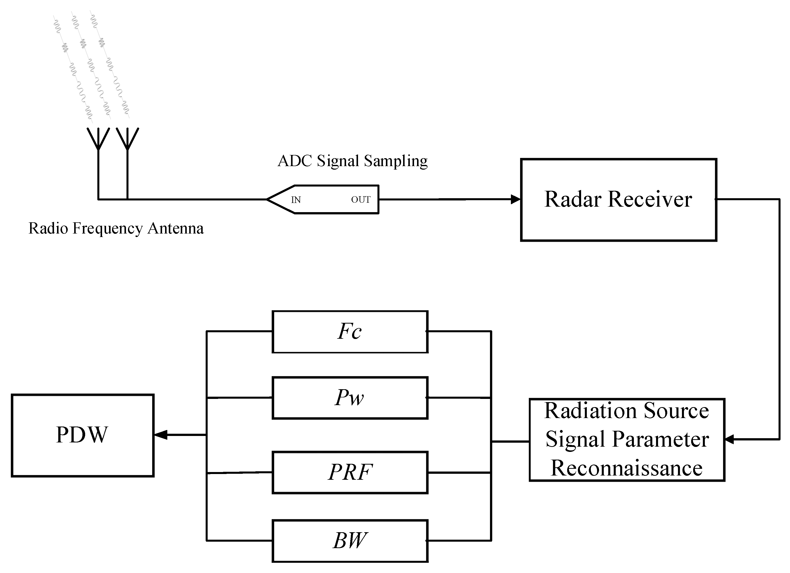
Figure 1 shows a schematic diagram of traditional static electronic jamming. In Figure 1, the active radar performs dynamic electromagnetic sensing of the external environment by transmitting signals with a specific modulation mode.
The electronic jammer intercepts the effective reconnaissance signal emitted by the radiation source to achieve rapid parameter estimation of the effective signal, then makes a specific electronic jamming decision for the radar source.
The signal S ( t ) received by the radar can be expressed as
S ( t ) = A · exp [ j · 2 π · ( f 0 t + 1 2 μ t 2 ) ]
where A is the amplitude of the signal, f 0 is the carrier frequency, μ is the frequency modulation slope of the signal, and t is the sampling time.
If the distance between the radar and the target is R , the receiver receives the radar echo signal after a delay of 2 R c . Therefore, the echo signal S r e c ( t ) received by the radar receiver can be expressed as
S r e c ( t ) = S ( t 2 R c ) + n ( t )
where R is the distance between the radar and the target, c is 3 e 8 m / s , and n ( t ) is modeled by white Gaussian noise with a distribution obeying the following formula:
n ( t ) ~ N ( 0 , σ 2 )
The receiver detects the effective linear frequency modulation (LFM) signal according to the energy accumulation method. The effective signal detection process is shown in Figure 2.
In the time-domain signal flow, the energy of the noise is much smaller than that of the effective signal. After the ADC sampling, the energy accumulation value of the 16-point discrete time-domain echo signal received by the jammer is compared with the threshold value. Here, we set the threshold amplitude to four times the amplitude energy of the echo signal. To ensure the detection of effective signals while reducing the probability of false alarms caused by noise, we adopt a 16-point energy accumulation method to detect LFM signals. When the cumulative value is continuously greater than the threshold, it represents the starting point of the effective signal, i.e., the time of arrival (TOA). Sliding detection is continuously carried out on the time-domain signal flow. When the cumulative value is continuously lower than the threshold value, it represents the time of end (TOE) of the effective signal. The time interval from the start point TOA to the end point TOE is the pulse width, P w . The time interval between the first TOA and the second TOA is the pulse repetition period, P R I . The pulse repetition rate P R F is the reciprocal of the pulse repetition period P R I [13,14,15], i.e., P R F = 1 P R I .
The carrier frequency F c of the LFM signal can be obtained by multiplying the signal delay conjugate S rec ( T 1 t ) by the original signal S rec ( t ) , where T 1 is the time delay. The effective bandwidth B W of a pulse signal can be calculated using the pulse width P w and pulse signal modulation slope μ , that is, B W = μ · P w . At this point, the pulse descriptor word (PDW) parameter estimation process for the target radar’s signal is completed.
The electronic reconnaissance process is shown in Figure 3, including the estimated parameters.
RGPO jamming adds a time delay to the received signal S ( t ) , resulting in a difference in distance between the jamming signal S j ( t ) and the real echo signal S r e c ( t ) that interferes with the target’s recognition of the real echo signal. The jamming range gate can be either positive or negative. A positive distance means that the jamming signal is far from the radar receiver, while a negative distance means that the interference signal is close to the radar receiver.
Here, we apply a jamming range gate at a distance R j to the radar signal. Therefore, the electronic jamming signal after range gate pull-off (RGPO) jamming is as follows:
S j ( t ) = S [ t 2 ( R + R j ) c ] + n ( t )
where R j is the range gate. The jamming range gate can be either positive or negative.

2.2. Balancing Parameters of the Multi-Agent Situation Information

Assuming the electronic jamming system contains N electronic jammer nodes, the situational information of a single electronic jammer agent can be expressed as follows:
X i = C i ( { Information   of   Agent   i } i N ) = C i : ( F c , P w , P R F , B W )
where F c is the center carrier frequency, P w is the signal pulse width, P R F is the pulse repetition rate, and B W is the effective bandwidth of the signal. Moreover, C i : ( F c , P w , P R F , B W ) represents the situation information of the parameter set ( F c , P w , P R F , B W ) at the ith electronic jammer agent.
Then, the situation information that the multi-agent system can perceive is expressed as
C = i = 1 N ( X i | i N i )
where i = 1 N is the sum situation information of N jammers.
Here, we assume that the weight of the parameter is γ . The parameter weight is represented as follows:
{ 4 · γ = 1 α F c = α P w = α P R F = α B W = γ
where { α F c , α P w , α P R F , α B W } corresponds to the weight of F c , P w , P R F , B W .
Because the situation parameter information between different jammer agents is not exactly the same at the same time, it is necessary to observe and balance the parameters between the different agents. A partial derivation of the reconnaissance situation parameters in the adjacent electronic jammer is carried out; the expression is as follows:
( X i X i 1 ) F c = ( C i : P a ( F c , P w , P R F , B W ) ) F c ( C i 1 : P a ( F c , P w , P R F , B W ) ) F c = ( C i | F c C i 1 | F c ) F c
where F F c is the derivative of F c with respect to the function F.
The expression of the situational information transmission of the jamming parameters ( F c , P w , P R F , B W ) between different jammer agents can be expressed as
{ ( X i X i 1 ) P w = ( C i | P w C i 1 | P w ) P w ( X i X i 1 ) P R F = ( C i | P R F C i 1 | P R F ) P R F ( X i X i 1 ) B W = ( C i | B W C i 1 | B W ) B W
where F ( P w , P R F , B W ) is the derivative of ( P w , P R F , B W ) with respect to the function F.
The purpose of having multiple sensing nodes in the electronic jamming system is to improve the accuracy of the system regarding the situation parameter information of the radiation source and to reduce the misjudgment of the situation information caused by environmental factors. If the reconnaissance parameter information of different agents is unbalanced, the parameters of each agent need to be adjusted accordingly. For example, if a node does not work or is interfered with, resulting in a large difference in the derivative of the parameter set ( F c , P w , P R F , B W ) between adjacent agents, then the problematic situation information should be ignored or discarded.
Therefore, the effective inter-agent situation parameter information C i | ( F c , P w , P R F , B W ) should be the situation information after the problematic parameters are removed. The modified situation information expression is as follows:
{ C i | F c = M e a n ( Π k N i ( C k | F c ) ) C i | P w = M e a n ( Π k N i ( C k | P w ) ) C i | P R F = M e a n ( Π k N i ( C k | P R F ) ) C i | B W = M e a n ( Π k N i ( C k | B W ) )
where the function Π k N i ( Ξ ) represents the average value of parameter set Ξ in a certain range M e a n ( Ξ ) · ( 1 ) , M e a n ( Ξ ) · ( 1 + ) . Here, is 0.1 .
Then, the multi-agent situation parameters after information sharing can be expressed as
X i N i = C B a l a n c e : ( F c , P w , P R F , B W )
where C B a l a n c e represents the balanced agent situation information and F c , P w , P R F , B W represent the balanced jamming parameters’ values.
Based on the mechanism of multi-agent parameter information sharing, dynamic situation information perception of the external electromagnetic environment is efficiently achieved.

2.3. Autonomous Decision of Jammer Agent Parameters

Through information sharing mechanisms, multi-agent jammers realize the collaborative perception of electromagnetic situation information in the whole region through cooperative means. At the same time, in order to make the jamming signal of the electronic jammer adapt to the new situation, it is necessary to control the jamming parameters dynamically and independently in real time.
Suppose that the parameter of electronic jamming agent i at time t is
P a r i t jam = K i t : { γ · ( μ F c , μ P w , μ P R F , μ B W ) }
where K i t represents the total situation of the jamming parameters of agent i at moment t , ( μ F c , μ P w , μ P R F , μ B W ) represents the corresponding parameter values of ( F c , P w , P R F , B W ) , and γ indicates the weight of each jamming parameter.
It is important to measure the rate of change between the current jamming parameters and the radar radiation source parameters. Understanding the current parameter variation trend is a key index for the subsequent jamming parameter set ( F c , P w , P R F , B W ) decision at time t + 1 . The transformation rate of the parameter set ( F c , P w , P R F , B W ) at a time between t and t + 1 can be obtained by taking the partial derivative of parameter set ( F c , P w , P R F , B W ) of the function ( P a r i t jam X i t + 1 ) . Therefore, the transformation rate t , t + 1 ( F c , P w , P R F , B W ) can be expressed as
{ t , t + 1 F c = ( P a r i t jam X i t + 1 ) F c , t , t + 1 P w = ( P a r i t jam X i t + 1 ) P w , t , t + 1 P R F = ( P a r i t jam X i t + 1 ) P R F , t , t + 1 B W = ( P a r i t jam X i t + 1 ) B W .
where ( P a r i t jam X i t + 1 ) ( F c , P w , P R F , B W ) is the derivative of ( F c , P w , P R F , B W ) with respect to the function ( P a r i t jam X i t + 1 ) .
The trend of the situation parameters for the next moment is updated for the same agent at different times. Using the situational information sharing method, the next changing process of jamming parameter K i t + 1 | ( F c , P w , P R F , B W ) is as follows:
{ K i t + 1 | F c = μ F c + ε · t , t + 1 F c , K i t + 1 | P w = μ P w + ε · t , t + 1 P w , K i t + 1 | P R F = μ P R F + ε · t , t + 1 P R F , K i t + 1 | B W = μ B W + ε · t , t + 1 B W .
where ( μ F c , μ P w , μ P R F , μ B W ) represents the corresponding parameter values of ( F c , P w , P R F , B W ) and ε is a constant with a value of 0.1.
The information about the electronic jamming parameters P a r i t + 1 jam updated at moment t + 1 can be expressed as follows:
P a r i t + 1 jam = K i t + 1 ( { Jamming   Paraments     of   Agent   i } i N i ) = K i t + 1 : ( μ F c , μ P w , μ P R F , μ B W ) .
where ( μ F c , μ P w , μ P R F , μ B W ) represents the weight of ( F c , P w , P R F , B W ) at moment t + 1 for the ith electronic jammer agent.

3. Evaluation of Jamming Effectiveness

3.1. Jamming-to-Signal Ratio Definition

To effectively jam a radar signal, it is necessary to create a jamming signal at the target receiver for the radar signal. The jamming-to-signal ratio (JSR) is a good indicator for quantifying the jamming effect. The JSR is similar to the signal-to-noise ratio (SNR), where J represents the received jamming signal energy and S represents the received radar signal energy.
Consider a self-defense electronic jamming situation in which each target has a cognitive jammer. In the case of a radar and a jammer, the jammer focuses on optimizing the jamming efficacy by learning the radar’s strategy in order to protect the target from detection [16]. To make the study easier, we consider the target to be a point target with a radar cross-section (RCS) of ρ . We assume that the radar is jammed during each beam dwell time, which is referred to as a jamming round in this article. The number of radar pulses transmitted during a jamming round is determined by the beam dwell duration and the pulse repetition interval (PRI). For the n th radar pulse in a jamming round, the carrier frequency F c is F c r ( n ) , the bandwidth B W is B w r ( n ) , the P R I is p r i r ( n ) which represents the time between the rising edge of the ( n 1 ) th and n th radar pulses, the pulse width P W is P w r ( n ) , and the transmission power is P r ( n ) . The jammer tries to align the jamming signal with the radar signal in both the time and frequency domains at each pulse. For the nth jammer pulse, the Fc is f j a m ( n ) , the BW is B w r ( n ) , the pulse delay time is d t j a m ( n ) , which indicates the time between receiving the ( n 1 ) th radar pulse and sending the next jamming pulse, the P W is P w j a m ( n ) , and the transmission power is P r ( n ) . Furthermore, the distance between the radar and the target is R and the wavelength of the radar signal is λ . The radar and jammer antenna gains are G r and G j a m , respectively. The radar and jamming signal propagation losses are L r and L j a m , respectively. The polarization matching loss coefficient between the jammer signal and the radar signal is ψ . The power of the echo at the radar receiver can be expressed as
P r s ( n ) = P r ( n ) G r 2 ρ λ 2 ( 4 π ) 3 D 4 L r
The power of the nth jamming pulse at the radar receiver is
P r j ( n ) = P j a m ( n ) G j a m G r λ 2 ψ ( 4 π ) 2 D 2 L j a m
Using an effective jamming coefficient to modify the JSR calculation formula, the average JSR for the nth radar pulse is computed as follows:
J S R ( n ) = P r j ( n ) · X f ( n ) · X t ( n ) P r s ( n ) = P j ( n ) G j a m μ 4 π D 2 L r X f ( n ) X t ( n ) P r ( n ) G r ρ L j a m
where X f ( n ) and X t ( n ) are the effective jamming factors in the frequency and time domains, expressed as
X f ( n ) = Δ f ( n ) B j ( n ) · sgn ( Δ f ( n ) ) X t ( n ) = Δ t ( n ) P w j ( n ) · sgn ( Δ t ( n ) )
where Δ f ( n ) and Δ t ( n ) are the overlapping rates in the frequency domain and the time domain, provided as follows:
Δ f ( n ) = min ( F c j ( n ) + B w j ( n ) / 2 , F c r ( n ) + B w r ( n ) / 2 ) max ( F c j ( n ) B w j ( n ) / 2 , F c r ( n ) B w r ( n ) / 2 ) Δ t ( n ) = min ( d t j ( n ) + P w j ( n ) , P R I r ( n ) + P w r ( n ) ) max ( d t j ( n ) , P R I r ( n ) )
where sgn ( x ) can be written as
sgn ( x ) = { 1 , x > 0 1 ,   otherwise

3.2. Q-Learning Method for Jamming Policy

The jamming process can be represented as a quaternion { S , A , P , } through a finite Markov decision process (MDP) [17,18]. Here, S is a finite collection of radar states, with state s S determined by the radar pulse parameters ( F c , P w , P R F , B W ) , and A is a finite set of jammer actions, where action a A is defined by the jamming pulse parameters. When the jammer performs action a ( n ) , the transition probability P ( s ( n + 1 ) s ( n ) , a ( n ) ) describes how the present state s ( n ) transitions to the next state s ( n + 1 ) . In addition, is the reward after each action is taken.
Reinforcement learning is an effective method for solving MDP problems, with the key being the determination of the optimal policy π : S A to determine which action should be performed in each state. The state-value function for policy π is proposed to evaluate the effect of a policy, as follows:
v π ( s ) = E π [ m = 0 ξ m m s m = s ]
where E π [ · ] stands for the expected value with the given policy π and ξ [ 0 , 1 ) is the discount rate of the reward R , which means that a long-term reward is considered and its influence decreases with time.
The update strategy of the electronic jammer parameters based on Q-learning [19,20,21,22] is as follows:
Q * ( s , a ) = Q ( s , a ) + η · ( r ( s , a ) + ξ · max a Q ( s , a ) Q ( s , a ) )
where s is the current jamming parameter status of the electronic jammer, a is the current action taken, r ( s , a ) indicates the reward after the operation of action a , max a Q ( s , a ) is the best parameter adjustment action taken by the jammer agent at the next moment, η is the learning rate parameter, and ξ is the discount factor parameter. In continuous tasks, the discount factor ξ is usually set in the range [0,1) in order to ensure that the reward r ( s , a ) does not diverge to infinity.
In our work, the jammer applies jamming to the radar by changing the signal characteristic parameters. The more realistic the electronic jamming signal is compared to the real echo signal, the better the interference effect. Here, a represents the action space of each of the jamming parameters ( F c , P w , P R F , B W ) and s represents the current state of each jamming parameters. At the beginning of moment t , when we perform action a on the jamming parameter ( F c , P w , P R F , B W ) the jammer obtains the current local state information as s and the current Q table as Q ( s , a ) . At the same time, it receives a reward r ( s , a ) for executing action a . Obviously, the reward function is mainly used to reward expected behaviors and punish undesirable actions. Then, we use the r ( s , a ) + ξ · max a Q ( s , a ) corresponding to action a as the estimated value. Finally, Q * ( s , a ) is updated using Formula (23). The above operation is repeated until the jamming parameters ( F c , P w , P R F , B W ) reach the optimal state.
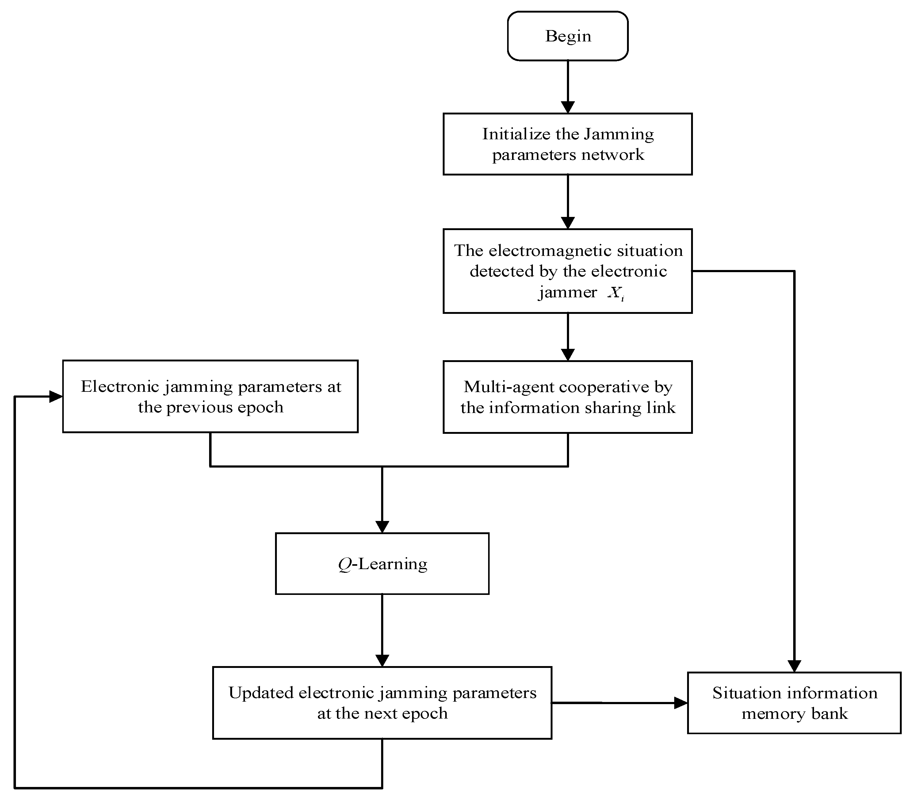
The dynamic cognitive electronic jamming strategy based on Q-learning can realize real-time perception based on the environmental electromagnetic situation and update the electronic jamming parameters of the system in real time according to the perception results, ensuring that the jamming strategy of the electronic jamming system always has the best possible status. The system flow is shown in Figure 4.
In Figure 4, the distributed electronic jammer can obtain spatial electromagnetic situation information among multiple agents through collaborative perception. The agent situation after information sharing is expressed as X . The reconnaissance situation information at the current moment and the previous moment is input into the intelligent decision system. The optimal jamming strategy for the next epoch implemented by the electronic jamming machine is realized through the Q-learning decision algorithm.

4. Experiment and Analysis

A distributed multi-agent cooperative electronic jamming system uses a process of continuous correction during the process of interaction with the external electromagnetic environment, in which the jamming parameters change dynamically. In the process of electronic confrontation, electronic jammer agents constantly learn from and evolve with the electromagnetic environment to achieve the optimal jamming effect.
In order to verify the effectiveness of this method, the following experiments were designed.
Table 1 shows the change trend of the electromagnetic situation information of the radiation sources in different stages. The period from T0 to T5 indicates the changes in the radiation source parameters at every 10-min interval. It can be seen from the table that the signal parameters emitted by the electromagnetic radiation source are changed in different stages, which can effectively avoid the problem of tracking brought about by the single parameters of the radiation source emission signal. The radiation source characteristics with parameter variations have a certain anti-jamming function. Electronic jammers need to perceive the change trend of the radiation source situation information quickly in a dynamic and complex electromagnetic environment. Moreover, the information is used as prior information to realize autonomous perception and a dynamic cognitive jamming strategy.

4.1. Situation Information Sharing

Based on the parameter situation information of the radiation source emission signal in Table 1, the electronic jammer is able to realize the electromagnetic parameter estimation and modulation type recognition of the radiation source through the passive electronic reconnaissance system.
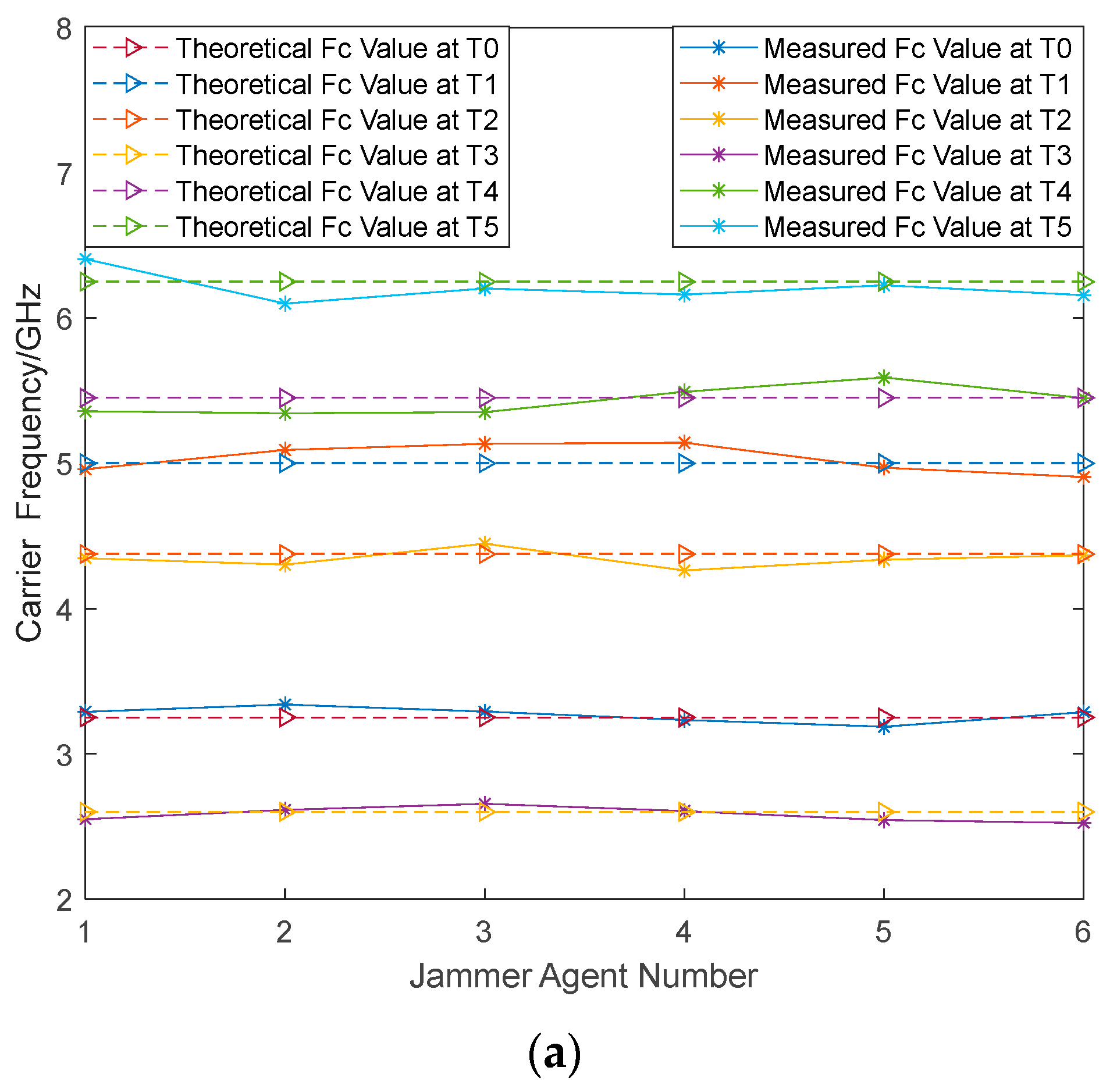
In this experiment, six electronic jammer agents were distributed isometrically around the radiation source to realize the dynamic perception of the spatial global electromagnetic situation information. The signal-to-noise ratio of the environment was set to 0 dB, and the noise was assumed to be white Gaussian noise with a power density of one half. Because the situation parameter information between each agent is not completely consistent, it is necessary to balance the situation parameters obtained by the distributed electronic agents. The balanced jammer agent parameters can be expressed as X i N i = C Balance : P a ( F c , P w , P R F , B W ) . The results are shown in Figure 5.
The different characteristic parameters (including F c , P w , P R F , B W ) of the radiation source perceived by the six electronic jammers at different sampling times are shown in Figure 5. In this experiment, the signal-to-noise ratio was 0db. Among them, the transverse coordinate is the agent number, the longitudinal coordinate is the value of the corresponding characteristic parameters, the virtual line represents the theoretical parameter value, and the real line represents the actual measurement value after the balanced treatment.
The radiation source signal parameter estimation results based on information sharing are shown in Table 2.
The relationships between P R I and P R F can be written as
P R I = 1 P R F
The relationships between μ , P w , and B w are as follows:
μ = B w P w
The multi-agent situation information sharing method can fully characterize the current electromagnetic situation. At the same time, the situation parameter imbalance caused by insufficient single jammer agent perception ability can be avoided.

4.2. Optimization of the Jamming Parameters in Real Time

The characteristic parameters X i of the balanced radiation source signal are input into the electronic jammer intelligence system as environmental perception information, and the real-time intelligent jamming strategy for the radiation source target is realized using the Q-learning method.
Hyperparameters are elements that must be set in Q-learning in order to adjust learning strategies. In this experiment, the learning rate η was set to 0.01 and the discount factor ξ was set to 0.9. The Q table of all electronic agents was initialized to 0 and the state s of each agent was randomly initialized.
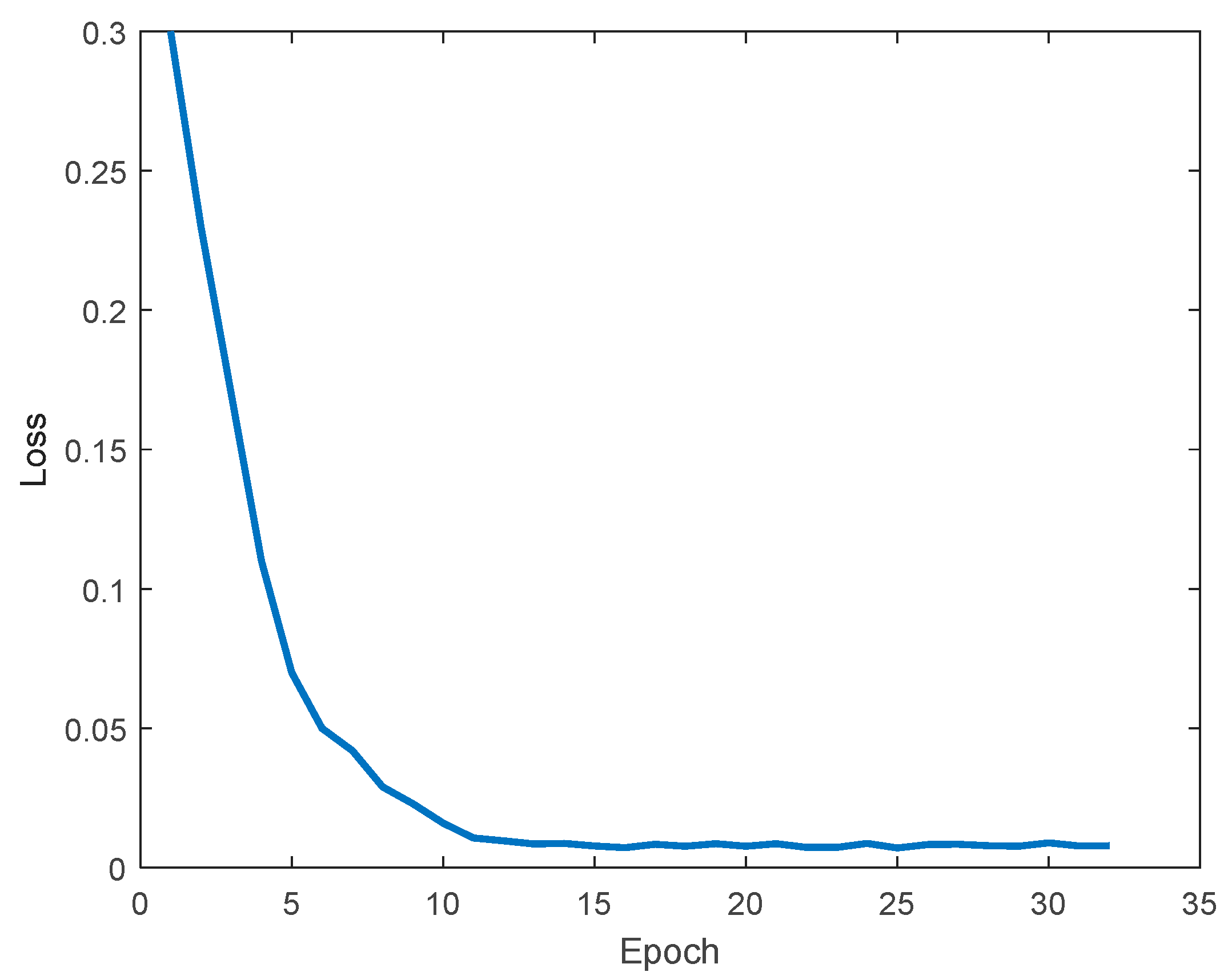
Based on the shared electromagnetic situation information obtained in Section 4.1, the jamming parameters of the electronic jammers can change independently with the change in the radiation source parameters and achieve accurate and effective jamming of the radiation source. The reward function and the loss function based on the Q-learning method in a certain time period are shown in Figure 6 and Figure 7.
Figure 6 and Figure 7 show the reward–return function curve and loss function curve for one period. They demonstrate that the electronic jamming parameters achieve convergence in a very short period of ten epochs. Moreover, the loss value reaches 0.0016 and the reward value reaches up to 0.9924, thereby realizing the rapid updating of the electronic jamming parameters.
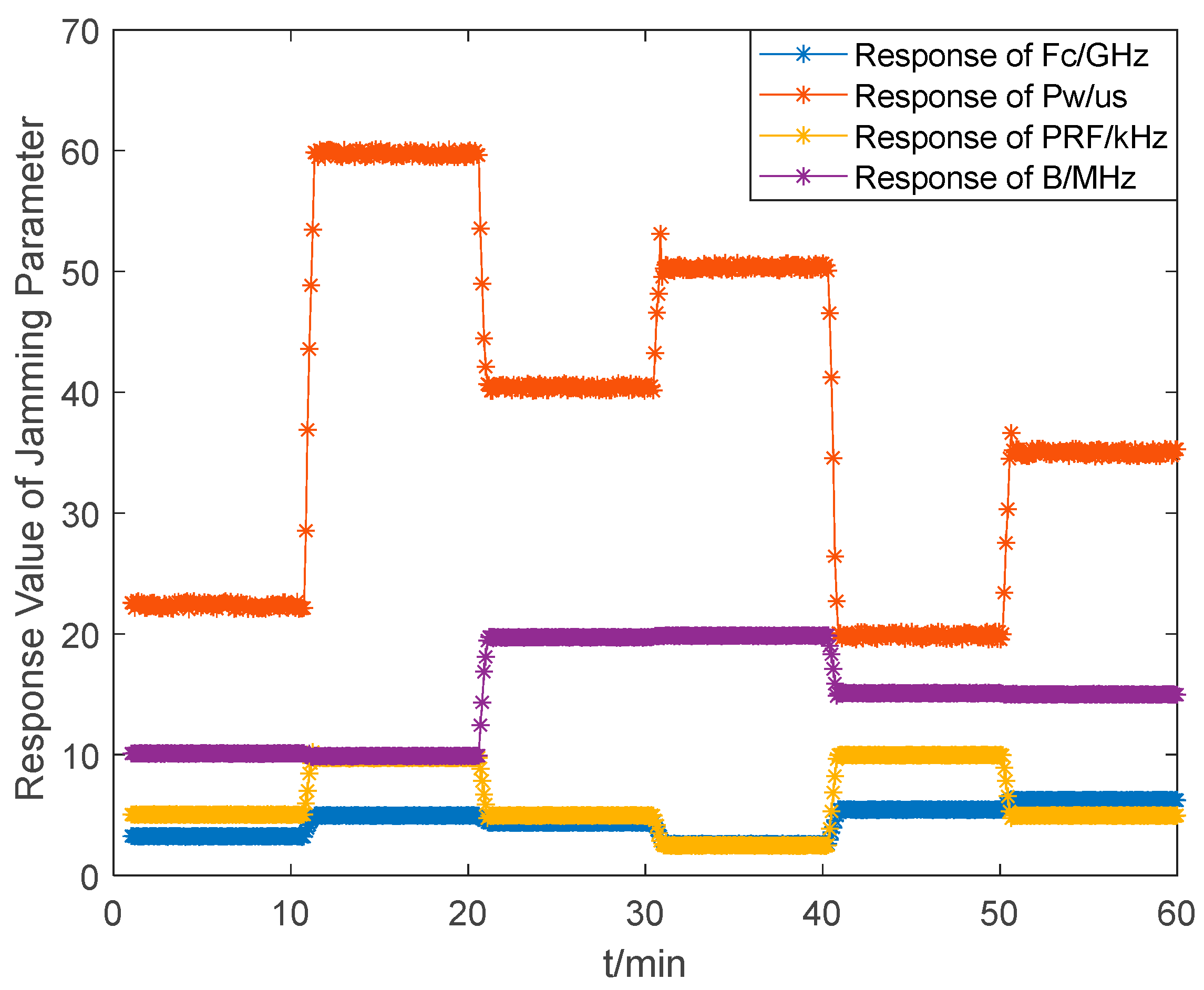
Figure 8 shows a real-time jamming parameter response based on Q-learning with the radiation source situation parameters in Table 1 changed.
As can be seen in Figure 8, the electronic jammers can quickly estimate the current electromagnetic situation and adjust the jamming parameters in the next epoch to adapt to the current electromagnetic environment when the radiation source changes.

4.3. Effect of the Number of Jammers on Perception Accuracy

Considering the influence of environmental factors, we set the reconnaissance error probability of the jamming parameters to 5%. The ability of different numbers of electronic jammers to perceive the electromagnetic situation information was analyzed after 1000 independent Monte Carlo experiments.
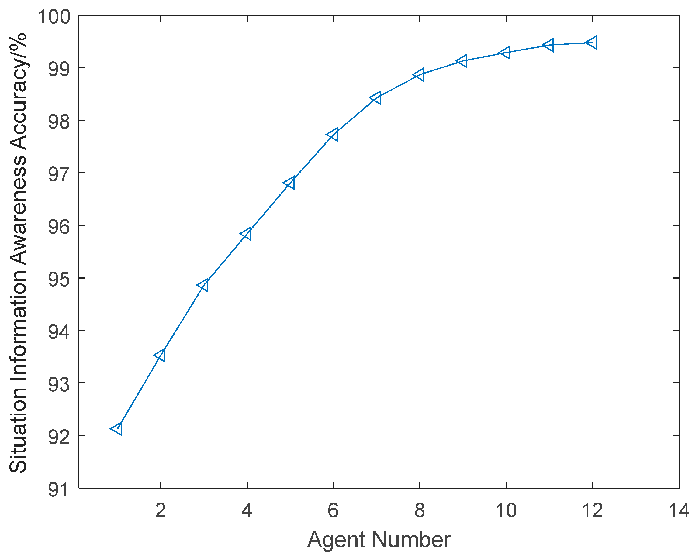
The accuracy result for different jammers is shown in Figure 9.
In Figure 9, the accuracy increases as the number of electronic jamming agents grows. The accuracy of the situational information P ( X ) perceived by the distributed jamming agents can be expressed as follows:
P ( X ) = l = 1 N P ( X l | F c ) + P ( X l | P w ) + P ( X l | P R F ) + P ( X l | B W ) 4
where P ( X l | ( F c , P w , P R F , B W ) ) represents the accuracy of the parameters ( F c , P w , P R F , B W ) in terms of the situation information X l .
The estimation error ( P a r i ) of the parameter set ( F c , P w , P R F , B W ) can be expressed as follows:
( P a r i ) = n = 1 1000 P a r i _ real P a r i _ estimate 2 1000 P a r i _ real × 100 %
where P a r i _ real is the theoretical value and P a r i _ estimate is the actual measurement value of the parameter set ( F c , P w , P R F , B W ) .
Compared with the perception of radiation source information by a single agent, multiple agents are able to obtain a more accurate situational awareness of the radiation sources. When the number of electronic jamming agents reaches seven, the recognition rate can reach 98.43%.

4.4. Analysis of Jamming Effectiveness Evaluation

In order to verify the effectiveness of our proposed jamming method, range gate pull-off (RGPO) jamming was carried out on the target. The distance between the radar and the target was 100 km, and the range gate for the jamming target was 10 km. Other parameters in our simulation were as follows: G r = 20 dB, G j a m = 5 dB, L r = 10 dB, L j a m = 7 dB, ρ = 1 m2. Considering that radar antennas are typically linearly polarized, whereas jammer antennas are circularly or tangentially polarized, γ was set to 0.25, κ was set to 0.8, and ε was set to 0.1. The other radar parameters were set as shown in Table 1 in different stages. In particular, six electronic jamming agents were distributed in the system.
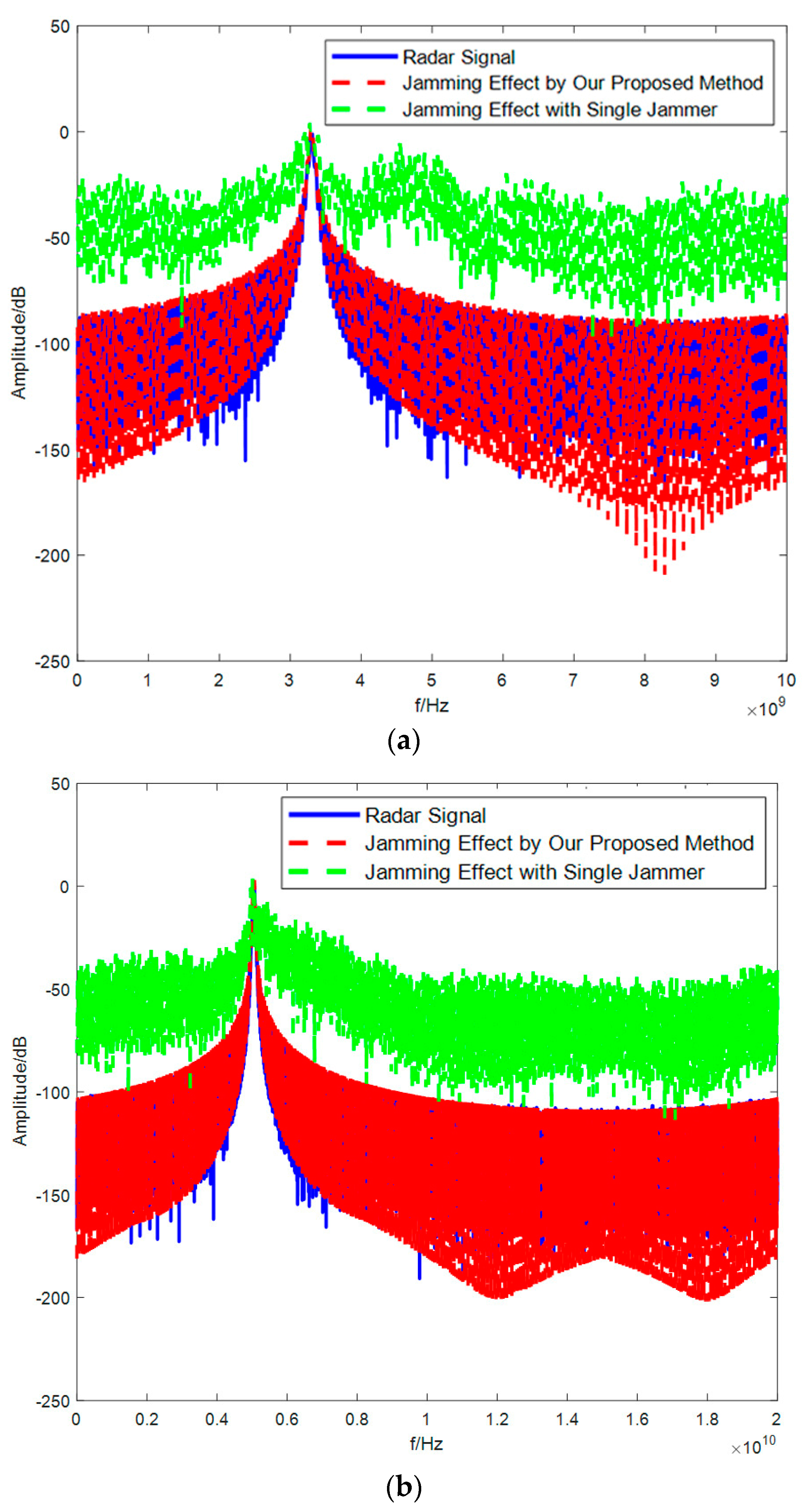
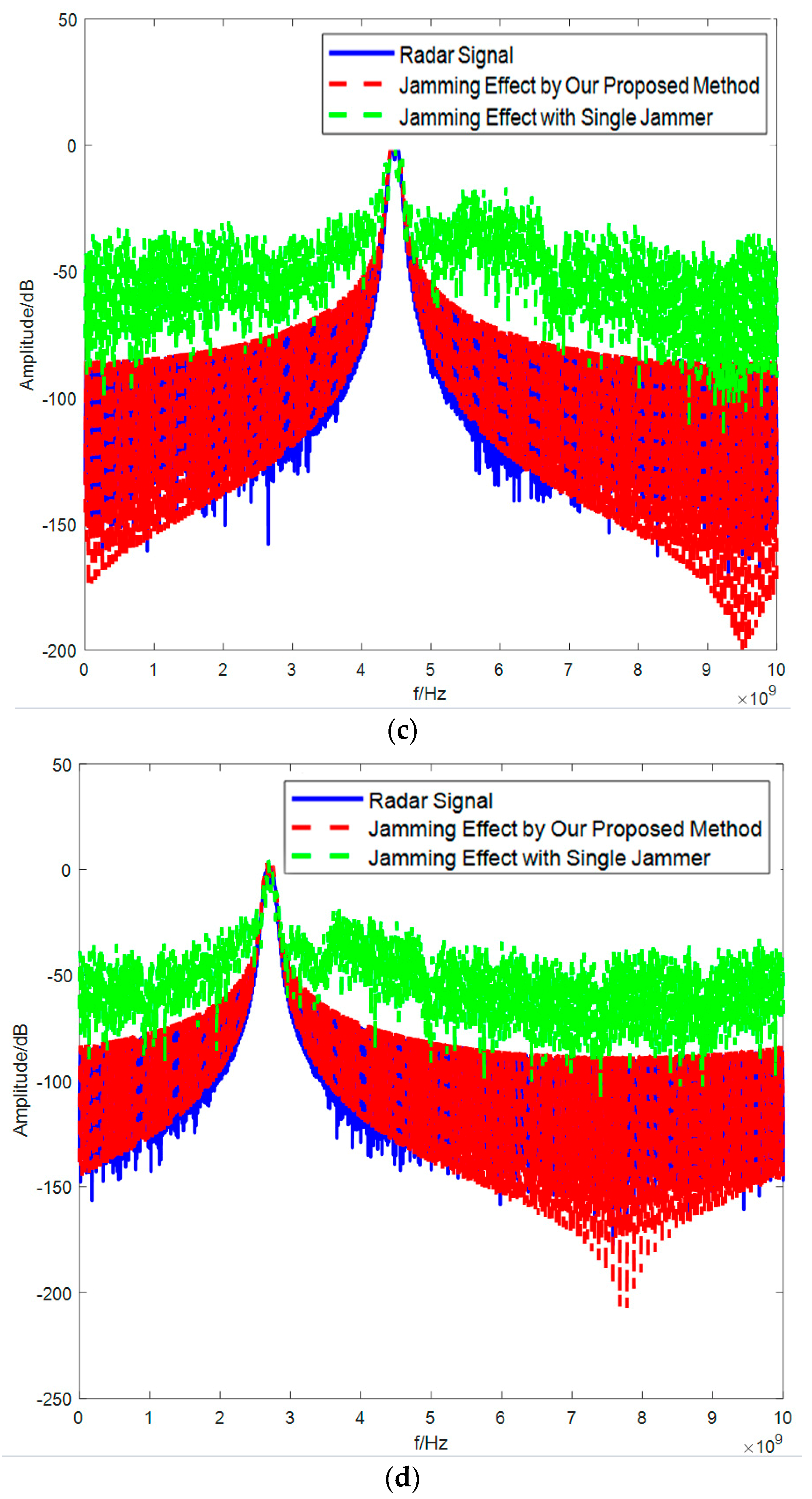
We compared the performance of our algorithm with six jammers based on a distributed information sharing method and jamming with a single jammer. Figure 10 shows the jamming effect of the two methods from T0 to T5.
In Figure 10, compared to the jamming method with a single jammer, the jamming signal spectrum of our proposed method is closer to the real radar signal. Additionally, the sidelobe power of the jamming signal taken by our proposed method is lower than that taken by the method with a single jammer, which reduces the threat of the jamming signal, thereby improving the survivability of the jammers.
According to the definition of the JSR in Section 3.1, we calculated the JSR value of the jamming signal of the two methods in different stages.
In Table 3, it can be seen that the JSR value of the jamming signal generated by our method is smaller than that generated by the jamming method with a single jammer in each stage. This result further validates the effectiveness of our method. Table 4 shows the feasibility verification of our method for the jamming parameter set ( F c , P w , P R F , B W ) .

5. Conclusions

In this article, we have proposed a new electronic jamming method based on a distributed information sharing mechanism. This method, which is based on Q-learning, can realize the real-time perception of the external electromagnetic environment and the autonomous updating of the jamming parameters. At the same time, it can realize a fast and accurate response from the jamming system and improve the concealment of jamming signals. Compared with the jamming method with a single jammer, the proposed distributed multi-agent electronic jamming method based on information sharing can achieve effective jamming with a lower JSR. Therefore, the concealment of the jammer system is improved, and the survival probability of the jammer is enhanced. Moreover, the proposed method provides practical advantages for intelligent electronic jamming systems and can serves as inspiration for future cognitive electronic jammers.

Author Contributions

Conceptualization, Z.J. and P.Z.; methodology, P.Z.; software simulation, P.Z. and Y.H.; data processing and analysis, P.Z. and Y.H.; conclusion analysis, Y.H.; writing-original draft preparation, P.Z.; writing-review and editing, Z.J.; funding acquisition, Y.H. All authors have read and agreed to the published version of the manuscript.

Funding

This research was funded by the NSFC under Grant No. U19A2054 and the China National Funds for Distinguished Young Scientists under Grant No. 61525403. This research was also supported by the Zhejiang International Youth Talent Fund of Zhejiang Lab.

Data Availability Statement

The data presented in this study are available on request from the corresponding author.

Conflicts of Interest

The authors declare no conflict of interest.

References

  1. Cywiński, A.; Ostrowski, R.; Strzelec, M. Electronic warfare in the optical band: Main features, examples and selected measurement data. Def. Technol. 2020, 17, 1636–1649. [Google Scholar] [CrossRef]
  2. Smith, C.R.; Grasso, R.; Pledger, J.; Murarka, N. Trends in electro-optical electronic warfare. Proc. SPIE 2012, 8543, 854392. [Google Scholar] [CrossRef]
  3. Zhou, Y.; Rao, B.; Wang, W. UAV swarm intelligence: Recent advances and future trends. IEEE Access 2020, 8, 183856–183878. [Google Scholar] [CrossRef]
  4. Zhou, L.; Leng, S.; Liu, Q.; Wang, Q. Intelligent UAV swarm cooperation for multiple targets tracking. IEEE Internet Things J. 2021, 9, 743–754. [Google Scholar] [CrossRef]
  5. Wang, X.; Huang, T.; Liu, Y. Resource allocation for random selection of distributed jammer towards multistatic radar system. IEEE Access 2021, 9, 29048–29055. [Google Scholar] [CrossRef]
  6. Zhou, Z.; Rao, B.; Xie, X. The influence mechanism of UAV group on the detection performance of air defense radar. In Proceedings of the 2018 3rd International Conference on Automation, Mechanical Control and Computational Engineering (AMCCE 2018), Dalian, China, 12–13 May 2018; Atlantis Press: Beijing, China, 2018; pp. 338–343. [Google Scholar]
  7. DARPA. Behavior Learning for Adaptive Electronic Warfare. Available online: https://www.fbo.gov (accessed on 6 October 2010).
  8. Kingsley, N.; Guerci, J.R. Adaptive amplifier module technique to support cognitive RF architectures. In Proceedings of the IEEE Radar Conference, Cincinnati, OH, USA, 19–23 May 2014; pp. 1329–1332. [Google Scholar]
  9. Fu, J.; Wan, Y.; Wen, G.; Huang, T. Distributed robust global containment control of second-order multiagent systems with input saturation. IEEE Trans. Control. Netw. Syst. 2019, 6, 1426–1437. [Google Scholar] [CrossRef]
  10. Yan, Y.; Huang, J. Cooperative output regulation of discretetime linear time-delay multi-agent systems. IET Control. Theory Appl. 2016, 10, 2019–2026. [Google Scholar] [CrossRef]
  11. Wang, S.; Bao, Y.; Li, Y. The architecture and technology of cognitive electronic warfare. Sci. Sin. Inf. 2018, 48, 1603–1613. [Google Scholar] [CrossRef]
  12. Xing, Q.; Zhu, W.G.; Jia, X. Intelligent radar countermeasure based on Q-learning. Syst. Eng. Electron. 2018, 40, 1031–1035. [Google Scholar]
  13. He, J.-H. FPGA Software Design for Reconnaissance and Jamming Integration Processor; Harbin Engineering University: Harbin, China, 2017. [Google Scholar]
  14. Zuo, S.; Song, Y.; Lewis, F.L.; Davoudi, A. Output containment control of linear heterogeneous multi-agent systems using internal model principle. IEEE Trans. Cybern. 2017, 47, 2099–2109. [Google Scholar] [CrossRef] [PubMed]
  15. Li, Z.; Ren, W.; Liu, X.; Fu, M. Distributed containment control of multi-agent systems with general linear dynamics in the presence of multiple leaders. Int. J. Robust Nonlinear Control. 2013, 23, 534–547. [Google Scholar] [CrossRef]
  16. Osner, N.R.; du Plessis, W.P. Threat evaluation and jamming allocation. IET Radar Sonar Navig. 2017, 11, 459–465. [Google Scholar] [CrossRef]
  17. Rabiner, L.R. A tutorial on hidden markov models and selected applications in speech recognition. Proc. IEEE 1989, 77, 257–286. [Google Scholar] [CrossRef]
  18. Han, L.; Ning, Q.; Chen, B.; Lei, Y.; Zhou, X. Ground threat evaluation and jamming allocation model with markov chain for aircraft. IET Radar Sonar Navig. 2020, 14, 1039–1045. [Google Scholar] [CrossRef]
  19. Feng, H.Z.; Liu, H.W.; Yan, J.K.; Dai, F.Z.; Fang, M. A fast efficient power allocation algorithm for target localization in cognitive distributed multiple radar systems. Signal Process. 2016, 127, 100–116. [Google Scholar] [CrossRef]
  20. Bui, V.H.; Nguyen, T.T.; Kim, H.M. Distributed operation of wind farm for maximizing output power: A multi-agent deep reinforcement learning approach. Access IEEE 2020, 8, 173136–173146. [Google Scholar] [CrossRef]
  21. Zhang, Y.; Peng, L.; Xu, R.; Li, J. A distributed low-redundancy information sharing algorithm in ad hoc networks with directional antennas. Procedia Comput. Ence 2018, 131, 1142–1149. [Google Scholar] [CrossRef]
  22. Peng, T.; Leckie, C.; Ramamohanarao, K. Information sharing for distributed intrusion detection systems. J. Netw. Comput. Appl. 2007, 30, 877–899. [Google Scholar] [CrossRef]
Figure 1. Electronic jamming system.
Electronics 12 02130 g001
Figure 2. Pulse energy detection and pulse width measurement.
Electronics 12 02130 g002
Figure 3. The estimation process of electromagnetic parameters of radiation sources.
Electronics 12 02130 g003
Figure 4. Electronic jamming flow chart based on multi-agent information sharing and Q-learning methods.
Electronics 12 02130 g004
Figure 5. The multi-agent electronic jammer measures the electromagnetic situation information at different times. (a) The measurements and theoretical values of Fc; (b) the measurements and theoretical values of PW; (c) the measurements and theoretical values of PRF; (d) the measurements and theoretical values of BW.
Electronics 12 02130 g005aElectronics 12 02130 g005b
Figure 6. The reward–return curve within one period.
Electronics 12 02130 g006
Figure 7. The loss function curve within one period.
Electronics 12 02130 g007
Figure 8. Dynamic response curve of the jamming parameter matrix over time.
Electronics 12 02130 g008
Figure 9. The accuracy of situational information awareness trends with the number of distributed jammers.
Electronics 12 02130 g009
Figure 10. The jamming effect performance of our algorithm with six jammers based on the distributed information sharing method compared to jamming with a single jammer. (a) Comparison of the jamming effects of the two methods in stage T0. (b) Comparison of the jamming effects of the two methods in stage T1. (c) Comparison of the jamming effects of the two methods in stage T2. (d) Comparison of the jamming effects of the two methods in stage T3. (e) Comparison of the jamming effects of the two methods in stage T4. (f) Comparison of the jamming effects of the two methods in stage T5.
Electronics 12 02130 g010aElectronics 12 02130 g010bElectronics 12 02130 g010c
Table 1. Electromagnetic parameter information at different times.
StageFc/GHzPw/usPRF/HzBW/MHz
T03.2522.5500010
T156010,00010
T24.37540500020
T32.650250020
T45.452010,00015
T56.2535500015
Table 2. Measured values of electromagnetic parameters at different times.
StageFc/GHzPw/usPRI/us μ /Hz/s
T03.253922.367198.34.492 × 1011
T14.975859.76102.761.634 × 1011
T24.386340.432200.8434.9317 × 1011
T32.603650.372399.3463.9705 × 1011
T45.462019.874100.2647.5475 × 1011
T56.251035.006201.1494.285 × 1011
Table 3. Jamming signal JSR value of the two methods in different stages.
MethodJSR
T0T1T2T3T4T5
Our algorithm1.02150.99871.00321.03861.01081.1250
Jamming with a single jammer1.67321.78511.57381.62101.83271.5248
Table 4. The feasibility verification of our method for the jamming parameter set ( F c , P w , P R F , B W ) .
NO.Evaluation
Indicator
Correlation with
Evaluation Result
1Fcpositive
2Pwpositive
3PRFpositive
4BWpositive
Disclaimer/Publisher’s Note: The statements, opinions and data contained in all publications are solely those of the individual author(s) and contributor(s) and not of MDPI and/or the editor(s). MDPI and/or the editor(s) disclaim responsibility for any injury to people or property resulting from any ideas, methods, instructions or products referred to in the content.