Abstract
There are many possible LED lighting applications where separate regulation of the LED current (luminous flux) of individual LED strings would be desirable—specialized variable correlated color temperature lights for ambient lighting, decorative lighting, surgical lights, horticultural lights, etc. Separate regulation of the current or light flux of individual LED strings is associated with a known problem: the necessity of using a controllable LED driver for each string, which increases the total component count, overall system complexity and costs. One of the possible solutions—a current source mode single-inductor multiple-output LED driver—was discussed in previous different papers. However, the practical implementation of this solution was not discussed in detail. This article aims to correct this omission.
1. Introduction
The idea of a segmented LED light source (SLLS) and an appropriate LED driver for the color/tone regulated LED lamp considered in the scope of this work is an adaptable light source delivering necessary illuminance to the desired area of the illuminated surface. This LED module is formed of an SLLS with independently dimmable/switchable high-power LEDs on its separate branches. Independent driving of this amount of high-power LEDs is expensive and complicated. Therefore, a special multiple-channel LED driving approach (single-inductor multiple-output (SIMO) current source mode (CSM) LED driver) has been chosen to overcome the shortcomings mentioned above. The same multiple-output driving approach can be useful in many other LED applications such as horticultural lighting, controllable RGB ambient lighting, adjustable correlated color temperature (CCT) applications, matrix automotive lighting, etc. The approach itself can be considered as a multilevel current and light regulation method with fluent control between levels. The current regulation in the given application is not the primary goal (the primary goal is light regulation) and it is not explicit. However, having an isolating and parallelizing current commutating matrix and combining it with a set of simplified uncontrolled current sources with one controlled current source, it becomes possible to achieve more straightforward and explicit current regulation that widens the range of potential applications. For instance, it enables the use of a similar approach in battery applications—battery energy storage systems and chargers for larger or smaller all-electric vehicles, for example, personal mobility vehicles like wheelchairs.
The main idea of an LED driver for the SLLS considered in the scope of this paper is derived from the SIMO CSM driver which has been described most accurately in [1]. The authors of [1] describe the SIMO CSM driver as a multiple-output converter with current delivery functions suitable for current consumers such as LEDs and as an approach to simplify independent output controls in comparison with traditional voltage-source-mode (VSM) converters. These statements are validated by experimental results of the CSM single-inductor dual-output (SIDO) converter example. They also mention the necessity of using a current generator (constant current source) stage at the input of SIMO CSM as a drawback, as the most commonly used power supplies are voltage sources.
A similar idea of current source mode regulators has also been studied by the authors of articles [2,3,4,5] several years ago, as well as by other authors quite recently in [6,7,8,9,10]. In [1], as an advantage of the SIMO CSM driver, the simultaneous voltage step-up and step-down functions for multiple-output applications are mentioned. However, the simulations in [2] show that the conditions for energy transfer exist only if the sum of the voltages across all energy transferring (output) capacitors (C21 and C2k in Figure 1) does not exceed the input voltage when using CSM buck topology as an output stage for a SIMO converter.

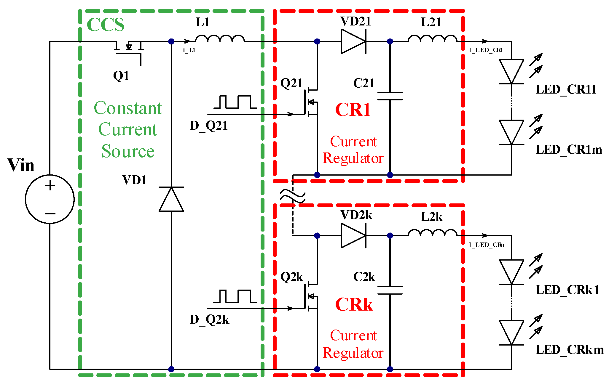
Figure 1.
SIMO CSM driver idea [2].
In [3,4], the steady-state performance of three conventional VSM converters (buck, boost and buck–boost) in conjunction with LEDs has been compared with the performance of their corresponding CSM converters by several criteria (maximal dynamic gain, nonlinearity and span of usable duty cycle); in addition, static losses were estimated for CSM converters, and it was found that CSM converters are suitable for LED driving when taking into account all this criteria.
In [5], a non-inverting buck–boost converter is considered as a combination of the constant current source (CSS) stage with the single current regulator (CR) stage, which in fact, is the initial configuration of SIMO CSM converters discussed above.
The essence of the idea stated by all these articles is that the current in each channel (individual LED or LED string) can be regulated in a simple way without the need for implementation of closed-loop regulation when using current regulators (CR). The single inductor L1 is used for constant current forming as a constant current source (CSS) for whole circuits, as shown in Figure 1. Only this part of the circuit (single-inductor-based constant current source) needs to be equipped with closed loop regulation (current feedback). The alternative method for independent current regulation is using independent LED drivers (constant current sources equipped with closed-loop regulation) for each channel, which complicates the control system and increases the number of components and the cost of a circuit.
Additionally, in [6,7], a different combinations of CSM buck and boost topology output stages in an SIDO converter are derived, analyzed and summarized by the article authors. In [8,9], the complete set of 16 possible configurations of SIMO CSM converters with multiple outputs is summarized.
In [10], an example of the practical usage of a three-output SIMO converter as an off-line converter is analyzed.
Usually, a configuration of multiple output converters with colored LEDs is considered for applications where precise color control during dimming is required and relatively low-power LEDs are used (in applications such as display backlighting) [10,11,12,13,14,15].
We are highlighting that our proposed driver configurations are the most appropriate for use with high-power and high-current LEDs in applications where absolutely precise color representation is not critical, but the most critical factor is a fluent transition between different color combinations. The applications where such a driver would be the most appropriate are white light with adjustable CCT (two colored LEDs) and horticultural lighting (two to four different color LEDs).
In contrast with the common inductorless representation of CR stages, we use inductors L21 … L2k to show the inherent current source nature of the current regulator, as shown in (Figure 1).
SIMO CSM efficiency-related issues have been considered in several articles. Efficiency improvement using the adaptive current bus approach is proposed in [16], and restriction with low-frequency pulse width modulation (PWM) dimming is described (however, this restriction could be under discussion).
Another article on SIMO CSM efficiency issues is [17], with a proposal of soft switching. However, the analysis and discussion of the efficiency results are not presented in the paper.
The question is the impact on the efficiency of the whole driver of the presence of a series diode in the circuit of each individual channel of the driver, especially the in case of using high-power LEDs with high current rates (in the rate of several amperes). The proposed improvement of this issue is discussed further in one of the sections of the paper.
Also, there is lack of discussion on driving circuit implementation for SIMO CSM drivers in existing papers. As the number of controllable switches not referenced to the ground (negative node) or positive node is equal to n − 1, where n is the number of independent driver channels, isolated gate driving circuits or other special driving approaches may be required for proper MOSFET transistor driving. Thus, particular attention in this paper has been paid to this issue.
Another topic for discussion is CCS as the input for independent channel current regulators. For the initial investigation, a prototype with an MP24833 integrated circuit (IC)-based CCS was made, which is discussed in the following section. However, the different inductor current limiting/forming control strategies can be implemented using other ICs or control methods, which is another direction for further research.
So, the purpose of this paper is the practical validation of multiple output LED drivers with the simple control method described in the papers mentioned above. The prototype of the modified SIMO LED driver discussed in further sections of this paper has been prepared for the validation of the issues listed above. A detailed discussion is given in the following sections.
2. Implementation of Constant Current Source Based on Common Existing Solution
There are many possible LED driver implementation options. However, existing LED drivers mostly are based on switch mode power converters (SMPC) with closed current regulation circuits due to several advantages. The most valuable among them is high efficiency. Buck SMPC is the most commonly used candidate for these purposes. A common simplified buck SMPC-based constant current LED driver is shown in Figure 2. An LED driver can be considered as a matching element between a voltage source and an electrical current consumer.
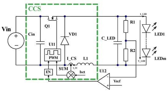
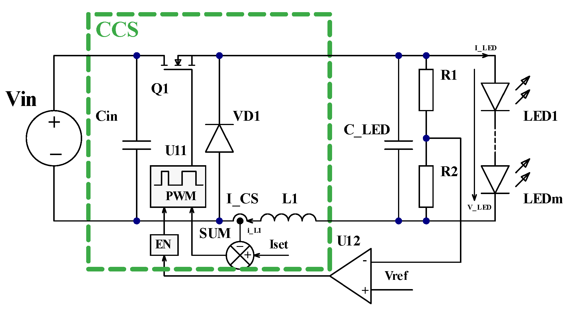
Figure 2.
One of the considered options with non-isolated driving of independent channel CRs for practical validation.
Current feedback is formed by the current sensor I_CS, which measures the actual current i_L flowing through choke L1, adder SUM, which gives an error signal (the difference between the actual i_L1 and set current I_set), and the control unit U11, which consists of a regulator and a pulse width modulator (PWM). According to the received error signal, it forms a control signal for transistor Q1. Since the current source without load theoretically can generate an infinitely high voltage on its nodes, the protection of the converter output is applied: an output voltage limiter based on comparator U12, which compares the voltage from the divider R1, R2 with the maximal set value.
Such a typical LED driver with minor modifications can serve a CSM source function. These minor modifications include the removal of the output capacitor C_LED and the output voltage limiter, which is formed by R1, R2 and U12 in Figure 2, or increasing the value of the voltage limiter to the required level, which must be equal to the voltage drop value across all series-connected LEDs in all channels with a small margin.
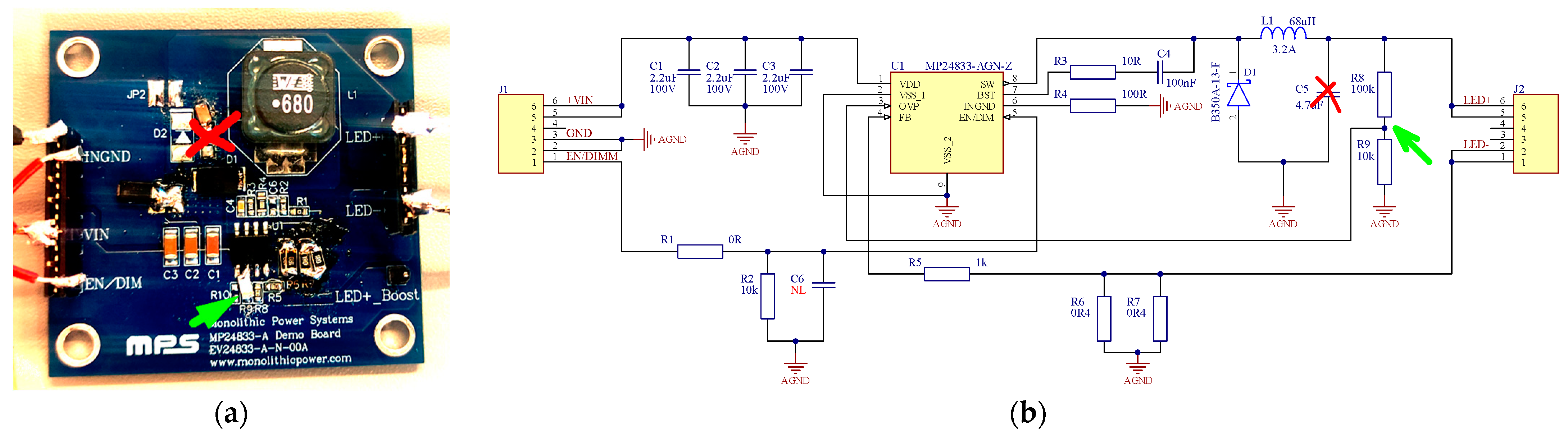
For experimental validation, a modified EV24833-A-N-00A buck/boost configurable development kit based on MPS MP24833 LED driver IC [18] was used in the scope of this work, as shown in Figure 3. On this development board, the changes mentioned above have been made, thus achieving the desired behavior of the CCS: the removal of capacitor C5 and adjustment of the voltage divider R8, R9.
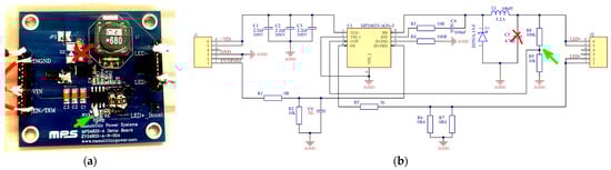
Figure 3.
EV24833-A-N-00A buck/boost configurable development board based on MPS MP24833 LED driver IC with modifications to perform in CCS mode: (a) picture with changes on the board; (b) electrical circuit schematic of evaluation kit board [18] with necessary changes; red cross—removed capacitor; green arrow—parts of voltage divider to be modified.
The approach considered in the scope of this paper (the modification of an existing LED driver to CCS and using it in combination with additional modified CRs stages) can be used for upgrading existing no-controllable LED lighting systems to adjustable light output systems with simplified control.
3. Discussion on the Efficiency of CSM SIMO LED Driver
It is evidently seen from the circuit shown in Figure 1 that the overall efficiency of the SIMO CSM driver is noticeably lower in comparison with the bare buck converter in CCS mode as an additional CR conversion stage(s) is in use with its own controllable and uncontrollable switches and their power loss. The CCS stage current always flows through CR stages. To simplify the control system of the CR stage and the whole system (which is one of the main advantages of this configuration), uncontrolled diodes VD1 … VDk are used as top switches in CR stages. When the CR stage gives 100% light/current output, the whole current flows through this uncontrolled diode, causing high power loss, especially if there is a small number of connected LEDs in the regulated string.
There are ways for efficiency improvement, which are considered in the scope of this paper. One of them is the replacement of a high-side uncontrolled diode by a controllable transistor switch, which complicates the driving circuit. Another way is using CR stages in combination with parallel controlled switches, thus bypassing CR’s diode. This approach also complicates control; however, it allows for the elimination of diode-associated power losses over part of the regulation range with higher output power and will be discussed in the following sections of this paper.
4. Implementation of Light Flux Regulators
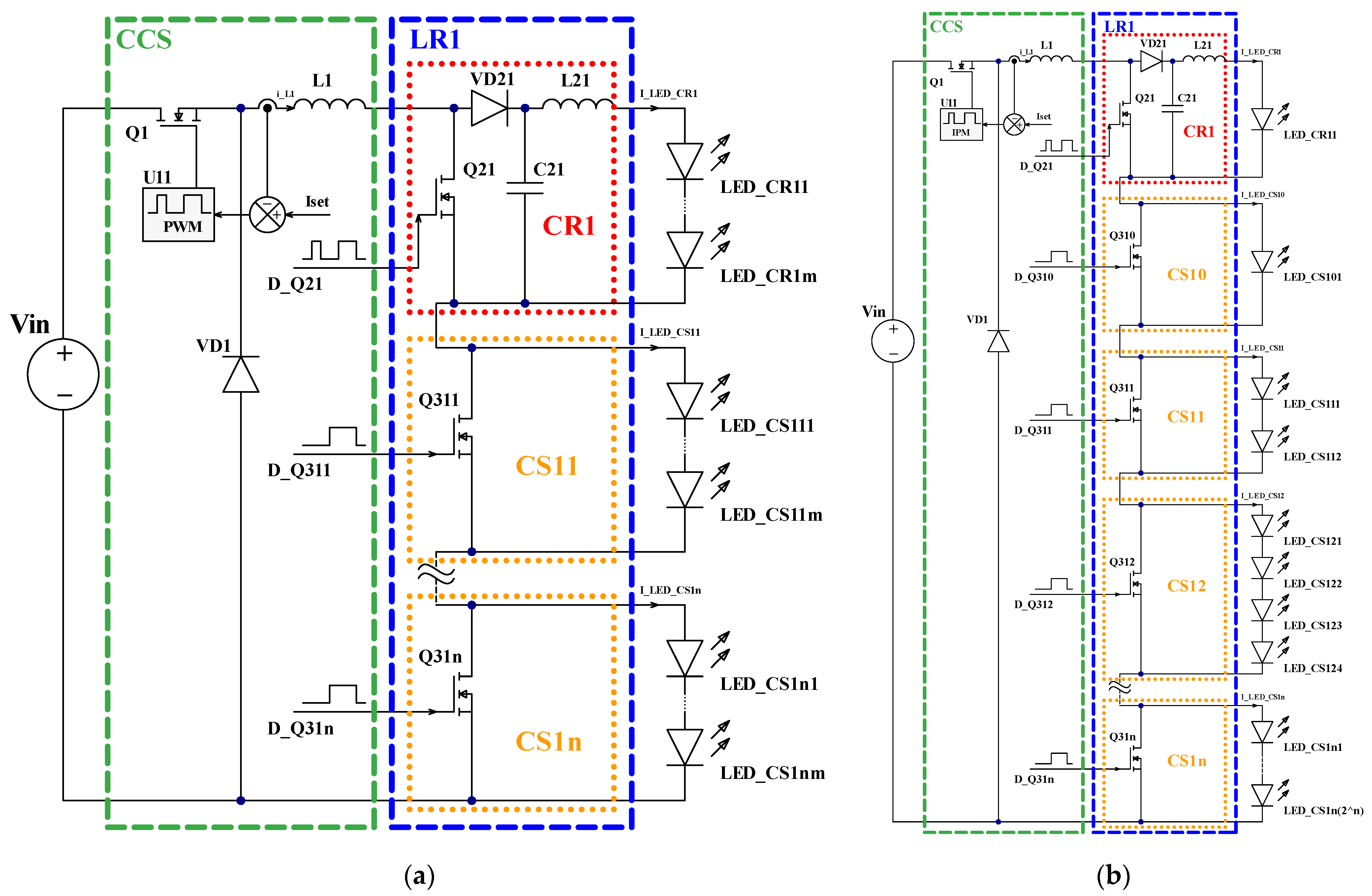
To distinguish the previous discussed CR concept from the new modified CR stage with parallel controlled switches, we introduce the name “light flux regulator” (LR) for this whole combination as well as “current switch” (CS) for parallel controlled switches inside this regulator. The implementation of light flux regulators LR1 for each regulated channel is shown in Figure 4a.
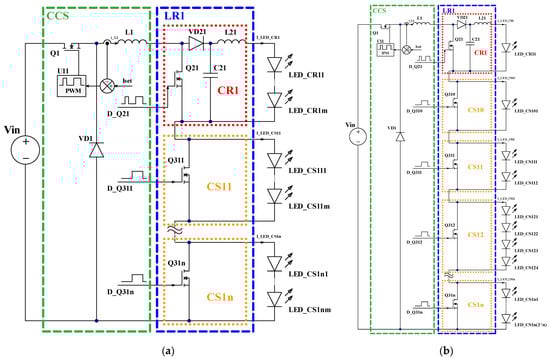
Figure 4.
Implementation of light flux regulator LR in CSM SIMO LED driver: (a) using the same LED numbers in light flux regulator LRx and current switch CSxy branches; (b) using binary-weighted LED numbers in light flux regulator LRx and current switch CSxy branches.
Each LR1 is constructed as a combination (series connection) of single current regulator CR1 and a chosen number of current switches CS1y, which are controllable switches Q31y connected in parallel with light-emitting diodes LED1y1 … LED1yz, where y is the numbering index for current switches, while z is the numbering index for LEDs. Current regulator CR1 consists of capacitor C21 connected in parallel with LED11 … LED1z, they are connected in series with an uncontrolled switch—diode VD21 (which in general, can also be a controllable switch). As mentioned previously, in comparison with the original CR circuit from [1], we use inductors L21 … L2k to show the inherent current source nature of the current regulator as shown in Figure 1 and in [2]. Controllable power switch Q21 is connected in parallel with all these components. Q21 is controlled by a pulse width modulation PWM signal. The average current value I_LED_CR1 of the CR1 branch of light diodes LED11 … LED1z depends on the value of the transistor Q21 control signal duty cycle D_Q21 and the constant current value I_L1, and is equal to [3]:
but the current value I_LED_CS1y of the CS1y branch of LED1y1 … LED1yz is either 0 or I_L1, depending on the specified value of the control parameter and the corresponding transistor Q31y control signal duty cycle D_Q31y.
I_LED_CR1 = I_L1·(1 − D_Q21),
As discussed above, the main aim for CR’s modification is efficiency improvement by modifying hardware parts as well as a light flux regulation control algorithm to bypass CR’s high-side diode over part of the regulation range with higher output power.
A simplified calculation for CR stage diode power loss and the efficiency curves were built for the bare CR stage and for the LR stage. The comparison is shown in Figure 5.
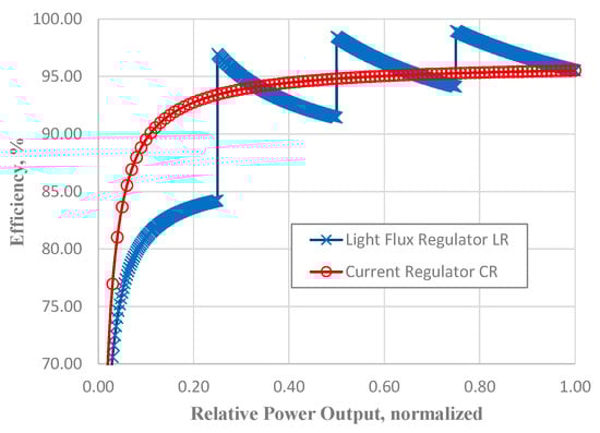
Figure 5.
Theoretical estimation of efficiency of bare CR stage and LR stage when driving the same number of LEDs.
It is seen from these graphs that there is better efficiency of the LR stage at a higher output power and worse results in a low power range in comparison with the bare CR stage because only the CR part operates in LR at low light outputs. To achieve better efficiency of the lamp, the light output control strategy for LR can be constructed in such a way that the CR part is involved only in fluent transitions between different brightness states.
5. Binary-Weighted LED Number in Separate LED Light Source Branches
To optimize the number of controllable switches in LR, it is possible to choose binary-weighted LED numbers in the CSxy branches according to the principle:
where x is the numbering index of LRs and CRs, y is the numbering index for CSs as mentioned previously, but m is the number of LEDs in the corresponding branch. Then, the last LED index in the CSxy branch is LED_CSxnm or LED_CSxn(2n) (Figure 4b).
mxy = 2y,
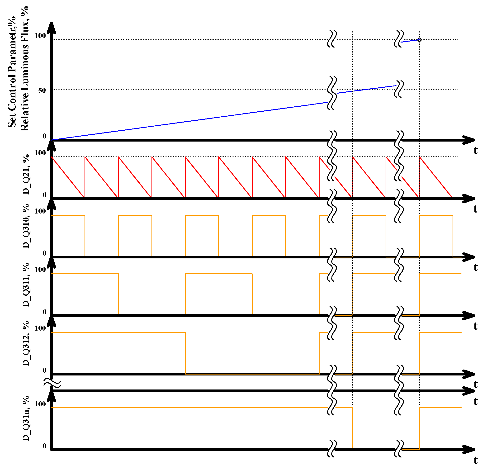
The light flux regulation algorithm as well as control signals of LR’s controllable switches for LR with four CSs and binary-weighted numbers of LEDs in these branches are shown in Figure 6.
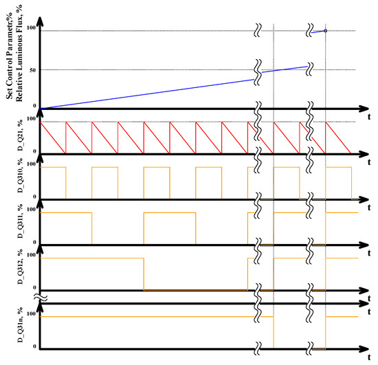
Figure 6.
Control strategy of light flux regulator LRx with binary-weighted number of LEDs in CSxy branches. Colors are consistent with Figure 4a: blue—relative luminous flux of whole LRx; red—duty cycle of control signal for CRx stage transistor; orange—control signals for CSxy.
The total luminous flux produced by LEDs is approximately proportional to the given control parameter. Control signals of power switches Q21, Q310 … Q31n are formed in accordance with the specified value of the control parameter. CR’s power switch Q21 is driven by the signal D_Q21, the duty cycle of this signal varies within the range of 0 to 100%. The duty cycle of control signals D_Q310 … DQ31n for power switches Q310 … Q31n are either 0% or 100%.
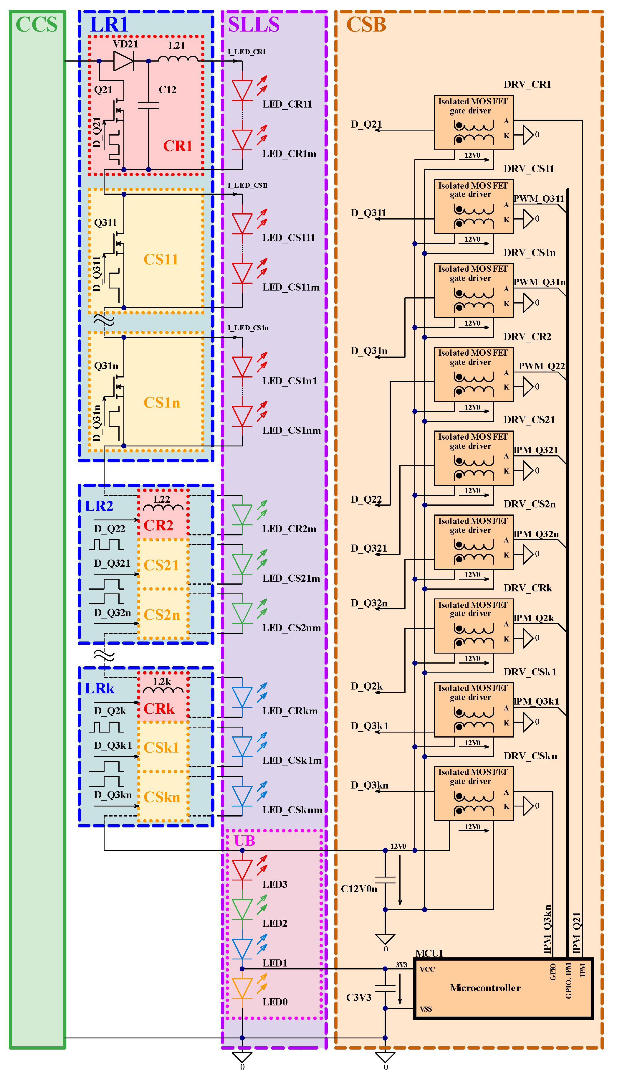
Configuration of the proposed SIMO driver for the general case is given in Figure 7. It consists of multiple LRx blocs for multi-channel regulation.
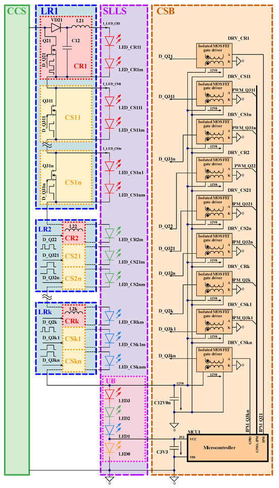
Figure 7.
General case configuration of proposed SIMO driver and SLLS with the uncontrolled branch for voltage extraction for CSB.
6. Considerations on Control Circuit Implementation
The main topic of this article is the discussion of the practical implementation of the SIMO LED driver and possible solutions for existing non-controllable LED lamps, upgrading them to regulated light color lamps using this driver.
As discussed above, the standard LED driver with minor modifications can be reconfigured to CCS suitable for use as part of the SIMO driver. In this way, part of the existing non-controllable LED lamp can be used. The problem with the power supplies of existing non-controllable LED systems is an absence of low-voltage output suitable for the supply of control circuits of the proposed SIMO driver: single current source output is available. One or several LEDs in a separate unregulated branch (UB) of the segmented LED light source (SLLS) can be used for the extraction of suitable voltage for the control system block (CSB) of the proposed SIMO driver from this current source (LED driver). The discussed principle is shown in Figure 7. Of course, this method leads to noticeable disadvantages: such a lamp will always produce a minimum luminous flux of a certain color light, specified by LEDs from the introduced UB of SLLS. However, the described approach of voltage extraction for the supply of control parts can be used in LED lighting applications, where this minimum output light drawback does not matter. This allows for the simplification of the lamp’s overall structure and for cost optimization.
LEDs in the unregulated LED branch LED0 … LED3 of SLLS function as a voltage stabilizer for both the microcontroller MCU1 at 3V0 and the isolated MOSFET drivers DRV_CR1 … DRV_CRk, DRV_CS11 … DRV_CSkn of power switches Q21 … Q2k, Q311 … Q3kn at 12V0. For the optimization of transistor driving circuits, the UB of a segmented LED light source can be split and located at the CCS’ both negative and positive nodes as well, and both type N-FET and type P-FET transistors can be used in this case.
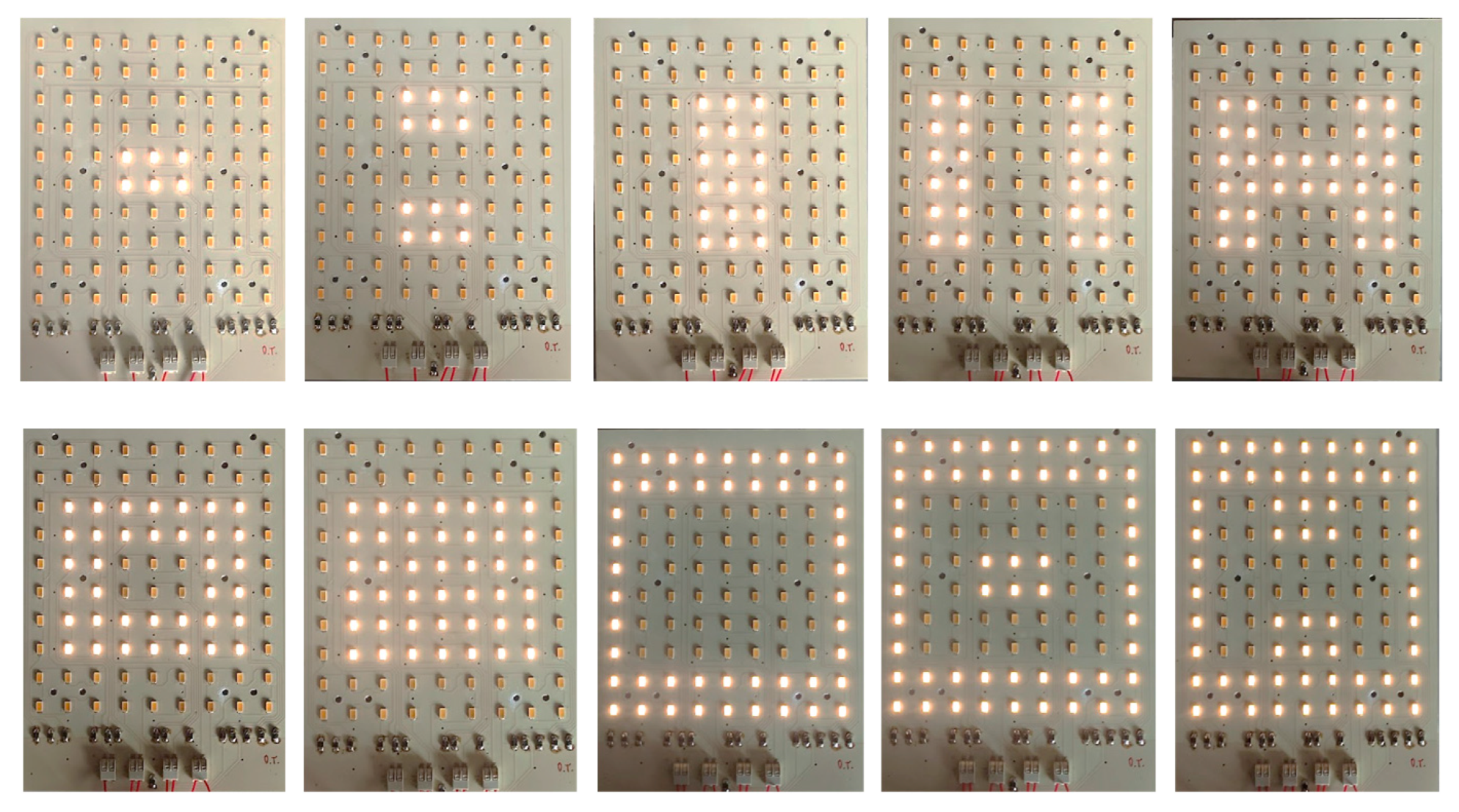
7. Considerations on LED Physical Placement for Segmented Light Sources
It is intended that with this type of driver, bi-color or multi-color LEDs will be used to obtain the best color mixing results. However, for the lighting applications where this issue is not critical, separate colored LEDs also can be used. As the light source has separate controllable branches, the LEDs should be placed symmetrically against the SLLS center for the most even light distribution results, as shown in the sample in Figure 8 with the binary-weighted number of LEDs in separate branches (not all combinations are shown: 10 of 15 possible combinations). This segmented module was built as one color/channel module, but it is applicable as a sample of possible implementation.

Figure 8.
Example of symmetrical placement of LEDs in SLLS with binary-weighted number of LEDs in separate branches.
8. Experimental Validation
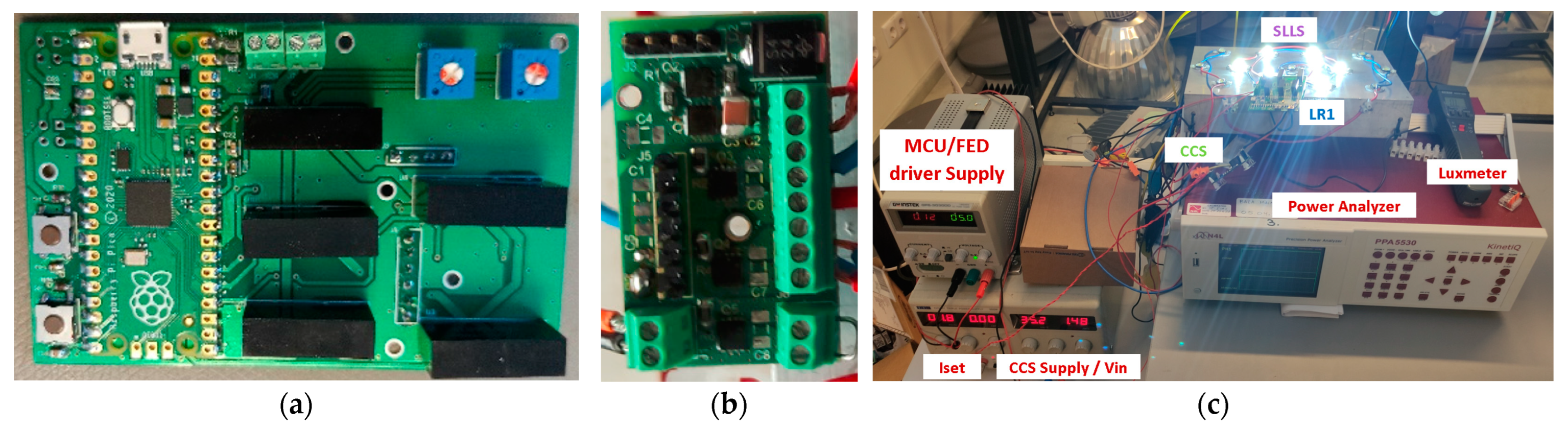
For experimental validation, the prototype of the proposed modified SIMO driver was built by combining CCS based on an MP24833 LED driver IC (Figure 3) and one LR stage. The LR for testing purposes was built on two separate stackable PCBs/boards, splitting the power part and control part (these PCBs/boards are shown in Figure 9).
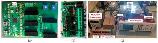
Figure 9.
The prototype of the proposed SIMO driver based on LR: (a) control and FET driver board; (b) power part board; (c) testing setup.
The LR stage (power part, which is shown in Figure 9b) of the prototype is configured as the combination of one current regulator CR1 with four current switches, CS0 … CS3. For testing purposes, the most robust FET driving circuit configuration was selected for implementation in the prototype board: isolated gate drivers with an isolated supply for each driver.
As the control system, the core of the proposed LR RP2040 microcontroller was selected. However, it could be any other microcontroller with enough configurable GPIOs: for this prototype, one PWM output and four GPOIs. For testing purposes, two control parameter input methods were implemented: (1) by trimmer and MCU readings of its set value on ADC input and (2) by “increase”/“decrease” push-buttons. A board of the control parts of the prototype is shown in Figure 9a.
The testing setup for the experimental validation of the proposed LR is shown in Figure 9c. Summaries of the initial tests are given in Figure 10 and Figure 11.
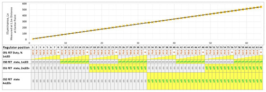
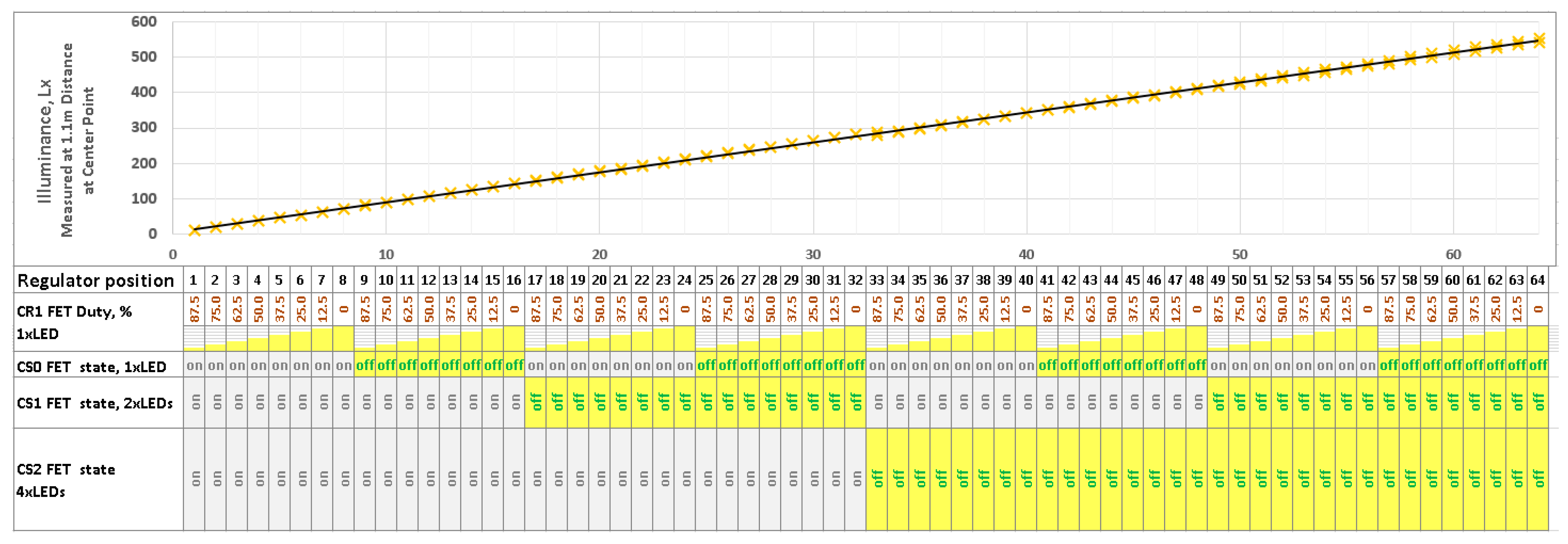
Figure 10.
Experimental validation of single LR stage: correspondence of control signals to the illuminance at center point below LED module at 1.1 m distance.
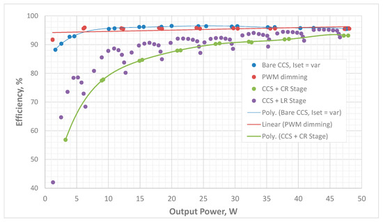
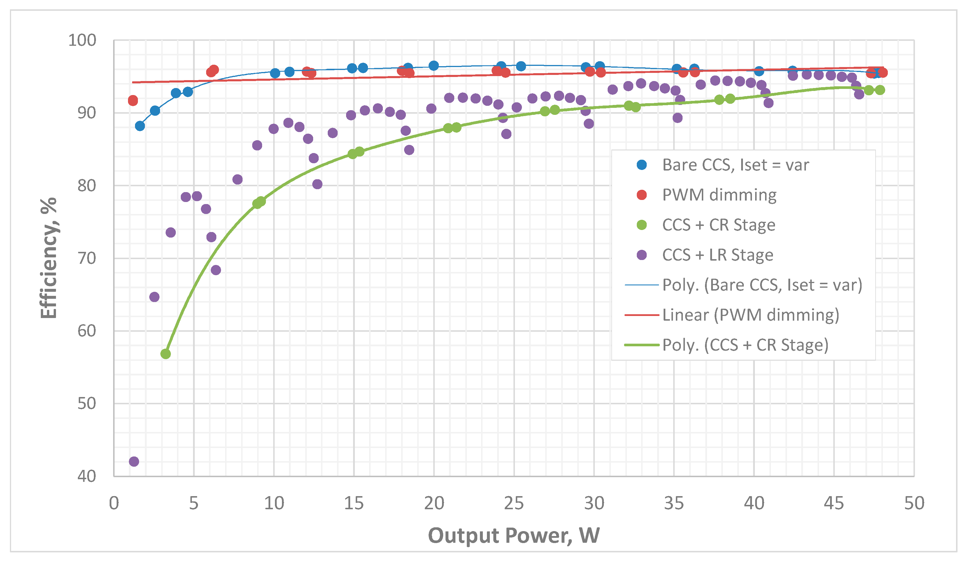
Figure 11.
Comparison of the efficiency of different dimmable system configurations by the assessment of experimental data at similar conditions.
The experimental validation of single LR stage luminous flux regulation is shown in Figure 10. The measurements were made with an indirect method using a luxmeter at the central point below the LED module. Correspondence of the control signals to the illuminance at the center point below the LED module at 1.1 m distance is shown here. The tests were conducted with the quite old (still in good condition), white, high-power LEDs available in the laboratory: Seoul Semiconductor W724C0 LEDs. The V–A and A–lm curves of a single LED of the mentioned type are given in [19]. The configuration of the module was made as shown in Figure 4b, except for the number of CS stages (three stages). The placement of LEDs is close to each other, but not perfectly symmetrical. Thus, the deviation of the experimental points across a linear interpolation is seen in Figure 10, close to the transition points when switching to the next CS combination state.
The assessment of the efficiency of the proposed system configuration is given in Figure 11. The tests for all dimming options were performed in similar conditions to the LED module mentioned above, with the maximum output power approximately 50 W using eight LEDs in total. Input voltage in all conducted experiments was the same, 35 V. The data obtained using Newtons4th Ltd. (Leicester, UK) PPA5530 precision power analyzer were used for this experimental efficiency validation. It is seen here that the efficiency of the bare CCS part is noticeably better in comparison with the combination of CCS+CR, which is the price for using such a kind of SIMO driver in high-power applications. However, as can be seen from Figure 11, some efficiency improvements can be achieved using the proposed configuration with light regulator stages.
9. Conclusions
The constant current mode SIMO LED driver is a good candidate for the implementation of a color regulation system for LED lamps partly based on existing, well-proven solutions. However, there are some issues with practical implementation: reduced efficiency in the current regulator stages and issues with the additional supply for the control part, as well as the necessity of using specially designed segmented LED light sources in combination with the SIMO driver. This article provides positively working solutions to all these issues described above.
The implementation of LR (Figure 4 and Figure 7) is proposed for improving the efficiency of regulators with theoretical estimation, as shown in Figure 5 and confirmed by experiments (Figure 10).
As the solution for the control part supply issue, it is proposed to use an additional uncontrolled LED branch by implementing this branch in the segmented LED light source.
Also, a feature of this driver that the SLLS with symmetrically arranged binary-weighted LED branches used can be utilized in a lamp as a visual design element, as can be seen from Figure 8.
Author Contributions
Conceptualization, I.G., O.T. and A.B.; methodology, I.G. and O.T.; software, A.B.; validation, O.T., I.G. and A.B.; formal analysis, O.T. and A.B.; investigation, I.G., O.T. and A.B.; resources, O.T. and I.G.; data curation, O.T. and A.B.; writing—original draft preparation, O.T.; writing—review and editing, I.G.; visualization, A.B.; supervision, I.G.; project administration, I.G.; funding acquisition, I.G. All authors have read and agreed to the published version of the manuscript.
Funding
This work was supported in part by the European Regional Development Fund (ERDF) under contract 1.1.1.1/20/A/079 “Research and Development of Two-Phase Thermal Systems Installed in Lighting Equipment for its Functional Improvement” of its Latvian measure 1.1.1.1 “Industry-Driven Research”. This work was supported in part by the European Regional Development Fund (ERDF) under contract Nr. 1.1.1.1/16/A/147 “Research and Development of Electrical, Information and Material Technologies for Low Speed Rehabilitation Vehicles for Disabled People” of its Latvian measure 1.1.1.1 “Industry-Driven Research”. 
Data Availability Statement
All the data presented in this study are summarized in this article.
Conflicts of Interest
The authors declare no conflict of interest.
References
- Dong, Z.; Tse, C.K.; Hui, S.Y.R. Current-Source-Mode Single-Inductor Multiple-Output LED Driver with Single Closed-Loop Control Achieving Independent Dimming Function. IEEE J. Emerg. Sel. Top. Power Electron. 2018, 6, 1198–1209. [Google Scholar] [CrossRef]
- Galkin, I.A. Simulation of Current Sourced Power Supply Providing Adjustable Currents for Multiple Loads. In Proceedings of the 2019 Electric Power Quality and Supply Reliability Conference (PQ) & 2019 Symposium on Electrical Engineering and Mechatronics (SEEM), Kärdla, Estonia, 12–14 June 2019; pp. 1–6. [Google Scholar] [CrossRef]
- Galkin, I.; Tetervjonok, O.; Milashevski, I. Comparative study of steady-state performance of voltage and current fed dimmable LED drivers. In Proceedings of the 2013 International Conference-Workshop Compatibility and Power Electronics, Ljubljana, Slovenia, 5–7 June 2013; pp. 292–297. [Google Scholar] [CrossRef]
- Galkin, I.; Tetervenoks, O.; Milashevski, I. Static losses and controllability of current fed dimmable LED drivers. In Proceedings of the 2013 15th European Conference on Power Electronics and Applications (EPE), Lille, France, 2–6 September 2013; pp. 1–10. [Google Scholar] [CrossRef]
- Galkin, I.; Tetervenoks, O. Validation of direct current control in LED lamp with non-inverting buck-boost converter. In Proceedings of the IECON 2013—39th Annual Conference of the IEEE Industrial Electronics Society, Vienna, Austria, 10–13 November 2013; pp. 6021–6026. [Google Scholar] [CrossRef]
- Dong, Z.; Li, X.L.; Tse, C.K.; Zhang, Z. Application of Current-Source-Mode Converters to Synthesis of Single-Input Dual-Output Regulators with No Cross Regulation. In Proceedings of the 2020 IEEE 9th International Power Electronics and Motion Control Conference (IPEMC2020-ECCE Asia), Nanjing, China, 29 November–2 December 2020; pp. 584–587. [Google Scholar] [CrossRef]
- Dong, Z.; Li, X.L.; Tse, C.K.; Zhang, Z. Derivation of Single-Input Dual-Output Converters with Simple Control and No Cross Regulation. IEEE Trans. Power Electron. 2020, 35, 11930–11941. [Google Scholar] [CrossRef]
- Li, X.L.; Dong, Z.; Tse, C.K. Complete Family of Two-Stage Single-Input Multioutput Configurations of Interconnected Power Converters. IEEE Trans. Power Electron. 2020, 35, 3713–3728. [Google Scholar] [CrossRef]
- Li, X.L.; Tse, C.K. Derivation of Complete Family of Multi-Output Configurations Including Voltage-Source-Mode and Current-Source-Mode Converters. In Proceedings of the 2019 IEEE International Symposium on Circuits and Systems (ISCAS), Sapporo, Japan, 26–29 May 2019; pp. 1–5. [Google Scholar] [CrossRef]
- Zu, A.; Luo, Q.; Huang, J.; He, Q.; Sun, P.; Du, X. Analysis and design of a multi-channel constant current LED driver based on DC current bus distributed power system structure. IET Power Electron. 2020, 13, 627–635. [Google Scholar] [CrossRef]
- Choi, S.; Kim, T. Symmetric Current-Balancing Circuit for LED Backlight with Dimming. IEEE Trans. Ind. Electron. 2012, 59, 1698–1707. [Google Scholar] [CrossRef]
- Chiu, C.-L.; Chen, K.-H. A high accuracy current-balanced control technique for LED backlight. In Proceedings of the 2008 IEEE Power Electronics Specialists Conference, Rhodes, Greece, 15–19 June 2008; pp. 4202–4206. [Google Scholar] [CrossRef]
- Thomas, W.; Pforr, J. Power-transfer of isolated converter with integrated power sharing for LED-lighting system dependent on transformer coupling. In Proceedings of the 2010 IEEE Energy Conversion Congress and Exposition, Atlanta, GA, USA, 12–16 September 2010; pp. 449–456. [Google Scholar] [CrossRef]
- Chen, H.; Zhang, Y.; Ma, D. A SIMO Parallel-String Driver IC for Dimmable LED Backlighting with Local Bus Voltage Optimization and Single Time-Shared Regulation Loop. IEEE Trans. Power Electron. 2012, 27, 452–462. [Google Scholar] [CrossRef]
- Li, S.; Guo, Y.; Tan, S.-C.; Hui, S.Y. An Off-line Single-Inductor Multiple-Output LED Driver with High Dimming Precision and Full Dimming Range. IEEE Trans. Power Electron. 2017, 32, 4716–4727. [Google Scholar] [CrossRef]
- Dong, Z.; Li, X.L.; Tse, C.K. Improved-efficiency quasi-two-stage current-source-mode SIMO LED driver. IET Power Electron. 2019, 12, 3286–3294. [Google Scholar] [CrossRef]
- Suganthi, K.; Sundararaman, K.; Nityanarayanan, C.; Thamarai Selvan, M.S.S.; Sudhakar, K.B. A Single-Inductor Multi-Output Current-Mode LED Driver with Soft-Switching. In Proceedings of the 2022 First International Conference on Electrical, Electronics, Information and Communication Technologies (ICEEICT), Trichy, India, 16–18 February 2022; pp. 1–8. [Google Scholar] [CrossRef]
- Monolithic Power Systems. MP24833-AGN-Z Datasheet. Available online: https://www.monolithicpower.com/en/documentview/productdocument/index/version/2/document_type/Datasheet/lang/en/sku/MP24833-AGN-Z/document_id/2070/ (accessed on 9 September 2023).
- Seoul Semiconductors, W724C0 Datasheet. 2008. Available online: https://mm.digikey.com/Volume0/opasdata/d220001/medias/docus/647/W724C0.pdf (accessed on 13 December 2023).

Disclaimer/Publisher’s Note: The statements, opinions and data contained in all publications are solely those of the individual author(s) and contributor(s) and not of MDPI and/or the editor(s). MDPI and/or the editor(s) disclaim responsibility for any injury to people or property resulting from any ideas, methods, instructions or products referred to in the content. |
© 2023 by the authors. Licensee MDPI, Basel, Switzerland. This article is an open access article distributed under the terms and conditions of the Creative Commons Attribution (CC BY) license (https://creativecommons.org/licenses/by/4.0/).