Abstract
This paper presents a miniaturized-structure high-gain antipodal Vivaldi antenna (AVA) operating in the millimeter-wave (mm-wave) band. A gradient-length microstrip-patch-based director is utilized on the flares of the AVA to enhance gain. Additionally, an array of metallic vias is incorporated along the lateral and horizontal edges of the antenna for further gain enhancement and bandwidth extension. Based on the proposed structure, the AVA can achieve a peak gain of 11.9 dBi over a relative bandwidth of 71.24% within 16.5–36.6 GHz as measured, while the electrical dimension is only 1.54 × 2.69 × 0.07 . The measured results show good agreement with the simulated ones. Owning the characteristics of being high-gain and ultra-wideband, and having a compact size, the proposed AVA can be a competitive candidate for future millimeter-wave communication.
1. Introduction
The proliferation of data-intensive applications on User’s Equipment (UE) has significantly augmented global mobile data traffic. However, the sub-6 GHz frequency bands employed in fourth-generation (4G) networks are insufficient to cater to such demands in wireless communication. Consequently, there is an imperative requirement to expand the bandwidth in millimeter-wave for next-generation communication [1]. Using millimeter-wave antennae as the front end of 5G communication systems can provide faster connections, ultra-low latency, and high data rates to meet different needs [2,3,4]. With operating frequency in modern communication systems continuing to increase, the demand for miniaturized end-fire antennae is also mounting. The end-fire antenna is the one that radiates with a directional and narrow beam pattern in the plane as the physical construction, which plays a key role in a wide range of modern-day communication scenarios such as airport dispatching and imaging system. However, the miniaturization design for antennae is often at the cost of the bandwidth and gain of the antenna. Therefore, how to improve the working bandwidth and gain of the antenna is of great significance in the miniaturized end-fire antenna design. In addition, several challenges need to be tackled when operating at the mm-wave band [5]. For instance, in order to overcome the high propagation loss, an antenna that is wideband, has stable radiation characteristics, and is high-gain is desirable. Among all candidates for mm-wave communication scenarios, the antipodal Vivaldi antenna (AVA) can be a prominent option because it inherently provides the characteristics of being wideband, and having a high gain and easy fabrication [6,7].
Nevertheless, achieving a compact-size and high-gain AVA while optimizing the design and performance remains a formidable challenge. The literature [8] shows that the various gain enhancement techniques are presented to enhance AVA performance. The dielectric lens has been used to enhance the front-to-back ratio (FBR) and gain by directing the majority of the energy in the end-fire direction [9,10,11]. Next, the typical parasitic metal patch presented in AVA flares also helps to improve the antenna gain and FBR [12]. In addition, metamaterial has been integrated with the Vivaldi antenna to obtain a high directivity and high gain. In [13], an ultra-wideband metamaterial-slab-covered AVA with a high gain is presented. However, the drawbacks of these designs are that either their size is too great, leading to a high fabrication cost, or the design process is complicated. Moreover, all the aforementioned gain-enhancing techniques is based on adding an extra component on the surface which is likely to result in a size increment. Nevertheless, very few investigations have been conducted on metallic vias to enhance the gain of the AVA.
In this paper, a miniaturized mm-wave AVA with a high gain and directivity is presented. For preliminary gain enhancement in all frequency bands, a director based on a variable-length microstrip patch is employed between the tapered slot. Next, an array of metallic vias is loaded on the AVA edges as perforation. It turns out that metallic via loading has an efficient gain-enhancing ability and can widen the operating bandwidth without increasing the overall size. The proposed AVA can operate within 16.5–36.6 GHz with a good radiation performance, and a peak gain of 11.9 dBi as measured. The designed AVA has an electrical dimension of 1.54 × 2.69 × 0.07 and good radiation performance. It means that high gain and miniaturization for the AVA are simultaneously realized in mm-wave frequency bands.
2. Geometrics and Antenna Design
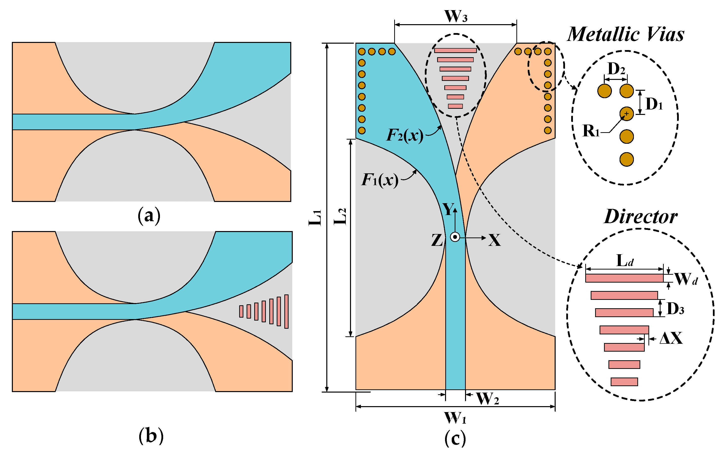
The proposed Vivaldi antenna (Ant III) and the other prototypes (Ant I and II) are all designed on the Rogers RT/duroid 5880, 0.787 mm. The antenna design parameters are shown in Table 1. The geometries and evolution process of the proposed antenna are depicted in Figure 1. The original antenna (Ant I) is an antipodal Vivaldi antenna with a double-sided structure and exponential tapered shape. The AVA loaded with a director is named Ant II and the proposed one on the right is named Ant III.

Table 1.
Design parameters and values of proposed AVA.
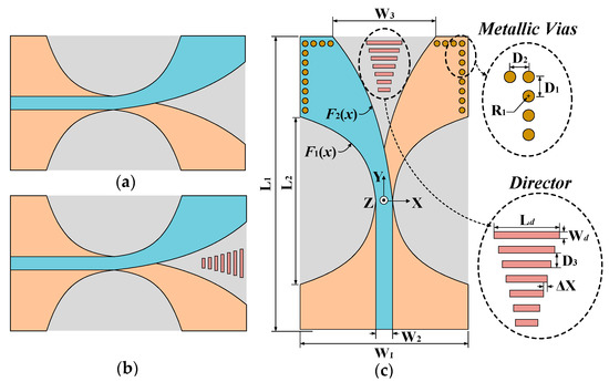
Figure 1.
Configuration of the AVAs: (a) Ant I, (b) Ant II, and (c) Ant III.
As is shown in Figure 1, the inner and outer edges of all of the AVAs are exponential curves defined in Equations (1) and (2), respectively:
where K1, K2 are the co-ordinates of each curve, and can be calculated by Equations (3) and (4), respectively:
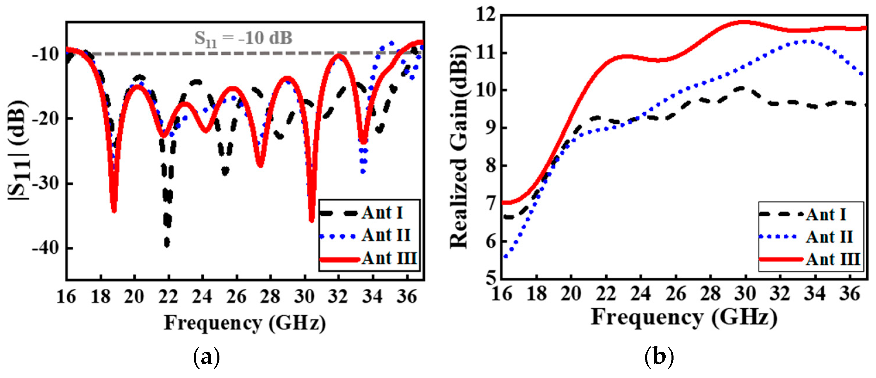
In order to clearly describe the design guideline of the proposed antenna, the evolution process is illustrated in Figure 1. The simulated realized gain of Ant I, II, and III is depicted in Figure 2b. As observed, the gain of Ant I is relatively low compared to Ant II and Ant III, which makes it difficult to meet the ever-demanding requirements for an end-fire antenna in future mm-wave communication [14,15]. Therefore, a director consisting of seven gradient-length microstrip patches is incorporated to boost the gain preliminarily.
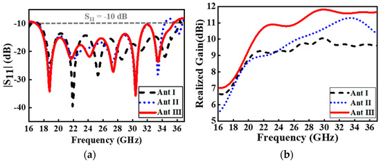
Figure 2.
Simulated (a) reflection coefficients and (b) gains of Ant I, II, and III.
The director is designed to be bilayered for structural symmetry and maintaining the low cross polarization of the AVA. A perspective view of the proposed director is shown in Figure 1c. The director consists of seven microstrip patches. Each of the patches has the same width but an evenly increased length. The aim of gradually increasing the length from the bottom to the top is to better match the propagating wavelength of the radiating electromagnetic wave corresponding to different radiating areas along the tapered slot for the AVA. As the basic transmission principle of the Vivaldi antenna indicates [16], different positions of the variable slot line radiate electromagnetic signals of different frequencies. In the AVA, the narrower region of the tapered slot radiates a high-frequency signal, while the wider radiates a low-frequency signal. Therefore, in order to maximize the energy coupled to the director in all frequency bands, the length of each microstrip element must increase accordingly as the tapered slot becomes wider, which can also counter the phase reversal to maintain a 180° phase difference between the current components on the conducting layer and the ground layers [17].
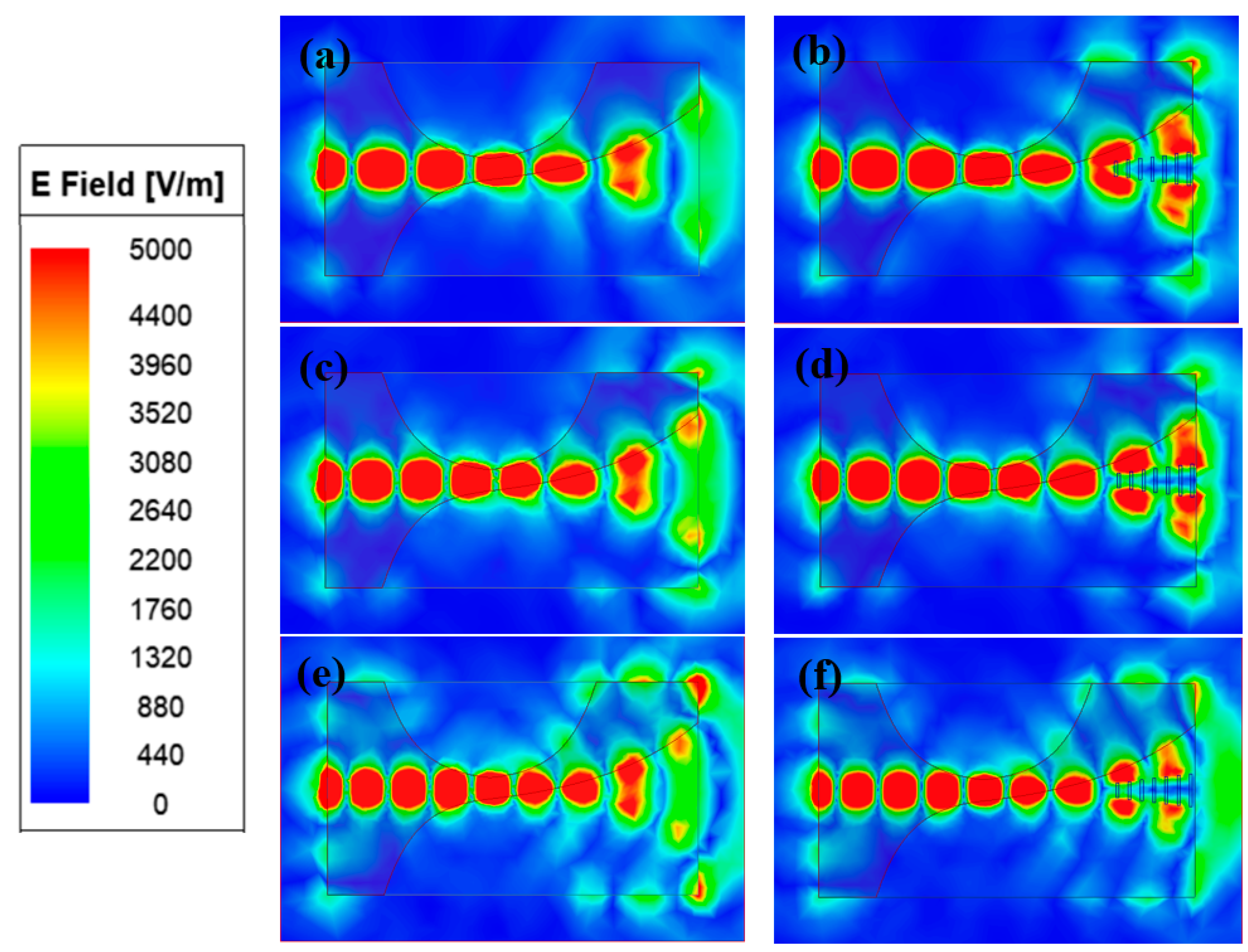
As depicted in Figure 3, employing a director with the proposed structure provides a different propagation environment on the antenna aperture. Extra electromagnetic energy is coupled to the director between two arms of the AVA so that the radiation beam can be better focused in the end-fire direction. From the presented results in Figure 2b, it is observed that the gain is effectively improved when the director is introduced, especially at higher frequencies. It is noted that the simulated realized gain of Ant II has a similar trend as Ant I, but there is a substantial gain enhancement near 2 dBi around 33 GHz. Compared with Ant I, the gain of Ant II with the director is further improved beyond 23 GHz with a simple director configuration.
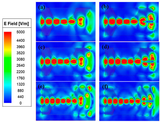
Figure 3.
Simulated E-field distribution on surface with (b,d,f) and without (a,c,e) director at 22 GHz, 26 GHz, and 30 GHz, respectively.
However, due to the input impedance change caused by loading the director, Ant II operates at a lower cut-off frequency at 34.6 GHz. In order to overcome the drawback for achieving a higher gain and wider bandwidth without increasing the size, a series of metallic vias has been placed in tandem on each edge of the AVA as perforation. The neighboring metallic vias have a radius of 0.3 mm and are separated by 1 mm. The simulated return loss (|S11|) for the proposed antenna is depicted in Figure 2a. After loading the metal vias, the original current path is interrupted, which can induce extra resonances and broaden the AVA’s impedance bandwidth [18]. It can also be explained that adding metallic vias on both side edges of the AVA will increase the electrical length of the antenna, leading to expending the bandwidth at a high operating frequency [19]. As seen in Figure 2a, the proposed AVA (Ant III) operates from 16.9 GHz but to a higher cut-off frequency of 35.6 GHz compared to Ant II, which means the impendence bandwidth is broadened.
The distribution of electromagnetic energy in a conventional Vivaldi antenna is not limited solely to the tapered slot, but can also extend to the radiating arms, resulting in undesired scattered radiation. This presents a challenge for achieving high-gain and high-directivity characteristics since concentrated electromagnetic energy is primarily required within the tapered slot region.
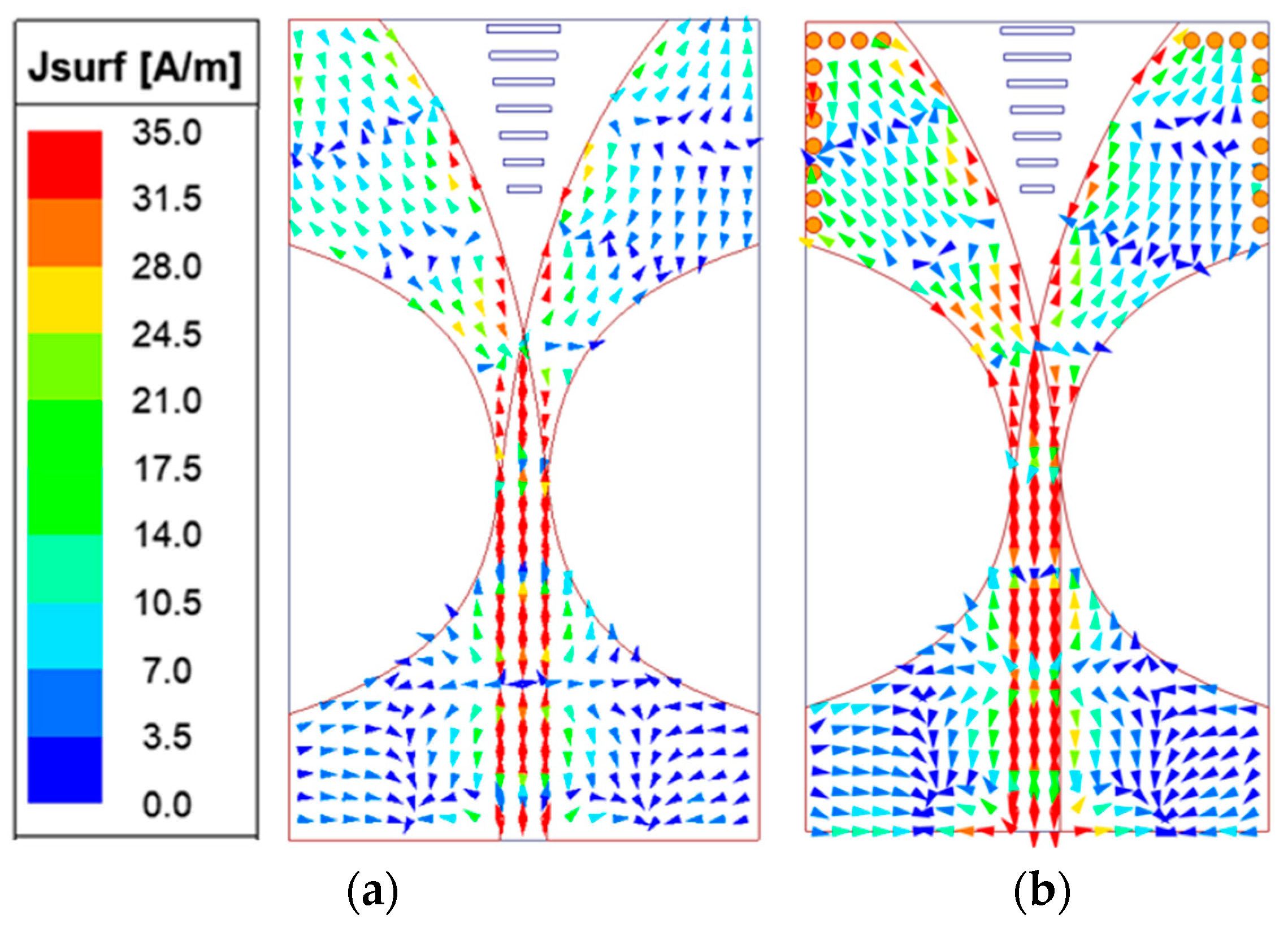
In order to analyze the characteristics of the metal through hole to improve the gain, the surface current distribution of the antenna at 26 GHz is mapped. As depicted in Figure 4, periodically loaded metallic vias perform like a perfect conductor (pec) boundary condition, forcing the electromagnetic energy to distribute majorly in the main radiation region. It can be noticed that the magnitude of the surface current vector has increased along the taper slot, which means more energy has focused in the main radiating direction as shown in Figure 4. It can be clearly seen that a significant gain enhancement within all operating bands can be achieved as shown in Figure 2b. It should also be noted that the realized gain of Ant III is increased by 1.8 dBi at the maximum, reaching 11.8 dBi at 31 GHz when operating with a wider bandwidth of 16.9–35.6 GHz as simulated.
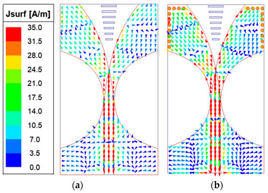
Figure 4.
Surface current distribution at 26 GHz: (a) Ant II and (b) Ant III.
The presented gain-boosting technique enables the proposed AVA to operate with a wider bandwidth and higher gain, while maintaining its original overall size. Consequently, this approach achieves simultaneous high gain and miniaturization in the mm-wave band antenna design.
3. Discussion of Measurements and Fabrication Results
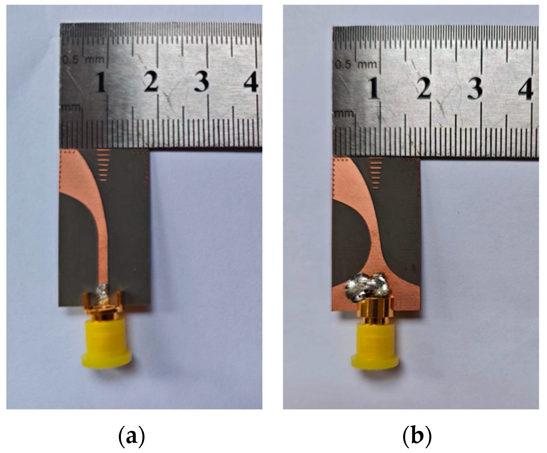
In order to evaluate the performance of the proposed AVA, a prototype is fabricated and measured as shown in Figure 5.
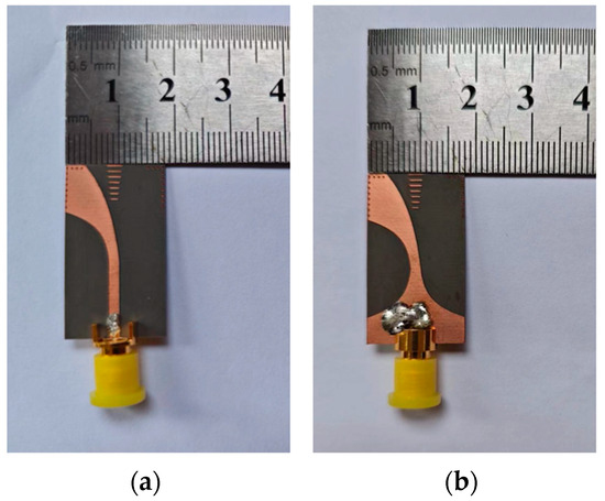
Figure 5.
Photograph of the fabricated antenna: (a) front view and (b) back view.
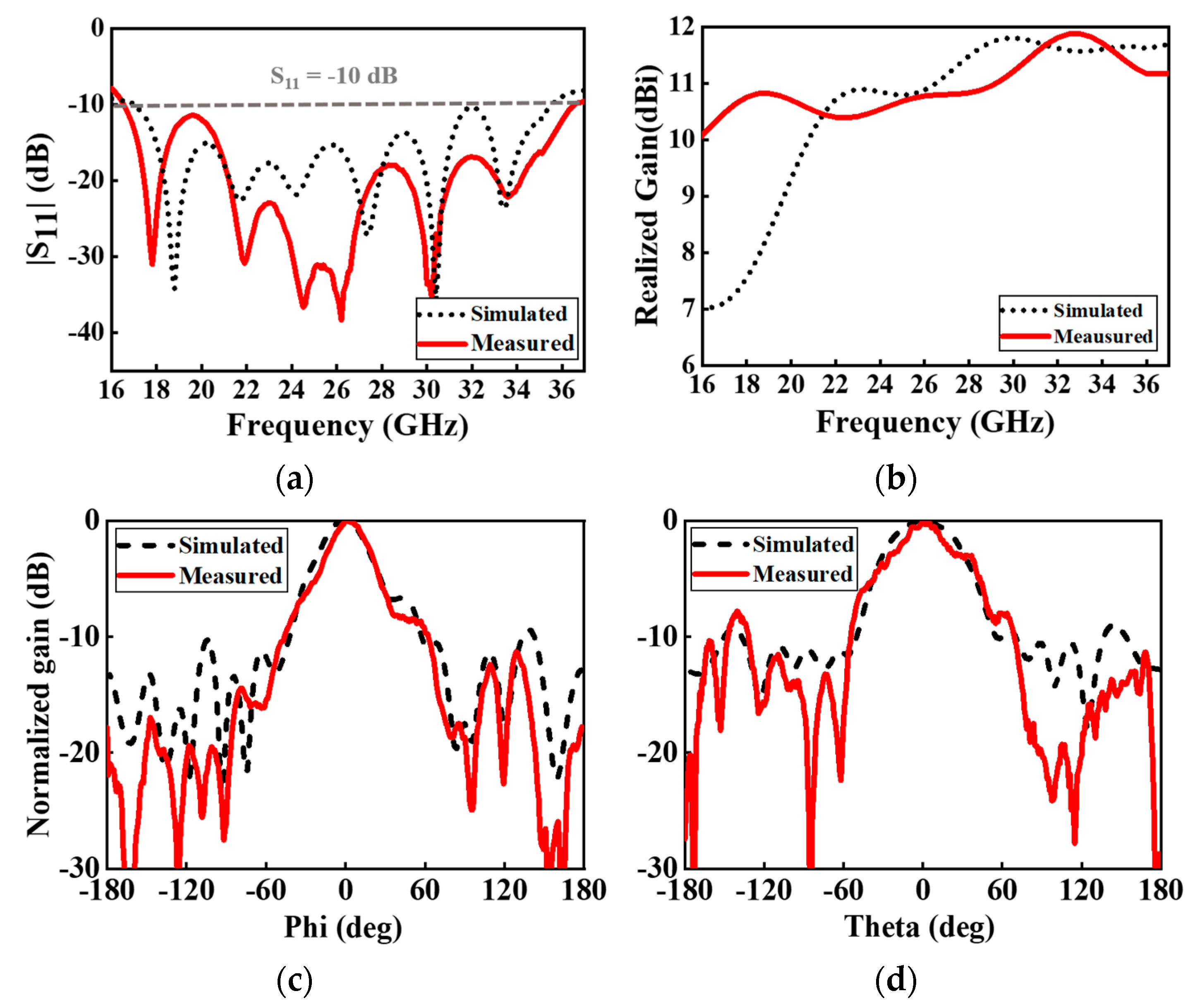
As shown in Figure 6a, the fabricated AVA achieves excellent impedance matching within 16.5–36.6 GHz, which also indicates that the operating band has slightly shifted to a lower frequency resulting from the variation of the dielectric constant of the fabricated substrate. The measured reflection coefficient is lower than −20 dB at 22–27 GHz and lower than −15 dB at 21–36 GHz. The measured and simulated radiation patterns of the proposed AVA at 26 GHz are illustrated in Figure 6c,d. As plotted, a stable radiation pattern with a narrow main lobe, low back lobe, and side lobe level both in the E-plane and H-plane at 26 GHz is obtained both in the simulated and measured plot. As for the realized gain measurement, a good agreement between the simulated and measured results is observed in the higher-frequency bands. Due to the frequency shift caused by the fabrication and test error mentioned above, the peak appearing in 23 GHz shifts to a lower frequency, which coincides with Figure 6a as it indicates that the lower cut-off frequency deviates to a lower frequency band. The measured gain is 9.8–11.9 dBi at 16.5–36.6 GHz where the peak gain reaches 11.9 dBi at 33 GHz.
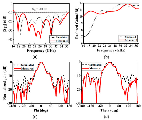
Figure 6.
Measured and simulated results of (a) reflection coefficients, and (b) gain and radiation pattern on (c) E-plane and (d) H-plane at 26 GHz.
A comparison of the proposed AVA with other works is listed in Table 2, where λc is the wavelength in the free space corresponding to the central operating frequency. As indicated, the proposed AVA in this paper is comparable with the other recently published work in terms of different performances. Compared with the MIMO 4 × 1 Vivaldi antenna, using a bi-axial metasurface in [20], the proposed single-element AVA achieves an even wider bandwidth and a much more compact size, as well as a higher gain in the mm-wave band. As compared with the antenna in [21], a wider bandwidth and much higher gain is achieved in mm-wave but at the cost of a less compact size. As compared with the metasurface-loaded Vivaldi antenna array in [22], the proposed AVA structure can operate within a wider bandwidth with a comparable gain in the mm-wave band without forming an antenna array. The wideband-filtering Vivaldi antenna using a metasurface in [23] has the advantages of a more compact size, but at the expense of a lower gain and narrower bandwidth in the mm-wave band compared to the AVA presented in this paper. In conclusion, the proposed AVA offers a comparatively high gain all over the ultra-wide mm-wave band with a relatively compact size among all these works.

Table 2.
The comparison of the proposed AVA with other works.
4. Conclusions
In this paper, a broadband mm-wave metallic-via-and-director-loaded AVA with a miniaturized size is proposed. The proposed director is designed for maximizing the energy radiated in the end-fire direction to boost gain. A series of metallic vias has been loaded along the lateral and horizontal edges as perforation for gain enhancement and bandwidth extension. The measured results demonstrate that the antenna achieves a maximum gain of 11.9 dBi at 33 GHz, and 9.8–11.9 dBi in the ultra-wide frequency band ranging from 16.5 to 36.6 GHz, while the electrical dimension is only 1.54 × 2.69 × 0.07 . The fabricated AVA was finally subjected to measurement. Despite a slight frequency shift resulting from fabrication and measurement errors, the excellent agreement observed between the simulated and measured outcomes demonstrates the promising potential of the proposed AVA for millimeter-wave communication.
Author Contributions
Conceptualization, J.L and J.H; methodology, J.L and J.H.; validation, J.L., J.H. and H.H.; investigation, J.L and J.H; writing—original draft preparation, J.H.; writing—review and editing, J.L., J.H. and H.H; supervision, Y.W.; funding acquisition, J.L. All authors have read and agreed to the published version of the manuscript.
Funding
This work was supported by the Climbing Program of Guangdong Province under Grant No. pdjh2023a0024 and pdjh2024b039.
Data Availability Statement
The data that support the findings of this study are available within the article.
Conflicts of Interest
The authors declare no conflicts of interest.
References
- Al-Shammari, B.K.J.; Hburi, I.; Idan, H.R.; Khazaal, H.F. An Overview of mm-Wave Communications for 5G. In Proceedings of the 2021 International Conference on Communication & Information Technology (ICICT), Basrah, Iraq, 5–6 June 2021; pp. 133–139. [Google Scholar]
- Juneja, S.; Pratap, R.; Sharma, R. Study of Two Design Variations of an Antipodal Vivaldi Antenna Working at 28 GHz Millimeter Wave Frequency for 5G Applications. In Proceedings of the 2022 IEEE 2nd Mysore Sub Section International Conference (MysuruCon), Mysuru, India, 16–17 October 2022; pp. 1–5. [Google Scholar]
- Huang, G.-L.; Pang, Z.-Y.; Al-Nuaimi, M.K.T.; Kishk, A.A.; Mahmoud, A. A Broadband and High Aperture Efficiency Multilayer Transmitarray Based on Aperture-Coupled Slot Unit Cells. IEEE Trans. Antennas Propag. 2023, 71, 9633–9642. [Google Scholar] [CrossRef]
- Zhu, S.; Liu, H.; Chen, Z.; Wen, P. A Compact Gain-Enhanced Vivaldi Antenna Array with Suppressed Mutual Coupling for 5G mm-Wave Application. IEEE Antennas Wirel. Propag. Lett. 2018, 17, 776–779. [Google Scholar] [CrossRef]
- Honari, M.M.; Ghaffarian, M.S.; Mirzavand, R. Miniaturized Antipodal Vivaldi Antenna with Improved Bandwidth Using Exponential Strip Arms. Electronics 2021, 10, 83. [Google Scholar] [CrossRef]
- Liu, H.; Yang, W.; Zhang, A.; Zhu, S.; Wang, Z.; Huang, T. A Miniaturized Gain-Enhanced Antipodal Vivaldi Antenna and Its Array for 5G Communication Applications. IEEE Access 2018, 6, 76282–76288. [Google Scholar] [CrossRef]
- Parveen, F.; Wahid, P. Design of Miniaturized Antipodal Vivaldi Antennas for Wideband Microwave Imaging of the Head. Electronics 2022, 11, 2258. [Google Scholar] [CrossRef]
- Umar, S.M.; Khan, W.-U.-R.; Ullah, S.; Ahmad, F. Gain Enhancement Technique in Vivaldi Antenna For 5G Communication. In Proceedings of the 2019 2nd International Conference on Computing, Mathematics and Engineering Technologies (iCoMET), Sukkur, Pakistan, 30–31 January 2019; pp. 1–4. [Google Scholar]
- Wan, F.; Chen, J.; Li, B. A Novel Ultra-wideband Antipodal Vivaldi Antenna with Trapezoidal Dielectric. Microw. Opt. Technol. Lett. 2018, 60, 449–455. [Google Scholar] [CrossRef]
- Amiri, M.; Tofigh, F.; Ghafoorzadeh-Yazdi, A.; Abolhasan, M. Exponential Antipodal Vivaldi Antenna with Exponential Dielectric Lens. IEEE Antennas Wirel. Propag. Lett. 2017, 16, 1792–1795. [Google Scholar] [CrossRef]
- Cicchetti, R.; Cicchetti, V.; Faraone, A.; Testa, O. A Class of Lightweight Spherical-Axicon Dielectric Lenses for High Gain Wideband Antennas. IEEE Access 2021, 9, 151873–151887. [Google Scholar] [CrossRef]
- Shi, X.; Cao, Y.; Hu, Y.; Luo, X.; Yang, H.; Ye, L.H. A High-Gain Antipodal Vivaldi Antenna with Director and Metamaterial at 1–28 GHz. IEEE Antennas Wirel. Propag. Lett. 2021, 20, 2432–2436. [Google Scholar] [CrossRef]
- Li, X.; Zhou, H.; Gao, Z.; Wang, H.; Lv, G. Metamaterial Slabs Covered UWB Antipodal Vivaldi Antenna. IEEE Antennas Wirel. Propag. Lett. 2017, 16, 2943–2946. [Google Scholar] [CrossRef]
- Liu, L.; Jiang, Y.; Hu, Y.; Jiang, D.; Zhu, L. Wideband Millimeter-Wave Endfire Antenna Based on Symmetrical Spoof Surface Plasmon Polaritons. IEEE Trans. Antennas Propag. 2021, 69, 7386–7393. [Google Scholar] [CrossRef]
- Zhang, X.-F.; Sun, W.-J.; Chen, J.-X. Millimeter-Wave ATS Antenna with Wideband-Enhanced Endfire Gain Based on Coplanar Plasmonic Structures. IEEE Antennas Wirel. Propag. Lett. 2019, 18, 826–830. [Google Scholar] [CrossRef]
- Gibson, P.J. The Vivaldi Aerial. In Proceedings of the 1979 9th European Microwave Conference, Brighton, UK, 17–20 September 1979; pp. 101–105. [Google Scholar]
- Sandhana Mahalingam, M.; Pandeeswari, R.; Ko, S.; Kouki, A.B. A Compact Balanced Antipodal Vivaldi Antenna with Improved Phase Center Stability for Imaging and Ultrawideband Localization Applications. AEU-Int. J. Electron. Commun. 2023, 170, 154844. [Google Scholar]
- Li, J.; He, H.; Xiong, S.; Feng, G.; Wang, Y. A Novel High-gain Antipodal Vivaldi Antenna for 5G MM-wave Applications. AEU-Int. J. Electron. Commun. 2024, 177, 155160. [Google Scholar] [CrossRef]
- Thaiwirot, W.; Kamoldej, D.; Detchporn, P.; Thongdit, R.; Tangwachirapan, S. Design of Ultra-Wideband and Constant Gain Antipodal Vivaldi Antenna with Corrugations. In Proceedings of the 2022 International Electrical Engineering Congress (iEECON2022), Khon Kaen, Thailand, 9–11 March 2022. [Google Scholar]
- Singh, M.; Parihar, M.S. Gain Improvement of Vivaldi MIMO Antenna with Pattern Diversity Using Bi-Axial Anisotropic Metasurface for Millimeter-Wave Band Application. IEEE Antennas Wirel. Propag. Lett. 2023, 22, 621–625. [Google Scholar] [CrossRef]
- Azari, A.; Skrivervik, A.; Aliakbarian, H.; Sadeghzadeh, R.A. A Super Wideband Dual-Polarized Vivaldi Antenna for 5G mmWave Applications. IEEE Access 2023, 11, 80761–80768. [Google Scholar] [CrossRef]
- Zhu, S.; Liu, H.; Wen, P. A New Method for Achieving Miniaturization and Gain Enhancement of Vivaldi Antenna Array Based on Anisotropic Metasurface. IEEE Trans. Antennas Propag. 2019, 67, 1952–1956. [Google Scholar] [CrossRef]
- Qi, H.; Liu, H. Wideband high-gain filtering Vivaldi antenna design based on MS and herringbone SSPP structure. IEEE Antennas Wirel. Propag. Lett. 2023, 22, 1798–1802. [Google Scholar] [CrossRef]
Disclaimer/Publisher’s Note: The statements, opinions and data contained in all publications are solely those of the individual author(s) and contributor(s) and not of MDPI and/or the editor(s). MDPI and/or the editor(s) disclaim responsibility for any injury to people or property resulting from any ideas, methods, instructions or products referred to in the content. |
© 2024 by the authors. Licensee MDPI, Basel, Switzerland. This article is an open access article distributed under the terms and conditions of the Creative Commons Attribution (CC BY) license (https://creativecommons.org/licenses/by/4.0/).

