Article

Circularly Polarized 4 × 4 Array Antenna with a Wide Axial Ratio Bandwidth

1
Department of Electrical and Electronic Engineering, Yuhan University, Bucheon 14780, Republic of Korea
2
Department of Information and Communication Engineering, Dongshin University, Naju 58245, Republic of Korea
3
Department of Information and Communication Engineering, Hanbat National University, Daejeon 34158, Republic of Korea
*
Authors to whom correspondence should be addressed.
Electronics 2024, 13(11), 2076; https://doi.org/10.3390/electronics13112076
Submission received: 15 April 2024 / Revised: 19 May 2024 / Accepted: 23 May 2024 / Published: 27 May 2024
(This article belongs to the Special Issue State-of-the-Art of Smart MIMO Antennas)

Abstract

:
In this manuscript, we propose a circularly polarized (CP) antenna design that can achieve broadband axial ratio (AR) bandwidth in the X-band. A sequentially rotated serial feeding network is applied to achieve the broadband requirement. The proposed antenna consists of two substrates, one is for feeding elements and the other is for radiating elements. The 16 radiating elements located on an upper substrate are fed through cross-shaped slots located in a ground plane between two substrates. The feed network is based on a 1:4 power divider design and consists of a serial connection of the power dividers resulting in the proper power splitting to the 16 radiating elements. The proposed antenna is designed to exhibit an optimal radiation characteristic of around 8.2 GHz with a CP antenna gain greater than 16 dB and similarly wide impedance and AR bandwidths. Experiments with the fabricated CP antenna were performed to support the proposed CP antenna design theory and are in good agreement with the simulation results.

1. Introduction

Circularly polarized (CP) antennas are increasingly gaining attention from both academic and commercial sectors due to their attractive radiation characteristics, such as better immunity to multi-path distortion and improved alignment between communication antennas compared to linearly polarized (LP) antennas. Due to their advantages, CP antennas have been widely adopted in various wireless communication applications such as wireless local area network (WLAN), Bluetooth, worldwide interoperability for microwave access (WiMAX), radio frequency identification (RFID), automatic dependent surveillance–broadcast (ADS-B), and global navigation satellite system (GNSS) [1,2,3,4,5]. Many kinds of CP antennas have been extensively reported about in recent years, designed to meet specific requirements, such as small form factors, dual-polarization, multi-band capabilities, and broader CP operation bandwidths [6,7,8,9,10,11,12,13,14,15,16]. In [9,10], CP antennas employing conventional slot-loaded microstrip patches fed by coplanar waveguide lines are discussed, but these can hardly be selected for the modern broadband communication due to the limitations of the CP bandwidth, even with advantages such as simple structures and low fabrication costs.
Many CP antennas with enhanced capabilities, particularly in terms of broad 3 dB AR bandwidth and suitable antenna gain, have been reported. Various shapes of crossed dipoles have been utilized to meet these requirements [11,12,13,14,15]. Miniaturized uniplanar crossed dipole structure has demonstrated approximately 50% impedance and AR bandwidth at 4 GHz with a peak gain of 2 dBic [11], and a CP antenna with a substrate integrated waveguide feed network was reported with about 30% CP bandwidth and greater than 20 dB port-to-port isolation characteristic [12]. To further improve the AR bandwidth, a non-planar reflector structure was employed, showing more than 120% impedance and AR bandwidth with 9.45 dBi gain [13]. In addition, in array antenna designs that achieve CP characteristics, the sequentially rotated feed network can be used to provide improved input impedance matching over the wider bandwidth [14,15,16,17,18,19,20]. The sequential rotation of radiating elements can yield polarization purity and symmetric radiation patterns, and due to the phase shift from the feed network, the reflections and delays from mismatched elements tend to cancel out at the feed point as well. Compared with the conventional cooperate feed network, the antenna array with sequential feeding also features less complexity with a small size.
In this article, a 4 × 4 array CP antenna with a broadband AR bandwidth is proposed based on the simple microstrip patch elements. The reflector structure, commonly incorporated into the previously published cross-dipole-based CP antenna, is excluded in order to achieve a simpler structure, as it may limit the proposed antenna from being used in applications that require a planar or compact form factor. The proposed antenna is designed to exhibit greater than 15 dBic of gain with 4 × 4 radiating elements and is fed by the sequentially rotated serial feed network, which has the improved off-center frequency characteristic. The proposed simple and compact structure can be mounted on micro-satellites or CubeSats as a part of the data communication devices [21,22]. The proposed CP antenna design achieves an impedance and AR bandwidth of approximately 3 GHz (from 7.0 GHz to 10.0 GHz), with a peak gain exceeding 16 dBic and an AR value less than 0.5 dB at the 8.2 GHz center frequency. The measurement results align well with the design theory and simulation results. The detailed design process of the radiating unit element and the feed network is presented in the next section, accompanied by simulation results. In Section 2, the design process from a radiating unit to a complete 4 × 4 CP array antenna is described in detail, and it is supported by experimental results of a fabricated antenna in Section 3.

2. CP Antenna Design

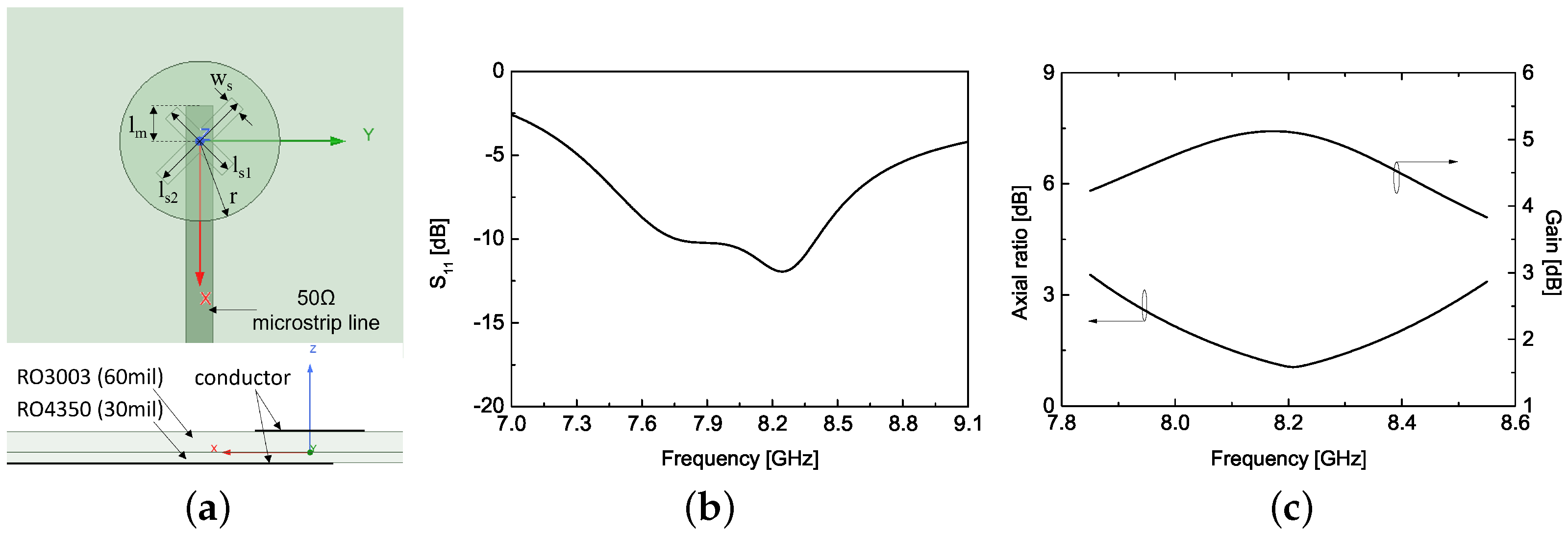
2.1. Radiating Element Design

In this subsection, a detailed design process of the unit radiating element is described. The conventional method to achieve circular polarization characteristics has been applied to the radiating element design [23]. The proposed antenna comprises two different substrates: one for the feed network and another for the radiating elements. These substrates are coupled by cross-shaped coupling slots placed between them. As shown in Figure 1a, a 50 Ω feed line is positioned on the bottom of the 30 mil thick RO4350 substrate, and a circular shaped patch designed to radiate at the operating frequency of 8.2 GHz is etched on the top of the 60 mil thick RO3003 substrate.
The parameter study to obtain the appropriate CP radiating characteristic was conducted using the design parameters shown in Figure 1a and the results are presented in Figure 2. It should be noted that a finite element method-based simulation tool, Ansys Electronics Desktop 2021 R2, was used to verify the performance of the proposed antenna design. Figure 1a, Figure 3a and Figure 5a directly depict the configurations of the simulations, and the results from each configuration are presented in the same figures. The radius of a circular patch can significantly change the operating frequency, and the cross-shaped slot placed in the ground plane of the patch can precisely tune the resonant frequency of two orthogonal modes. This results in changes to the circular polarization characteristics, as shown in Figure 2c,d. The electric field strength around the coupling slot can also be tuned by changing the electrical length between the coupling slot and the open-circuited end, a dimension denoted as l m . Figure 2b shows the impedance matching changes with the various l m values. As a result of the parameter study, the simulation results of the impedance matching, axial ratio, and antenna gain of the unit radiating element with the fine-tuned dimensions are shown in Figure 1b,c. The optimized dimensions are presented in the caption of Figure 1.

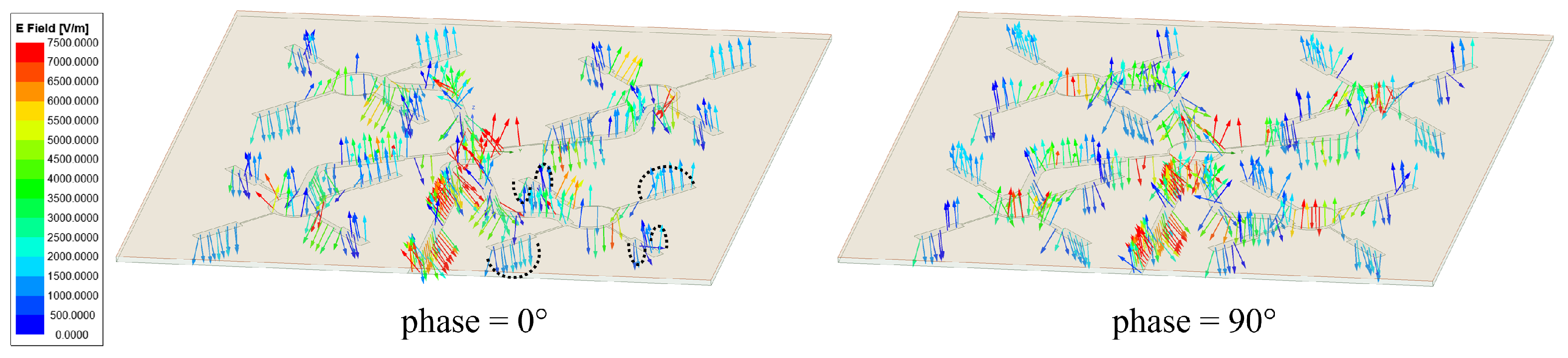
2.2. Feed Network Design
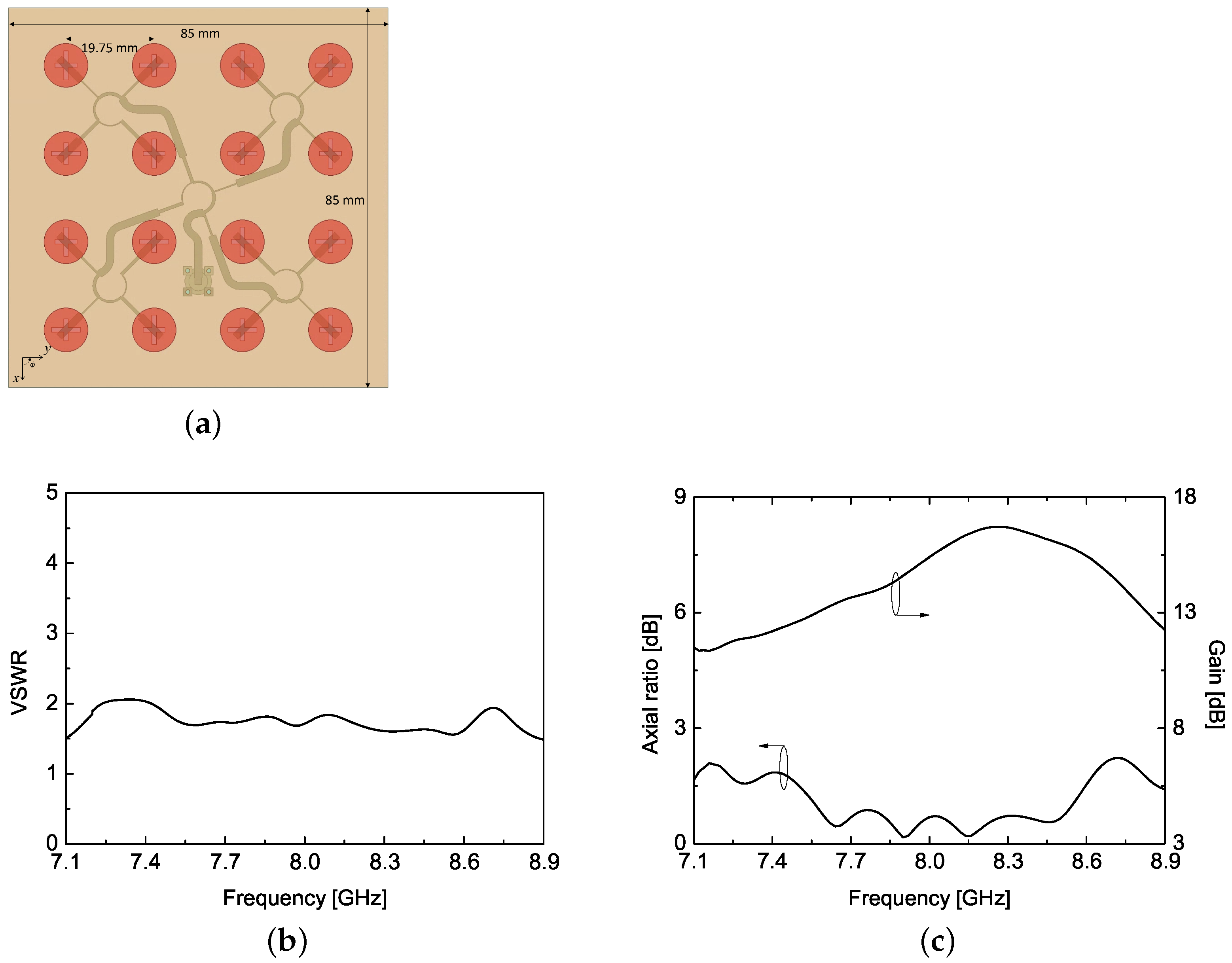
The microstrip transmission line structure forms the feed network designed to realize the CP characteristics. The proposed CP antenna design adopts the sequential rotation of the unit radiating element, as described in the above subsection, and to support this rotation, the feed network must provide an appropriate phase offset to each element. Moreover, the serial feed line structure ensures equal power distribution to the radiating units.
In general, the sequential rotation of m-radiating elements to achieve circular polarization characteristics requires both a physical rotation, ϕ p m , and an electrical rotation by changing the input phase, ϕ e m . Both angles, when the radiating element is operating in the fundamental mode, can be determined as follows [17],
ϕ e m = ϕ p m = ( m 1 ) p π M , 1 m M
where p is an integer and M is the total number of radiating elements. In this research, we assume that p and M are 2 and 4, respectively, so that four radiating units are uniformly placed in the direction of the azimuth angle, ϕ , and each element is fed with 90 ° different input phases compared to the neighboring element. In order to provide the required input phase value to each radiating element with an equally divided power, a 1:4 power divider is designed; its configuration is shown in Figure 3a. The microstrip input port, with a 50 Ω impedance, is designated as port 1, and the port numbering increases in a counterclockwise direction. The power divider is also designed to deliver optimal performance at 8.2 GHz, maintaining an equal power division ratio with a 90 ° phase difference between the output ports. Figure 3b shows that one-quarter of the input power is equally transmitted to each output from an input.
Figure 3. (a) Configuration of a 1:4 power divider design for a sequentially rotated feed network, (b) simulated S-parameter magnitude response, and (c) simulated S-parameter phase response.
Electronics 13 02076 g003
It is important to note that all microstrip line sections are designed to have one-quarter of the guided wavelength of the center frequency, with the impedance values listed in Table 1, resulting in the 90 ° phase shift relative to the neighboring output port (from port 2 to port 5), as shown in Figure 3c. The impedance values listed in Table 1 are obtained using the iterated simulated annealing technique, taking into account the fabrication limits of the 30 mil thick RO4350 substrate.

2.3. Array Design

In this subsection, based on the designs related to the radiating element and power divider shown in the above subsections, we complete the array antenna design and provide the simulation results of the proposed CP antenna.
To properly feed the 16 radiating elements that form a 4 × 4 array, the power divider shown in Figure 3a is extended to have 16 output ports. This could be accomplished with ease by connecting four identical dividers to the output port of a 1:4 power divider, taking into account the electrical length of the additional 50 Ω lines between the dividers, since the feed network was designed for a 2 × 2 subarray. For further clarification, the electric field distributions at the center frequency for the different input signal phases at port 1 are shown in Figure 4. The electric field distribution at the end of a subarray can be simply represented by the black dotted lines. When the input phase changes to 90 ° , the electric field distribution at the end of the subarray can be seen rotating in a counterclockwise direction, and the same distribution is observed in the neighboring subarray, which is sequentially rotated by ϕ p m = 90 ° . As a result, the proposed CP antenna is designed with four 2 × 2 subarrays, each having the same polarization characteristic, to achieve right-handed CP, and the sequentially rotated serial feed network is employed to construct the proposed array antenna.
Figure 5 presents the configuration of the proposed CP 4 × 4 array antenna, its simulated voltage standing wave ratio (VSWR), AR, and total antenna gain. The simulation results show that the proposed antenna has a wider bandwidth than 1.5 GHz for a 2:1 VSWR and a 3 dB axial ratio bandwidth, and its peak gain is greater than 15 dB. For more detailed information at the center frequency of 8.2 GHz, the proposed antenna achieves a VSWR of 1.69, an AR of 0.40, and a peak gain of 16.61 dB. The radiation pattern of the proposed CP antenna is also simulated and plotted at the selected frequency points of 7.6 GHz, 7.9 GHz, 8.2 GHz, and 8.7 GHz, as shown in Figure 6. These frequencies correspond to the operating frequency span that satisfies a 10 dB lower sidelobe level than boresight. The half-power beamwidth varies from 22 ° to 26 ° over the operating frequency span. More details on the capabilities of the proposed CP antenna without sidelobe constraints are provided in the measurement section.

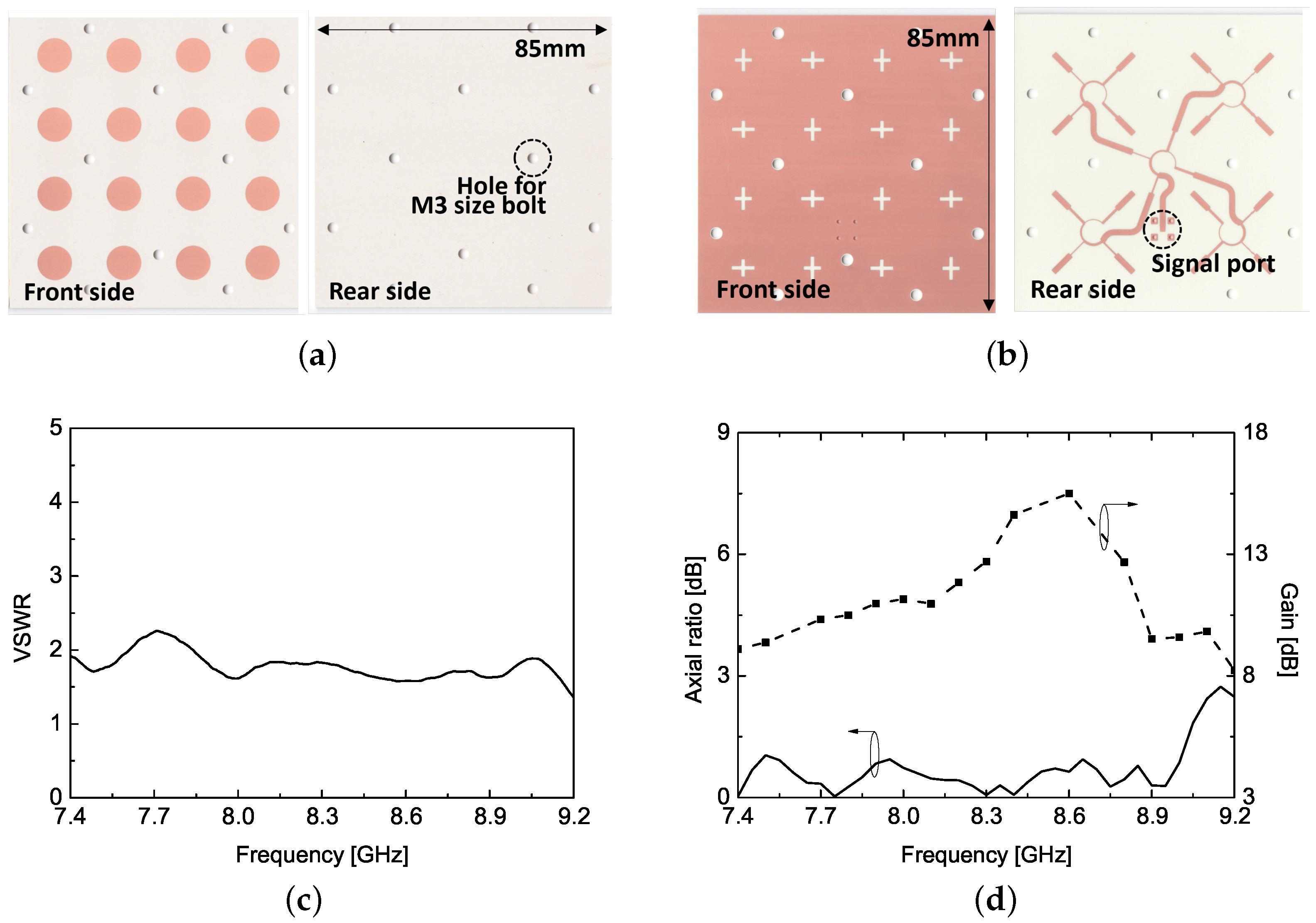
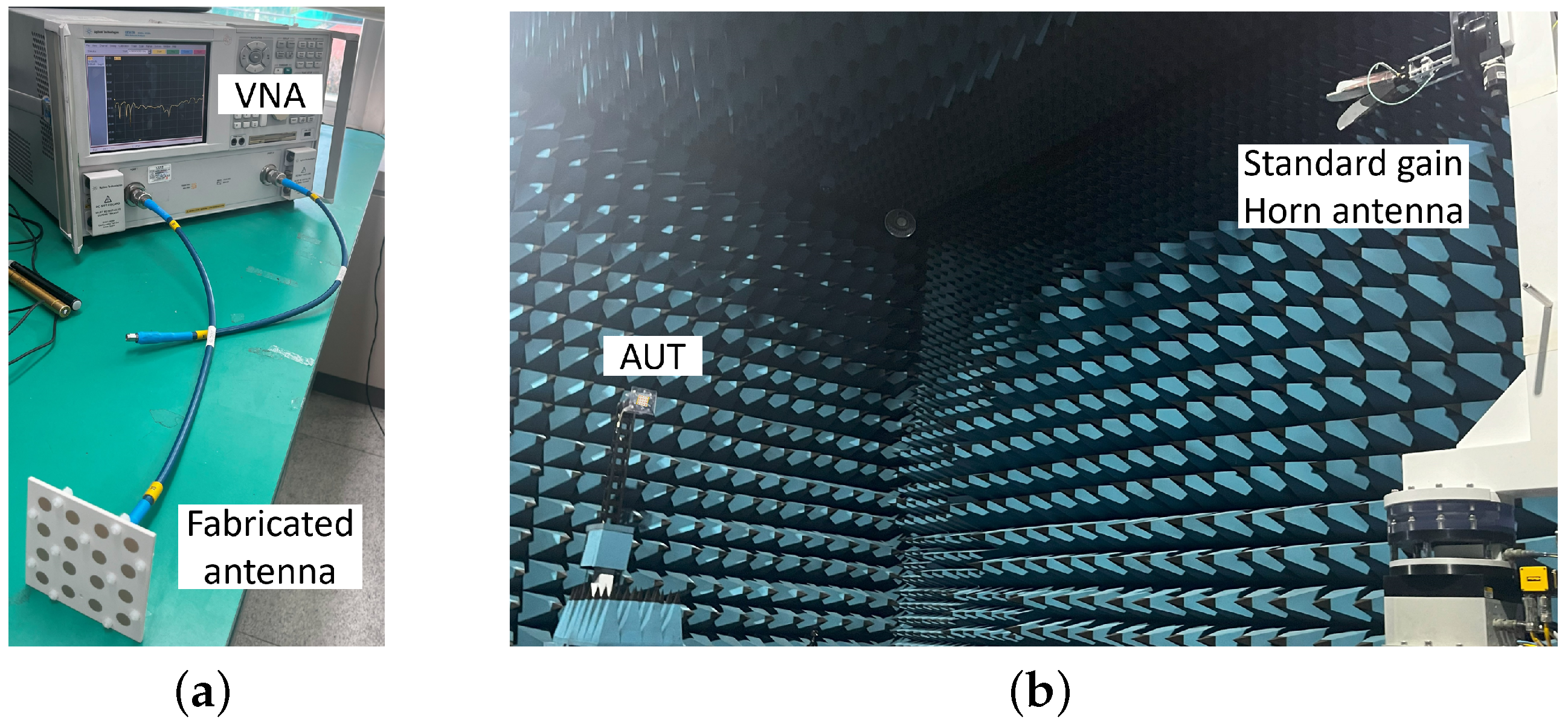
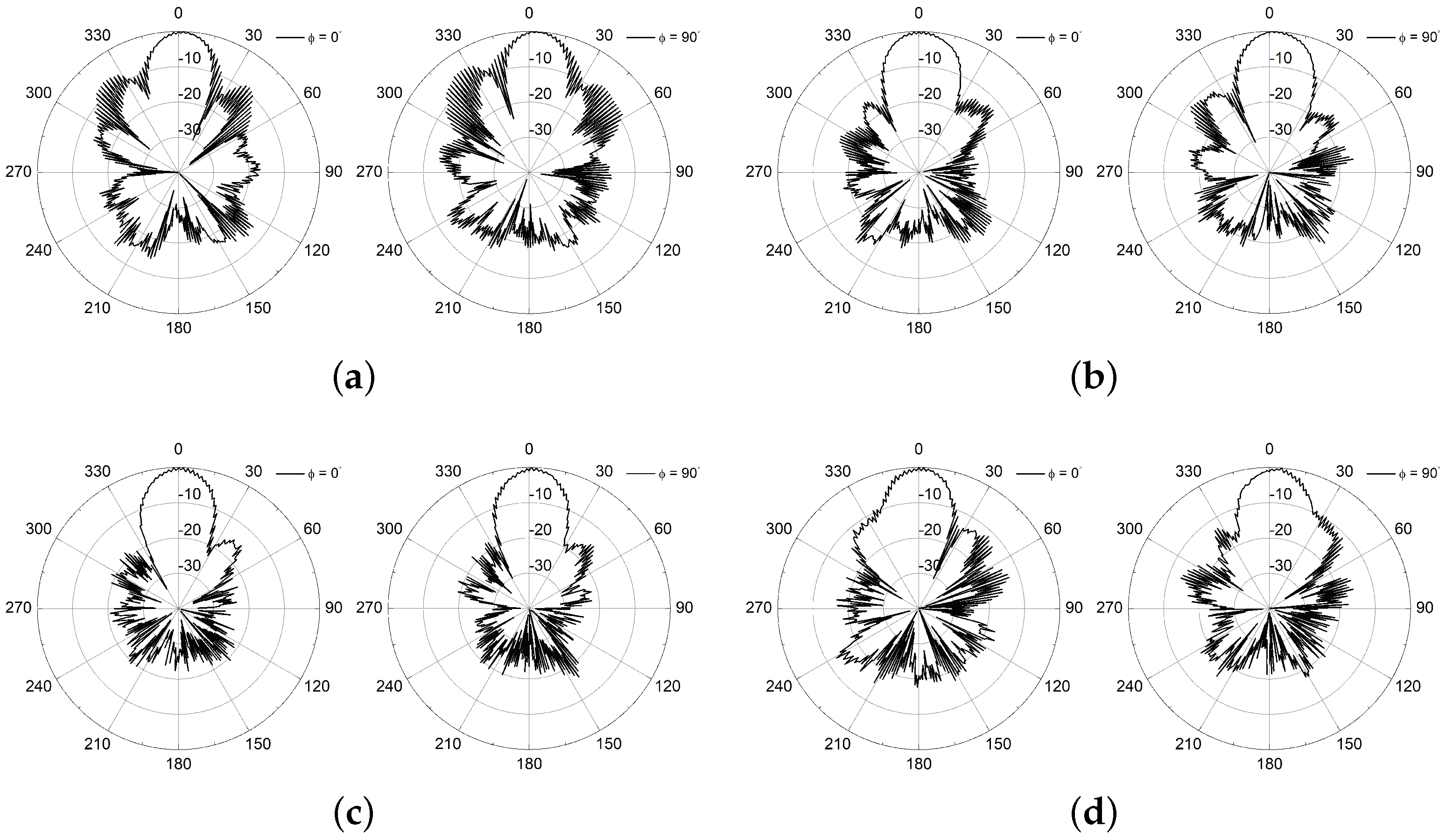
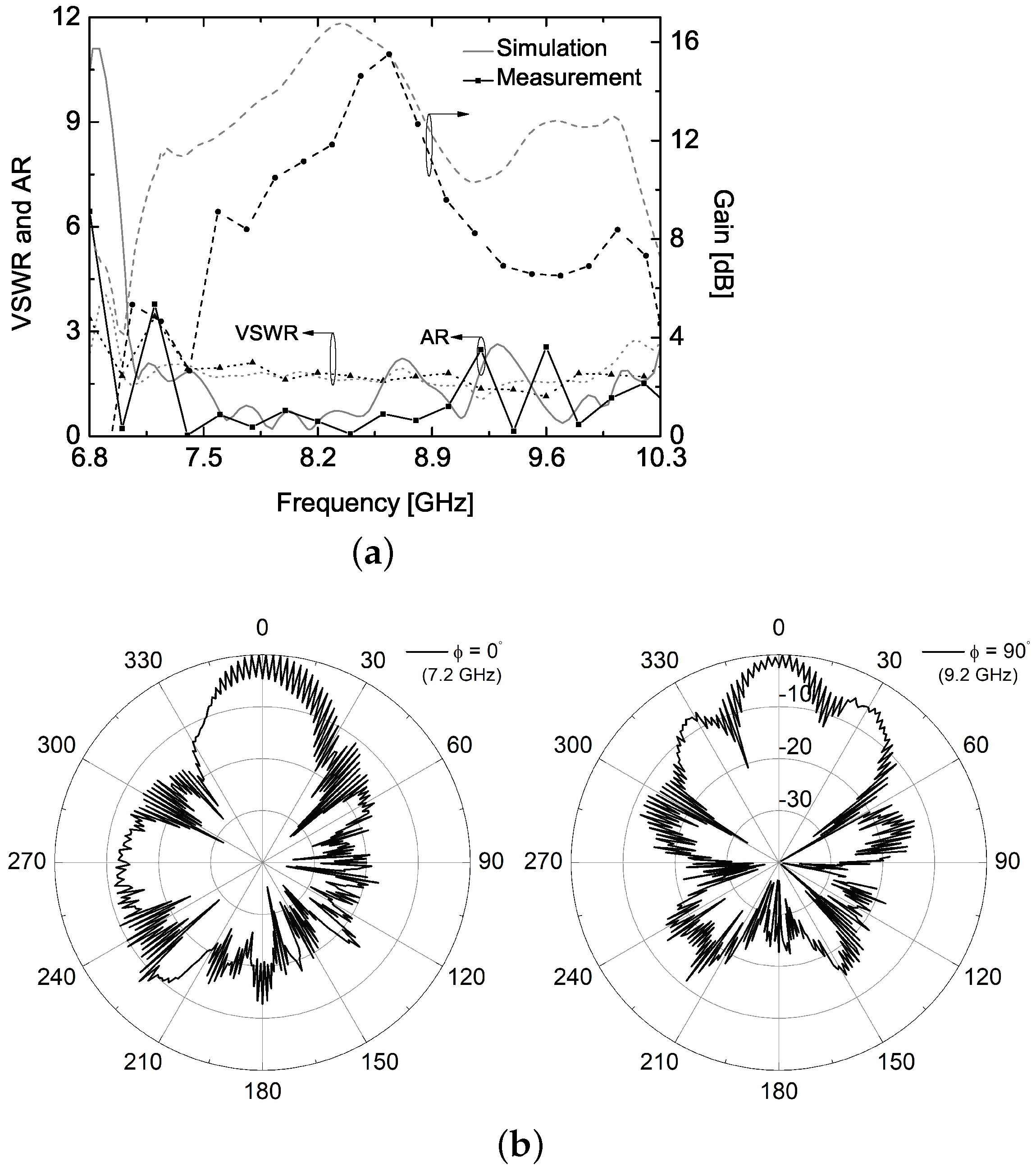
3. Fabrication and Measurement

The proposed CP antenna is fabricated and measured to verify the design theory. As mentioned in the unit radiating element design, the 60 mil and 30 mil thick substrates are used for the 4 × 4 radiating elements and feed network, respectively. Photographs of the fabricated circuits are shown in Figure 7a,b. The rear side of RO3003 is completely etched out because the front side of RO4350, which contains the coupling slots between the radiating elements and the feed network, can provide the electrical ground. Two substrates are mechanically laminated and aligned together using M3-sized plastic bolts and nuts through holes in both substrates. A surface-mounted device (SMD) type SMA connector from Molex (Lisle, IL, USA), which can be used up to 18 GHz, is soldered and used for measuring. The signal port is also grounded through via holes.
The impedance matching characteristic of the proposed antenna is measured using Keysight PNA E8363B (Keysight, Santa Rosa, CA, USA), and the measurement results and setup are presented in Figure 7c and Figure 8a, respectively. The fabricated antenna exhibits a 1.82:1 VSWR at the designed center frequency of 8.2 GHz. Due to the sequentially rotated series feed network, it maintains better than 2:1 VSWR characteristics over a wide frequency range of interest, except for the 200 MHz frequency band centered at 7.7 GHz, which has a maximum VSWR of 2.25:1. The proposed CP antenna structure employs the sequential rotation of radiating elements and also achieves broad impedance and AR bandwidth since off-frequency reflections at the feed point tend to be canceled out. Compared with the simulation results shown in Figure 5b, the measured results show a 4.4% frequency shift toward the upper band. This deviation may be attributed to the difference in the relative dielectric constants between the simulation and fabrication, although the general characteristics of the antenna have been maintained in the measurement results. To verify the CP radiation characteristic of the proposed antenna, the axial ratio, antenna gain, and radiation patterns are measured in an anechoic chamber, as shown in Figure 8b. The fabricated antenna shows an 11.84 dB total gain with an axial ratio of 0.42 dB at the center frequency, and it shows a maximum gain value of 15.50 dB at 8.60 GHz, which is a 1.2 dB deviation compared to the simulation results. As expected, the feed network enables the devised antenna to exhibit excellent AR characteristics over a wide frequency range, as shown in Figure 7d. It is possible that the measured antenna gain and AR may be degraded when applied to applications involving an outdoor repeater or micro-satellite. However, the proposed antenna is capable of transmitting and receiving circularly polarized electromagnetic waves, as evidenced by the measured results.
The measured radiation patterns are presented in Figure 9. To assess the CP radiation characteristic of the proposed antenna using a linearly polarized standard horn, the radiation patterns of the major and minor axes of the AUT are measured, respectively, and the axial ratio pattern (referred to as the spinning radiation pattern) is mathematically obtained at each frequency. Figure 9 shows the measured radiation patterns at 7.8 GHz, 8.2 GHz, 8.6 GHz, and 9.0 GHz, and these points are selected when the proposed CP antenna has a 10 dB-smaller sidelobe level, which is the same as in the simulation results. It can be observed that a ripple is present at the boresight θ = 0 ° with a magnitude of less than 1 dB. This indicates that the fabricated antenna exhibits excellent AR characteristics at those frequency points. It should be noted that the experimental results show some frequency shift, but the proposed antenna has both a similar CP operating bandwidth and an excellent radiation characteristic at the center frequency of 8.2 GHz and at the frequency point where the proposed antenna has the maximum gain value. In addition, the fabricated antenna has about a 21 ° half-power beamwidth, AR values less than 1 dB, and antenna gain greater than 9.5 dB.
Figure 10 shows both simulation and measurement results with a wide frequency span from 7.0 GHz to 10.0 GHz. If one is looking for a CP antenna that can provide the 3 dB AR bandwidth greater than 30% without any limitation in terms of the side lobe level or gain, the proposed CP antenna can satisfy the bandwidth requirement. However, in this research, we limit the side lobe level to 10 dB lower than the boresight direction, and we provide detailed measurement results over a narrower frequency span as shown in Figure 7 and Figure 9. For example, the radiation patterns at frequencies of 7.2 GHz and 9.2 GHz are shown in Figure 10b, and these patterns have undesirable AR or side love levels. On the other hand, if the radiating elements are modified to have a reconfigurable characteristic that maintains the electrical distance between them, the revised CP antenna could achieve an extended operating frequency band with improved radiation performance, but this is beyond the scope of this manuscript.
Table 2 presents a comparative analysis of the proposed CP antenna with other ones exhibiting comparable radiation characteristics but differing in their design techniques. The CP antennas are categorized based on their impedance and AR bandwidth, peak gain, type of radiating unit, presence of a reflector, and size measured in electrical length.

4. Conclusions

The circularly polarized antenna operating in the X-band is designed and validated through fabrication. The proposed CP antenna has a simple structure without a reflector, yet it achieves a peak gain greater than 16 dB at the center frequency. The sequentially rotated serial feed network is designed for 4 × 4 radiating elements with the proper phase response to realize the circular polarization characteristic. The precisely designed feed line enables the proposed antenna to have broadband characteristics in terms of both impedance matching and axial ratio performance. The proposed antenna is fabricated based on the reliable fabrication process and can be a candidate for the transceiver component of micro-satellites or CubeSat applications.

Author Contributions

Conceptualization, T.-H.L.; software, T.-H.L.; validation, T.-H.L.; writing—original draft preparation, T.-H.L. writing—review and editing, T.-H.L., J.J. and S.P.; supervision, J.J. and S.P.; funding acquisition, S.P. All authors have read and agreed to the published version of the manuscript.

Funding

This research was supported by the research fund of Hanbat National University in 2023 and this work was also supported by Korea Research Institute for defense Technology planning and advancement (KRIT) grant funded by the Korea government (Defense Acquisition Program Administration, 21-106-A00-007, Space-Layer Intelligent Communication Network Laboratory, 2022).

Data Availability Statement

The data that support the finding of this study are available within the article.

Conflicts of Interest

The authors declare no conflicts of interest.

References

  1. Khan, I.; Wu, Q.; Ullah, I.; Rahman, S.U.; Ullah, H.; Zhang, K. Designed circularly polarized two-port microstrip MIMO antenna for WLAN applications. Appl. Sci. 2022, 12, 1068. [Google Scholar] [CrossRef]
  2. Fatima, I.; Ahmad, A.; Ali, S.; Ali, M.; Baig, M.I. Triple-band circularly polarized antenna for WLAN/Wi-Fi/Bluetooth/WiMAX applications. Prog. Electromagn. Res. C 2021, 109, 65–75. [Google Scholar] [CrossRef]
  3. Chen, H.-M.; Chiu, K.-Y.; Lin, Y.-F.; Wen, H.-N.; Jan, J.Y.; Yang, C.F. Single-layer circularly polarized patch antenna for RFID reader application. In Proceedings of the Antennas and Propagation Society International Symposium, North Charleston, SC, USA, 1 June 2009. [Google Scholar]
  4. Budroweit, J.; Eichstaedt, F.; Stehle, F. Design and characterization of a multi-channel ADS-B antenna for small satellites. In Proceedings of the Space Hardware and Radio Conference, San Antonio, TX, USA, 21 January 2024. [Google Scholar]
  5. Liu, X.; Wang, H.; Yang, X.; Wang, J. Quad-band circularly polarized antenna for GNSS, 5G, and WiFi-6E applications. Electronics 2022, 11, 1133. [Google Scholar] [CrossRef]
  6. Zheng, B.; Li, N.; Li, X.; Rao, X.; Shan, Y. Miniaturized wideband CP antenna using hybrid embedded metasurface structure. IEEE Access 2022, 10, 120056–120062. [Google Scholar] [CrossRef]
  7. Li, J.-F.; Xu, T.; Wu, D.-L.; Hu, Z.-X.; Zhang, G.; Tian, X.-X.; Ye, L.-H. A dual-circularly polarized wideband dipole antenna with stable axial-ratio and half-power beamwidth. IEEE Antennas Wireless Propag. Lett. 2023, 22, 1701–1705. [Google Scholar] [CrossRef]
  8. Sun, M.; Zhang, Z.; Zhang, F.; Chen, A. L/S multiband frequency-reconfigurable antenna for satellite applications. IEEE Antennas Wireless Propag. Lett. 2019, 18, 2617–2621. [Google Scholar] [CrossRef]
  9. Rezaeieh, S.A.; Abbosh, A.; Antoniades, M.A. Compact CPW-fed planar monopole antenna with wide circularly polarization bandwidth. IEEE Antennas Wireless Propag. Lett. 2013, 12, 1295–1298. [Google Scholar] [CrossRef]
  10. Sze, J.-Y.; Pan, S.-P. Design of CPW-fed circularly polarized slot antenna with a miniature configuration. IEEE Antennas Wireless Propag. Lett. 2011, 10, 1465–1468. [Google Scholar] [CrossRef]
  11. Wang, H.; Byun, G.; Park, Y.B.; Park, I. Circularly polarized wideband unipolar crossed-dipole antenna with folded striplines and rectangular stubs. IEEE Access 2023, 11, 63252–63260. [Google Scholar] [CrossRef]
  12. Biswas, S. Wideband and dual-polarized cross dipole antenna design using substrate-integrated coax. IEEE Open J. Antennas Propag. 2023, 4, 361–372. [Google Scholar] [CrossRef]
  13. Yang, Z.; Bao, J.; Li, W.; Liu, B.; Wang, H.; Kang, L.; Shi, X.-W. Broadband circularly polarized antenna with non-planar reflector. IEEE Access 2020, 8, 164407–164413. [Google Scholar] [CrossRef]
  14. Baik, J.-W.; Lee, K.-J.; Yoon, W.-S.; Lee, T.-H.; Kim, Y.-S. Circularly polarised printed crossed dipole antennas with broadband axial ratio. Electron. Lett. 2008, 44, 785–786. [Google Scholar] [CrossRef]
  15. Baik, J.-W.; Lee, T.-H.; Pyo, S.; Han, S.-M.; Jeong, J.; Kim, Y.-S. Broadband circularly polarized crossed dipole with parasitic loop resonators and its arrays. IEEE Trans. Antennas Propag. 2011, 59, 80–88. [Google Scholar] [CrossRef]
  16. Xu, R.; Shen, Z.; Gao, S.S. Compact-size ultra-wideband circularly polarized antenna with stable gain and radiation pattern. IEEE Trans. Antennas Propag. 2022, 70, 943–952. [Google Scholar] [CrossRef]
  17. Hall, P.S.; Dahele, J.S.; James, J.R. Design principle of sequentially fed, wide bandwidth, circularly polarised microstrip antennas. IET Proc. 1989, 136, 381–389. [Google Scholar] [CrossRef]
  18. Hall, P.S. Application of sequential feeding to wide bandwidth circularly polarised microstrip patch arrays. IET Proc. 1989, 136, 390–398. [Google Scholar] [CrossRef]
  19. Evans, H.; Gale, P.; Aljibouri, B.; Lim, E.G.; Korolkeiwicz, E.; Sambell, A. Application of simulated annealing to design of serial feed sequentially rotated 2 × 2 antenna array. Electron. Lett. 2000, 36, 1987–1988. [Google Scholar] [CrossRef]
  20. Evans, H.; Gale, P.; Sambell, A. Performance of 4 × 4 sequentially rotated patch antenna array using series feed. Electron. Lett. 2003, 39, 493–494. [Google Scholar] [CrossRef]
  21. Abulgasem, S.; Tubbal, F.; Raad, R.; Theoharis, P.I.; Lu, S.; Iranmanesh, S. Antenna designs for cubesats: A review. IEEE Access 2021, 9, 45289–45324. [Google Scholar] [CrossRef]
  22. Ma, B.; Lu, F.; Zhi, G.; Xue, X.; Zhao, X.; Ma, C.; Fan, Y.; Yang, M. Development of an X-Band Reflectarray Antenna for Satellite Communications. Sci. Rep. 2021, 11, 6530. [Google Scholar] [CrossRef]
  23. Huang, C.-Y.; Wu, J.-Y.; Wong, K.-L. Cross-slot-coupled microstrip antenna and dielectric resonator antenna for circular polarization. IEEE Trans. Antennas Propag. 1999, 47, 605–609. [Google Scholar] [CrossRef]
Figure 1. (a) Top and side views of a unit radiating patch of the proposed CP antenna, (b) simulated return loss, and (c) simulated AR and gain. ( l m = 2.15, l s 1 = 4.9, l s 2 = 6.5, w s = 1, r = 4.9, all in millimeter).
Electronics 13 02076 g001
Figure 2. Parameter studies on the unit radiating patch: (a) patch’s radius, r, variation, (b) microstrip line length, l m , (c) slot length, l s 1 , and (d) slot length, l s 2 .
Electronics 13 02076 g002
Figure 4. Electric field distributions for different input signal phases at 8.2 GHz.
Electronics 13 02076 g004
Figure 5. (a) Proposed circularly polarization 4 × 4 array antenna, (b) simulated VSWR, and (c) simulated AR and gain.
Electronics 13 02076 g005
Figure 6. Simulated radiation patterns of the proposed CP antenna at various frequencies: (a) 7.6 GHz, (b) 7.9 GHz, (c) 8.2 GHz, and (d) 8.7 GHz.
Electronics 13 02076 g006
Figure 7. Photograph of the fabricated antenna and its measured results: (a) front and rear sides of RO3003, (b) front and rear sides of RO4350, (c) measured VSWR, and (d) measured AR (solid line) and gain (dashed line).
Electronics 13 02076 g007
Figure 8. Photographs of measurement setup: (a) VSWR and (b) radiation pattern in anechoic chamber.
Electronics 13 02076 g008
Figure 9. Measured radiation patterns of the proposed antenna at different frequencies: (a) 7.8 GHz, (b) 8.2 GHz, (c) 8.6 GHz, and (d) 9.0 GHz.
Electronics 13 02076 g009
Figure 10. Experimental results of the proposed CP antenna with a wide frequency span: (a) VSWR, AR, and gain characteristic and (b) radiation patterns at 7.2 GHz and 9.2 GHz.
Electronics 13 02076 g010
Table 1. Impedance values for the 1:4 power divider (the unit is Ω ).
Z 0 Z 1 Z 2 Z 3 Z 4 Z 5 Z 6 Z 7
5010080120968012880
Table 2. Comparison of antenna characteristics.
Impedance BW [%]3dB AR BW [%]Measured Peak Gain [dB]Radiating Unit TypeReflectorSize [ λ 3 ]
[11]55.2653.52.1crossed dipoleX0.57 × 0.57 × 0.0027
[13]132.1128.69.5crossed dipoleO0.27 × 0.27 × 0.12
[14]38.239.213.0crossed dipoleO1.61 × 1.61 × 0.25
[15]41.256.214.2crossed dipoleO1.61 × 1.61 × 0.25
[16]120.9133.311.2microstrip patchO0.89 × 0.89 × 0.09
This work37.244.516.2microstrip patchX2.32 × 2.32 × 0.062
Disclaimer/Publisher’s Note: The statements, opinions and data contained in all publications are solely those of the individual author(s) and contributor(s) and not of MDPI and/or the editor(s). MDPI and/or the editor(s) disclaim responsibility for any injury to people or property resulting from any ideas, methods, instructions or products referred to in the content.

