Abstract
Among the conventional inks used for inkjet printing, metals, oxides, or polymers have been deposited in order to form functional coatings. Gold is one of the most used metals for electrode fabrication in the gas sensor field due to its inert behavior when exposed to reactive gases and conductive properties. However, only a few commercial gold inks are commercially available, and the combination of excessive price, a high minimum purchase quantity, and an unknown composition renders the actual products unappealing. To meet these shortcomings, gold inks were formulated with different solvents in order to reach sufficient properties for the inkjet printing process, such as surface tension and viscosity. On the one hand, gold ink was developed using a gold nanoparticle (AuNP) solution as the metal. This ink was optimized from nanoparticle synthesis, with the ink formulation obtaining a 32 mN·m−1 surface tension and 11.2 mPa·s viscosity in order to be inkjet-printed onto polyimide foil. On the other hand, a particle-free ink, called a precursor based of ink, was also developed. In this case, ink was made by solubilizing gold salt in aqueous medium in order to reach jettable properties. Surface tension was measured at 32 mN·m−1 while viscosity was 14.0 mPa·s. Then, printing and deposition parameters were optimized in order to obtain a highly conductive gold coating. The measured resistivity was 2 × 10⁻⁷ Ω·m which is close to the bulk gold conductive value. These coatings could be used for the fabrication of various devices in different working fields.
1. Introduction
Gas sensors have been widely studied in many research areas such as automotive [1], environmental [2], indoor air monitoring [3], or industrial facilities. Depending on the sensor application and the targeted gas, optical [4], FET [5], piezoelectric [6], electrochemical [7], or metal oxide sensors [8] have been used. The metal oxide sensor provides a promising way of moving forward in the sensor field due to its high sensibility, stability, and low fabrication cost [9]. However, a well-known disadvantage of this type of sensor is the lack of selectivity when exposed to multiple gas [10]. These sensors are composed mainly of two elements, a patterned two-separated electrode system made of conductive metal such as Au, Pt, or Ag, and a sensing layer made of semi-conductive metal oxide bridging the electrode system [11]. A form of electrical resistance like a heater can be placed on the opposite face of the sensing materials [12]. The most common sensing material for semi-conductive metal oxide gas sensors is SnO2. These sensors are generally deposited on rigid inorganic substrates like alumina [13], or silicon wafers [14]. In the recent development of sensors, to reduce costs and to expand the application of sensors, flexible substrates have been introduced to replace rigid substrates [15]. New substrates such as plastics, papers, and textiles are now commonly used for producing several types of sensors for different applications like wearable electronics for health monitoring [16] or electronics for gas exposition measurement [17]. Nevertheless, despite the advantages of flexible substrates, there is an intrinsic limitation due to the use of polymeric or paper-based substrates to provide the thermal resistance. The degradation temperature of paper is around 100–120 °C [18]. For polymeric substrates, thermal degradation generally occurs below 300 °C for most polymer foils that are commercially available [19]. For polyimide (PI), the data show that the foil is not degraded below 400 °C, which is a very high thermal degradation temperature for polymers. In comparison to the classical rigid substrates for electronics, silicon can tolerate 1410 °C before melting and the Al2O3 substrate melting point is 2072 °C [20]. The thermal resistance of flexible substrate is low in comparison, which will have the consequence of ruling out certain processes like severe annealing or sintering of particles at high temperatures. Low boiling-point solvents are required to evaporate quickly at low temperatures to avoid any substrate degradation caused by heat.
Concerning deposition methods, numerous methods have been developed such as spin coating, spray coating, screen-printing, flexography printing, and inkjet printing. Depending on the application and the final coating properties, a different deposition process should be preferred. All these different techniques have their pros and cons. For example, screen-printing allows the mass production of coatings with low wastage of materials but involves the employment of a non-volatile and thick paste [21]. Moreover, the quantity and morphology of the deposited material are not optimized in comparison to other methods [22]. For inkjet printing, a relatively fluid ink is needed with a low viscosity to obtain printed patterns. It leads to high-resolution printing with easily tunable patterns with no wasted ink. This printing technique could also be used at room temperature. This is why it is particularly interesting for printing onto plastic foil. Nevertheless, inkjet printing is relatively slow in comparison to other deposition techniques, which limits its use for industrial applications. Inkjet printing has been widely described in the literature [23,24]. Two deposition mechanisms are mainly used, continuous and drop-on-demand inkjet printing [25]. Continuous inkjet printing is based on a continuous ejection of fluid through the nozzle. To correctly print the pattern, a gutter is electronically controlled to interrupt the inkjet flow onto the non-deposition area. Concerning drop-on-demand (DOD) inkjet printing, the droplet is only deposited on the specific area of the substrate, which means droplets are ejected only when it is necessary. The drop-on-demand inkjet printing mechanism is triggered by a pressure increase. This pressure change is generated by two main phenomena, ink phase changes due to temperature variations [23] or the piezoelectric actuator [26]. As previously mentioned, inkjet printing inks are very different from the ones used for other deposition methods. The major properties of this type of ink are viscosity and surface tension at the temperature fixed at the nozzle during the jetting process [27]. These inks must have a low viscosity of approximately 10 mPa·s, close to the water value, depending on the system used for fluid ejection, and a low surface tension [28] of around 30 mN·m−1. The solid particles composing the ink should be less than 1/100th of the nozzle to avoid clogging. Metallic Ag, Au, Cu, and Pt inks have been developed for inkjet printing deposition for electronic devices. Silver ink is a popular metal ink and many providers produce this type of ink. Silver is mostly used for electronic device fabrication [29] due to its high conductivity and its low price compared to other metals such as gold and platinum [30]. However, even if it is the most conductive metal, silver is also a reactive material that can be oxidized while being exposed to reactive conditions. For the semi-conductive metal-oxide gas sensor fabrication, severe conditions are used to activate the semiconductor element, and reducing and oxidizing gas exposition could deteriorate the sensor materials [31]. Gold is a stable metal compared to silver and copper. Furthermore, gold is also catalytically inactive unlike platinum electrodes that are well known for reacting with gaseous species. This is why gold is mostly used for gas sensor electrode fabrication as it is the most stable and conductive metal that can withstand MOx sensor working conditions [32].
Several commercially available gold inks for inkjet printing are listed in Table 1. Another concern when utilizing commercial inks, besides their price, is the reproducibility issue between batches, which can significantly affect the research and sensor fabrication. Furthermore, the relatively short lifespan and stability of these inks have to be associated with the minimum purchasable quantity and the material waste it costs. Finally, additives used for commercial ink fabrication are unknown most of the time, meaning they can be polluting or interfering with required properties. These impurities could modify the final sensor device response due to chemical reactions. Table 1 highlights that the resistivity obtained with commercial inks is higher by at least a factor of 5 to 10 than the bulk gold which is 2.4 × 10⁻⁸ Ω·m that could be caused by inhomogeneous coverage, porosity, or impurities.

Table 1.
Example of commercial gold inks available for inkjet.
Academic research groups have also developed gold inks for different applications but there are some limitations. The most important one is the use of organic solvents, which are undesirable in this study for environmental reasons. As an example, the synthesis based on the Brust method led to the gold nanoparticle ink being obtained in toluene-based solvent [37] and working with a hazardous reactive such as NaBH4. The transition from organic solvent-based nanoparticles to a water-based medium is possible but not very easy and involves several difficult steps. As an example, Mekhmouken et al. [38] described a new method of obtaining gold nanoparticles in aqueous media by modifying the thiol group to make it hydrophilic which led to stabilizing the gold nanoparticles in water. Nevertheless, the time-consuming synthesis steps and the high cost of this PEG thiol are limitations. Among the different gold synthesis methods, the synthesis of AuNPs has focused the attention of researchers. AuNP ink could be convenient for printing and can be processed at low temperatures, which is interesting for deposition on a flexible substrate. The main issue for this type of ink is not to clog the small nozzle because of the agglomeration of particles that could form larger clusters. A decent particle-loading in the ink could be hard to reach while keeping particle stability. Particle-free inks have also been developed to avoid these clogging issues [39].
In this study, an experimental means is proposed of obtaining easy-to-prepare, stable, and tunable gold inks for inkjet printing of high-quality patterns onto plastic foils for electronic applications. The purpose is to obtain gold tracks and electrodes for the fabrication of a metal oxide gas sensor. Aqueous medium gold nanoparticles and particle-free ink will be developed. The optimization of both of these inks, including the ink formulation, deposition of the ink, thermal treatment parameters, and characterization of the printed pattern obtained, are further developed.
2. Materials and Methods
2.1. Materials
All the chemicals used in this study were provided by Sigma Aldrich and were used as received: tannic acid (TA), sodium citrate (SC), chloroauric acid (HAuCl4), propan-2-ol, glycerol, and ethylene glycol. The development of two inks is presented through this article, one based on gold nanoparticles and the other one directly obtained with an HAuCl4 precursor.
2.2. Gold Nanoparticle (AuNP) Synthesis and Characterization
The AuNP synthesis method proposed here is an adaptation of the well-known Turkevich method proposed by Piella et al. [40]. This synthesis was optimized in order to obtain the most concentrated AuNP solutions for our application purpose.
Briefly, a reducing solution of 50 mL containing a mixture of 200 mmol·L−1 of sodium citrate (SC) and 0.06 mmol·L−1 of tannic acid (TA) was heated at 70 °C. The pH of this solution was slightly above 6.5. When reaching 70 °C, the chloroauric acid solution in water was quickly added to the reducing solution under vigorous stirring. The gold solution quantity added to the reducing solution was varied in order to obtain, after synthesis, different gold concentration solutions from 0.25 mmol·L−1 to 3.3 mmol·L−1. After heating for 5 more minutes, the reaction was completed. A quite dark red solution of gold nanoparticles was then observed.
The obtained solutions were then characterized. Dynamic light scattering (DLS) was used with the Malvern Zetasizer device to study the mean diameter of nanoparticles in aqueous suspension. AuNP solutions were characterized with a UV–visible spectrometer (CARY 300 SCAN, Agilent Technologies, Santa Clara, CA, USA) to control the evolution of the nanoparticle suspension through time. Transmitting electron microscopy analysis (TEM; Philips CM200, Philips, Amsterdam, The Netherlands) was performed to measure and analyze the shape and the diameter of the dried nanoparticles deposited onto a copper/carbon grid.
2.3. Inkjet Technique
The printer model used in this study was the Dimatix DMP2850 (FUJIFILM, Santa Clara, CA, USA) printing with DMP 11600 cartridges. According to the jettability window identified by Derby [25], surface tension and viscosity are key parameters for the ink to be correctly jetted through the inkjet printing process. The recommended range parameters provided by Dimatix for their specific inkjet printer and cartridge are presented in Table 2.
Table 2.
Ink properties as advised by Dimatix.
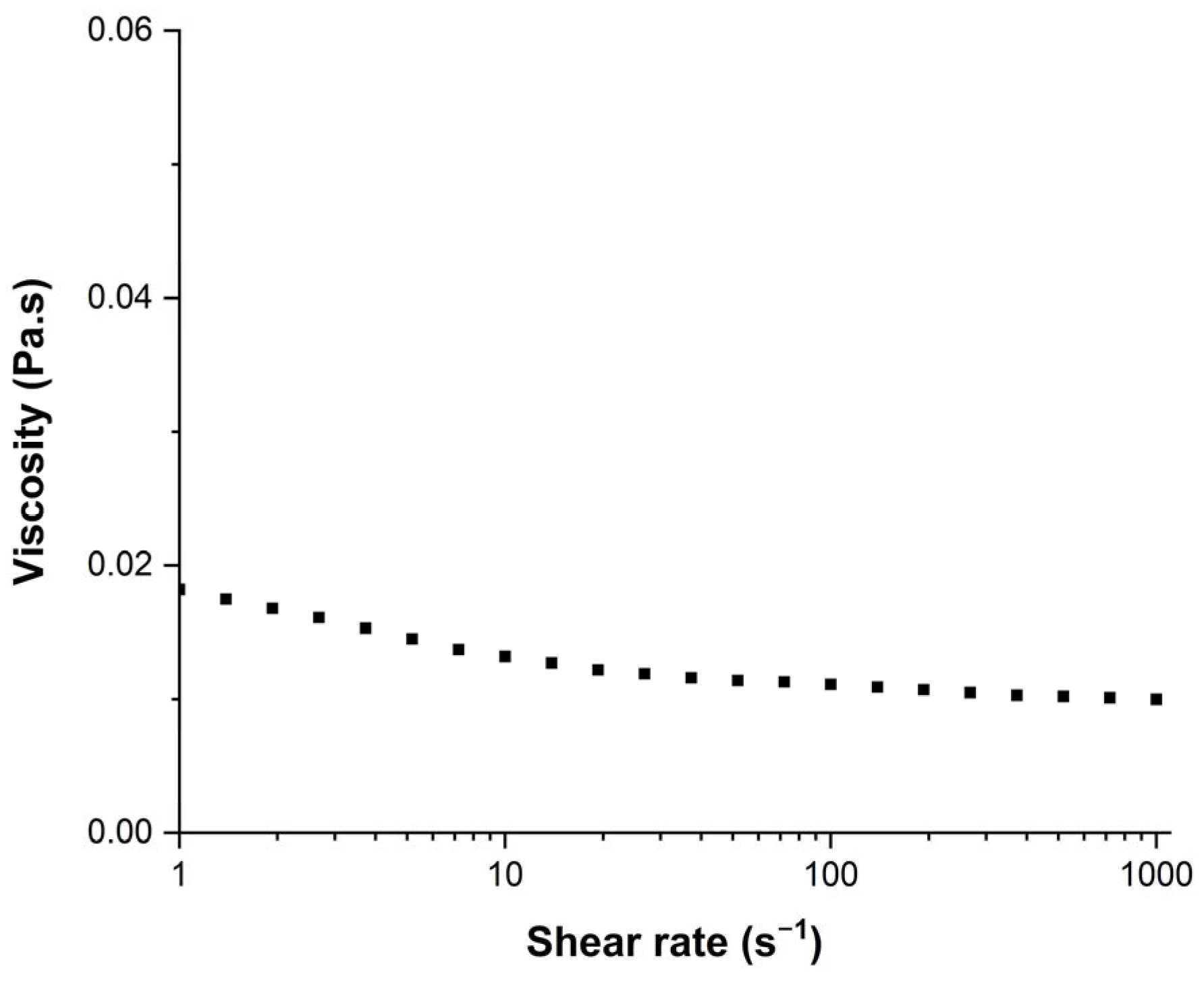
Inks were formulated using different viscosity and surface tension modifiers such as glycerol whose role was to increase the viscosity [41], ethylene glycol equally was used to increase the ink viscosity [42], and propan-2-ol and ethanol which were expected to decrease the surface tension [43]. The surface tension of inks was measured with a manually calibrated Digidrop apparatus using the pendant drop measurement method (Young Laplace model). Viscosity was measured with an MCR302 rheometer provided by Anton-Paar. A cone–plane geometry (known as CP50-2°) with a 50 mm plate diameter and a 2° angle cone was used to determine the viscosity of the inks and solutions. Viscosity measurements were achieved with a shear rate ranging from 1 to 1000 s−1. As presented in Figure 1, for an ink with AuNPs, the fluid showed non-Newtonian properties with a viscosity that decreased as the shear rate increased. The viscosity was significantly decreasing in the range from 1 to 10 s−1, and then slightly decreasing from 10 to 1000 s−1. The viscosity value mentioned in the next sections will be calculated using the average from the 15 points measured between 10 and 1000 s−1.

Figure 1.
Viscosity of the AuNP ink as function of the shear rate applied.
In order to determine the temperature of decomposition of the ink, thermogravimetric (TGA) and calorimetric (DSC) analyses were performed with a METTLER Toledo TGA/DSC 1 STAR system with a 10 °C min−1 ramp and a 600 °C maximum temperature.
Printing parameters were optimized by observing the droplet behavior through the drop-watcher camera until obtaining homogeneous, round, and stable jetting. Firstly, a trapezoidal waveform was used to stimulate the piezoelectric element to increase pressure on the ink tank, which led to the ejection of the droplet through nozzles (Figure 2). Then, the voltage and temperature were modified in order to obtain satisfying jetting properties. The jetting optimal parameters are discussed in the Results section. Optimal settings like frequency of jetting, distance between nozzles and platen or nozzles (Tn), and platen (Tp) temperature were fixed after being determined; these values are 5 kHz, 1 mm, Tn = 35 °C, and Tp = 50 °C, respectively.
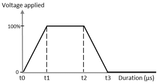
Figure 2.
Example of the piezoelectric waveform applied to the cartridge for inkjet printing process.
2.4. Flexible Substrate
A 50 μm thick polyimide foil was selected as a substrate and was provided by Upilex. Before any gold deposition on the substrate, each foil of the polyimide was washed with de-ionized water and ethanol and then dried with compressed air.
2.5. Thermal Treatment of Deposited Inks
Inkjet-printed coatings were dried in an oven at 110 °C for 15 min. Then, coatings were thermally treated at 350 °C for 2 h with a ramp of 2 °C min−1. Multiple cycles of printing/drying were also investigated.
2.6. Characterizations of Solid Particles and Coatings
Macroscopic images were taken with a fiducial camera mounted on top of the Dimatix DMP2850 printhead. An optical microscope (Olympus BX60M, Evident, Rungis, France) was used to take pictures of the dried gold coatings at different magnifications. In addition, SEM (Zeiss SUPRA 55VP, Zeiss, Oberkochen, Germany) was used to provide images of heat-treated gold coatings. Electrical measurement was carried out using a four-point method to accurately determine the resistivity of gold coatings at room temperature. A cross-section of the coating was inspected with SEM to determine its thickness and thus be able to calculate its resistivity.
3. Results and Discussion
3.1. AuNP Ink Development
Working with NPs should allow the coating to be sintered at a temperature compatible with polyimide support, i.e., below 400 °C. Furthermore, the objective of this study is to work with NPs in solution for the preparation of the ink, for two main raisons: one experimental, in order to prevent agglomeration and the clogging of the nozzles and the other to prevent safety problems using nanoparticles in the laboratory.
3.1.1. AuNP Solutions
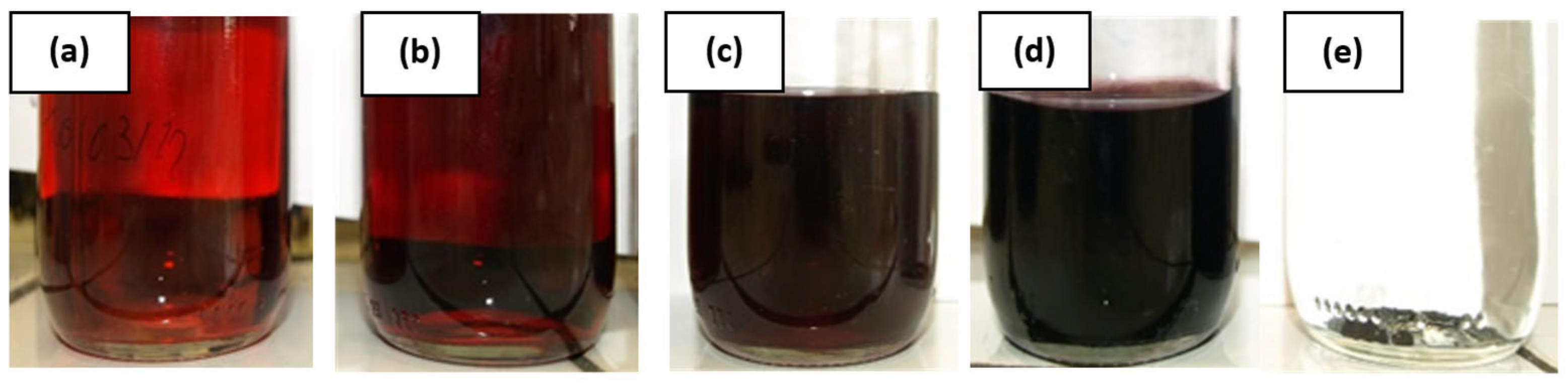
The first less concentrated solution, with an Au concentration of 0.25 mmol·L−1, is based on the description of Piella et al. [40] and is reported in Figure 3a. Then, the concentrations are increased to 0.49, 1.5, 3.3, and 6.4 mmol·L−1 corresponding to Figure 3b–e, respectively. At a concentration of 6.4 mmol·L−1, a precipitation is observed. Thus, the solution of 3.3 mmol·L−1 was determined to be the more concentrated one that was stable and not impacted by destabilization. This concentrated solution is the one chosen for the printing process.
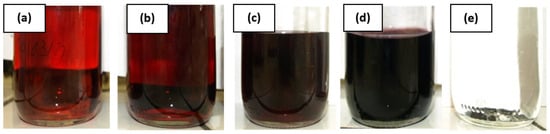
Figure 3.
Gold nanoparticle solutions synthesized with different gold concentrations of (a) 0.25 mmol·L−1, (b) 0.49 mmol·L−1, (c) 1.5 mmol·L−1, (d) 3.3 mmol·L−1, and (e) 6.4 mmol·L−1.
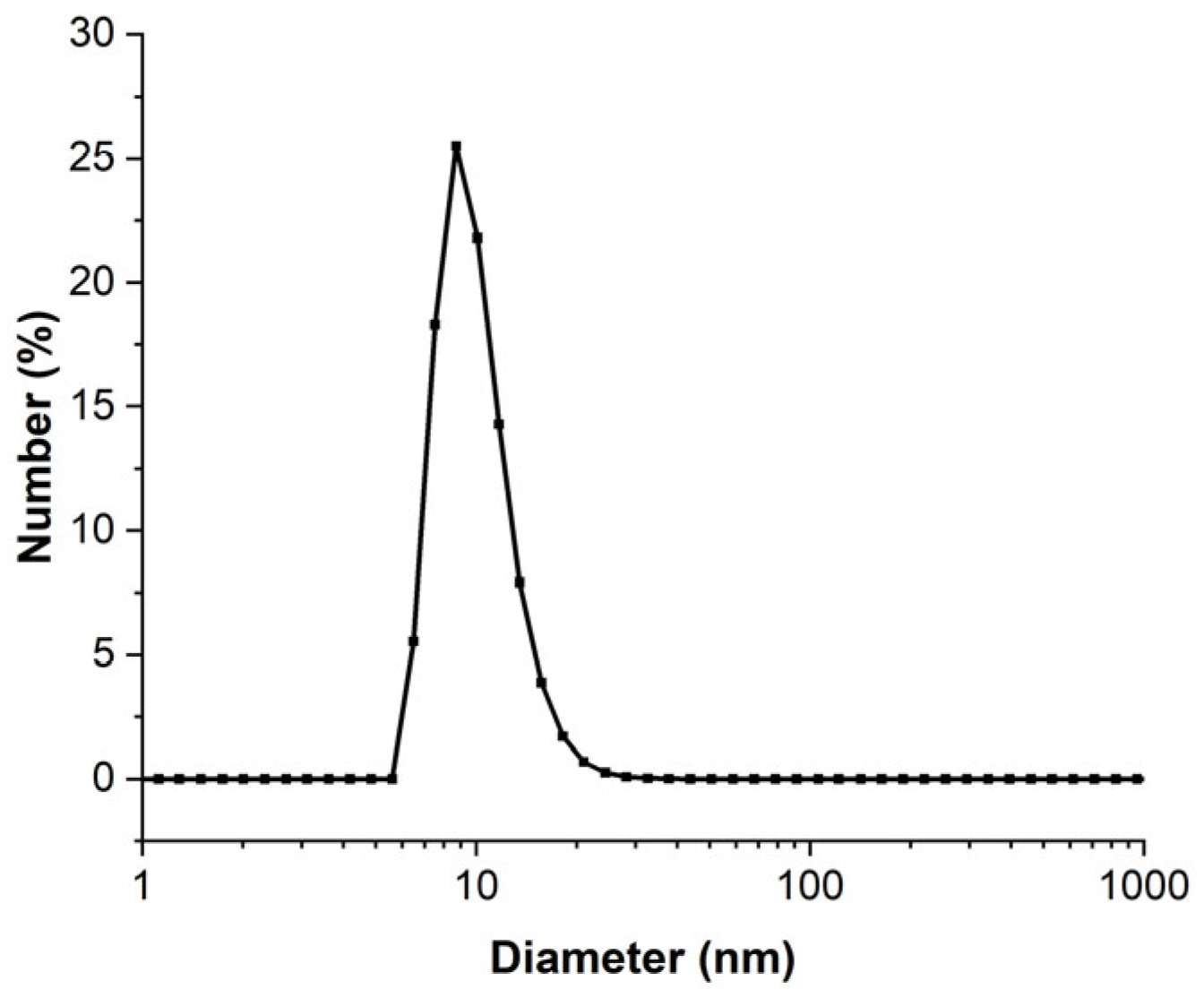
The concentrated 3.3 mmol·L−1 AuNPs that were obtained were analyzed using DLS to determine the particle distribution in liquid media. The DLS diameter distribution presented in Figure 4 shows that the AuNPs in solution have a mean diameter of 8.5 nm and 95% of these particles have a diameter inferior to 20 nm. By increasing the concentration of the AuNP solution, the mean diameter and the size dispersion were increased. The mean diameters were 5.5 nm and 8.5 nm for the less-concentrated (0.25 mmol·L−1) solution and the most concentrated solution (3.3 mmol·L−1), respectively. The diameter obtained by analysis in number was different from the real NP diameter because some approximations such as refractive index (which depends on the AuNP size) were made [44]. Moreover, the DLS method fundamentally requires the analysis of an extremely diluted solution [45], which was not necessarily compatible with our experimental conditions. This is why DLS data must be consolidated with another diameter characterization technique.
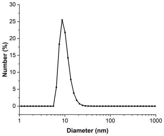
Figure 4.
DLS of 3.3 mmol·L−1 AuNP solution analyzed in number of particles.
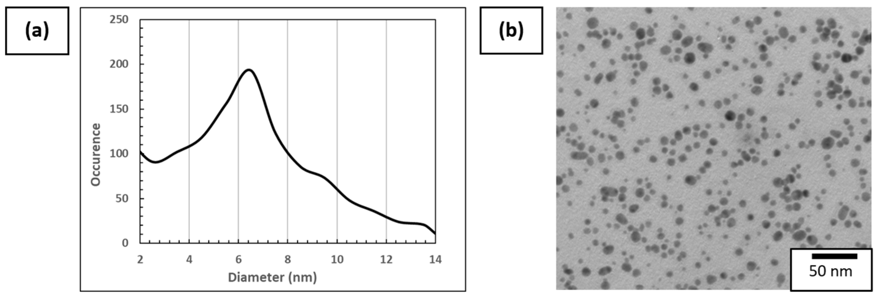
TEM was therefore used to determine the aspect and diameter of dried AuNPs deposited on the Cu/C TEM grid. The diameter was obtained by image analysis of more than 800 AuNPs made with ImageJ software (1.53t version), as can be seen in Figure 5a. An example of a TEM image used for plotting the distribution of diameter is presented in Figure 5b. The AuNP mean diameter is 6.5 nm and the diameter range of AuNPs varies from 2 nm to 15 nm, which is in accordance with the DLS measurements. It is considered that <2 nm diameter particles are artifacts due to the data processing method. These values are superior to the value provided by Piella et al. [40], which is explained by the modification in the synthesis to increase the AuNP solution concentration.
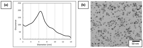
Figure 5.
(a) Distribution of AuNP size using more than 800 particles on different areas of the Cu/C TEM grid and (b) example of TEM images of 3.3 mmol·L−1 AuNP solution used for this analysis.
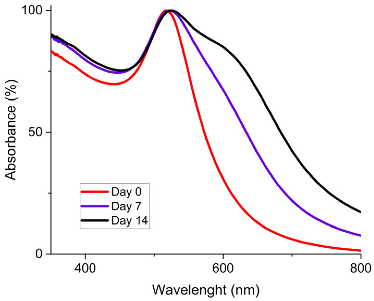
To characterize the stability of the concentrated AuNP solution, UV-vis spectrometry was used. Initially, the synthesis method of Piella et al. provided a long-term stable AuNP solution that could be stored for several months [40]. Then, the selected concentrated AuNP solution stability was analyzed. The freshly synthesized AuNP solution exhibited a single absorption peak around 520 nm as shown by the UV–visible spectrum presented in Figure 6. The presence of a single peak at a low wavelength value is representative of the presence of 10 nm diameter particles in solution. This observation means that there is no agglomeration of the particles at this stage. Then, after seven days, the solution tended to destabilize as shown by the growth of a characteristic peak on the UV-Vis curves located near 600 nm, which is frequently described in the literature [40,46]. This second peak intensity increased for 14 days. This means that AuNPs were not stabilized and tended to agglomerate. This agglomeration is also shown by a red-to-blue shift of the solution after seven and fourteen days. After 30 days, partial sedimentation of the AuNP solution was observable, as shown in Figure 7a.

Figure 6.
UV-Vis spectrum for 3.3 mmol·L−1 AuNP solution at different aging times with fresh AuNPs (red), after 7 days (purple), and after 14 days (black).

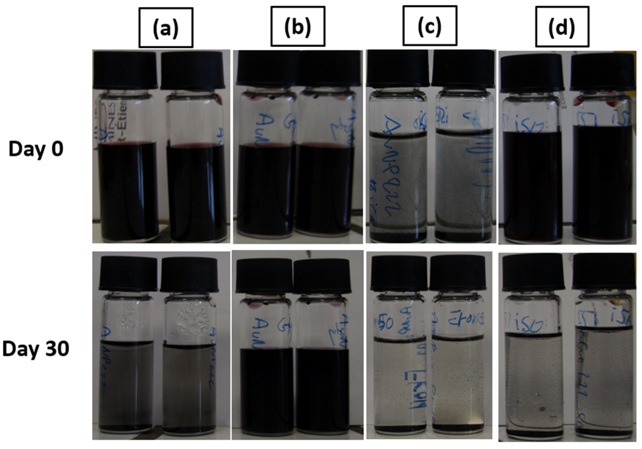
Figure 7.
Stability test for (a) AuNP solution; (b) AuNPs + 55% wt. glycerol; (c) AuNPs + 50% wt. propan-2-ol; (d) AuNPs + 55% wt. glycerol + 10% wt. propan-2-ol, with the 3.3 mmol·L−1 AuNP solution.
AuNP solutions were further characterized for the determination of their viscosity and surface tension. Those properties have to be adjusted to fit the requirements of the printer and the cartridge types. Initially, AuNP solutions have a 72.0 mN·m−1 surface tension and a 1.1 mPa·s viscosity. These values must be decreased for surface tension (range: 28–33 mN·m−1) and increased for viscosity (range 8–12 mPa·s), respectively, to be suitable for inkjet printing.
3.1.2. AuNP Inks
For the ink formulation, the goal is to obtain an acceptable value for surface tension and viscosity by adding property modifiers to the AuNP solution without destabilizing the AuNP suspension in order to avoid nozzle clogging.
The modification of surface tension and viscosity was achieved with the addition of rheological and surface tension modifiers such as glycerol or propan-2-ol directly into the AuNP solutions. The specific properties of these solvents are shown in Table 3.
Table 3.
Solvents used for formulation with their theoretical surface tension and viscosity values at 20 °C and ambient conditions.
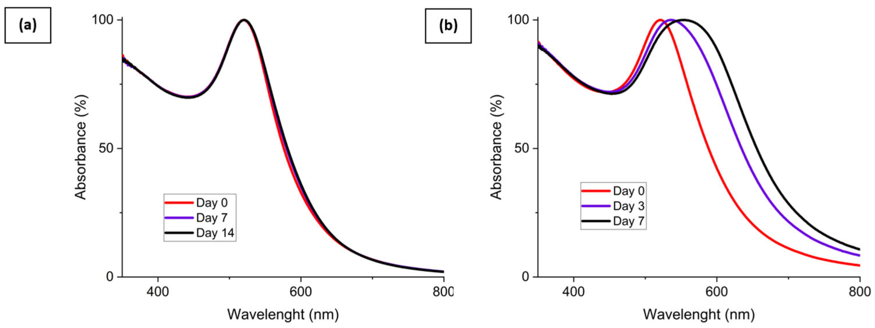
The stability of the mixture made of the AuNP solution and the surface tension and viscosity modifier was evaluated and is shown in Figure 7. AuNP solutions can be seen in Figure 7a and were stable after synthesis. However, these AuNP solutions tended to slowly destabilize, as shown previously by the UV-Vis data. Figure 7b corresponds to the AuNP solution mixed with 55% wt. of glycerol. In this case, the solution is still stable after 30 days. This behavior is also shown by the UV-Vis spectrum presented in Figure 7a. The viscosity increase is supposed to be responsible for the improved stability of the mixture. The addition of a surface tension modifier such as propan-2-ol, 50% wt. here, as shown in Figure 7c, destabilizes the AuNP solution and leads to a rapid sedimentation of the particles within 1 h. Finally, as shown in Figure 7d, an intermediate behavior is observed for the mixture made of AuNP solution, glycerol, and propan-2-ol. The solution tends to destabilize over time and is partially sedimented after 30 days, as could be observed with the AuNP solution. This destabilization behavior is highlighted by the UV-Vis spectrum of the AuNP solution, glycerol, and propan-2-ol mixture shown in Figure 8b. However, no precipitation occurs in a week for this ink.
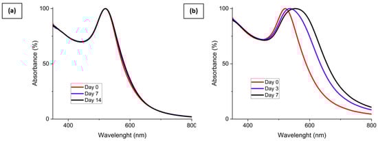
Figure 8.
UV-Vis spectrum of (a) 3.3 mmol·L−1 AuNP solution with 55% wt. glycerol addition and (b) 3.3 mmol·L−1 AuNP solution with 55% wt. glycerol and 10% wt. propan-2-ol addition at different aging times.
In order to obtain a printable ink, regarding the Dimatix printer requirements, the composition was adjusted. The optimal AuNP ink formulation was determined to fulfill the requirements and is:
- -
- 35% wt. of AuNP concentrated solution;
- -
- 55% wt. of Glycerol;
- -
- 10% wt. of isopropanol (propan-2-ol).
The ink properties obtained possessed a surface tension of 32 mN·m−1 and a 11.2 mPa·s viscosity.
To overcome the destabilization issue shown before, for period longer than one week, the ink preparation can be segmented. First, the mixture glycerol-stabilized AuNP solution can be stored for months before the addition of a surface tension modifier. Then, the propan-2-ol addition is needed for the ink formulation; however, we showed that it was directly responsible for the ink destabilization. That is why the addition of propan-2-ol must be performed shortly before starting printing the ink. This ink made up of a mixture of a concentrated AuNP solution, glycerol and propa-2-ol, and is sufficiently stable up to 7 days after addition of propan-2-ol. This mean that ink is suitable for the inkjet printing process. Then, after 7 days, the destabilization of the ink is considered to be too significant, thus the ink is no longer able to be used for printing.
3.1.3. Inkjet Printing of AuNP Ink
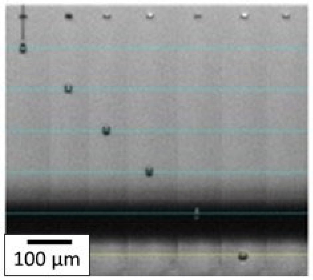
With the optimized ink, the printing parameters were then adjusted to eject the spherical drops without satellite droplets. First, the waveform was optimized, and as mentioned in the experimental section, a trapezoidal one was chosen for this study. The maximum voltage applied was varied from 18 V to 30 V. In our case, the time during which the maximum voltage was applied was fixed at 3 µs. The highest voltage stage was maintained for 3 µs and the zero-voltage stage was held for 6 µs to stabilize the ink ejection. The slew rate was fixed on the software to be as fast as possible. The temperature of the nozzles was also a crucial parameter, as both viscosity and surface tension depend on temperature, and was fixed at 35 °C. These settings allowed the AuNP inks to be ejected from the nozzles without satellite droplets and without spraying at a convenient speed of 3.6 m·s−1. As can be seen in Figure 9, the droplets are spherical with no satellite drops and the tail quickly reattached to the drop 100 µm after leaving the nozzle. It ensures that when the droplet hits the substrate placed 1000 µm under the nozzle, it is entirely spherical with no excess fluid.
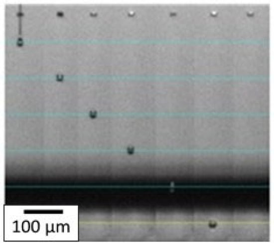
Figure 9.
Droplet ejection through the nozzle by inkjet printing process for AuNP ink. Each horizontal blue line corresponds to a 100 µm distance and the jetting time (in µs) of each droplet is written on top of each corresponding nozzle.
3.1.4. AuNP Deposition
Polymer substrates were chosen due to their good flexibility, low coating, and increasing use in the gas sensor industry. For application purposes, the substrate must be able to withstand a 400 °C thermal treatment without being degraded or distorted. Temperatures up to this value could be used to allow the sensor to work and detect gases. Thus, a polyimide (PI) foil was selected due to its high chemical and thermal stability.
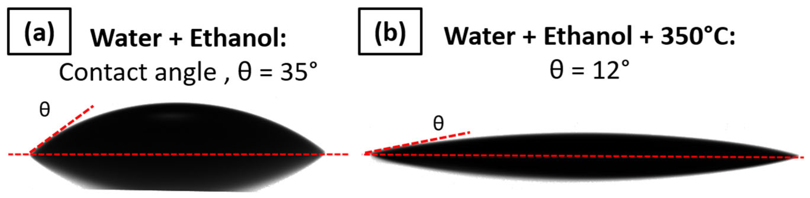
However, the wettability of the PI substrate will have a contribution to the final coating. The purpose is to have the lowest contact angle value between the PI foil and selected ink to ensure proper deposition. This value was determined using multiple screenshots of the sessile drop in order to determine the contact angle between the ink and PI substrate.
A different type of cleaning method with water and ethanol was tested. The only significant effect in terms of contact angle decrease was obtained by heating the PI substrate at 350 °C for 1 h after the cleaning. This allows the contact angle θ to be decreased from 35° ± 2° to 12° ± 2°, which is suitable for ink deposition; the wettability is shown in Figure 10. Thus, the cleaning followed by thermal heating at 350 °C will be performed before the printing.
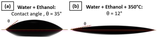
Figure 10.
Contact angle measured between AuNP ink and (a) PI foil cleaned with water and ethanol rinsing and (b) PI foil cleaned with water and ethanol followed by thermal heating at 350 °C for 1 h.
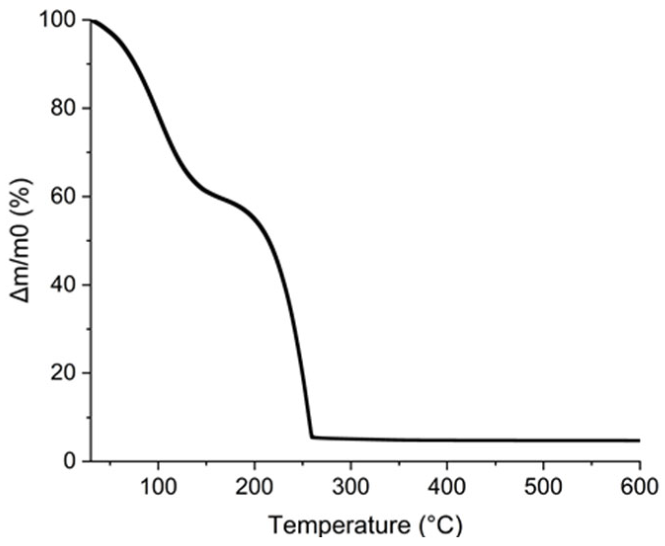
Furthermore, the additives in the ink must be eliminated by a thermal treatment lower than the polyimide degradation temperature. To verify that all the organic parts contained in the ink were removed at this temperature, a TGA analysis was completed and reported in Figure 11. The first mass loss was attributed to the evaporation of propan-2-ol and water near 100 °C. This is confirmed by the calculation of the percentage eliminated. The water and propan-2-ol mass losses observed by TGA are 40% wt. which corresponds to the 45% wt. of AuNPs added to the ink considering that gold loading is 5% wt. The second mass loss from 150 to 260 °C corresponds to the loss of 55% wt. of the ink and was attributed to glycerol for which the boiling point is 290 °C [52]. It is noteworthy that all the organics composing the ink are removed below 260 °C which is compatible with PI substrate.
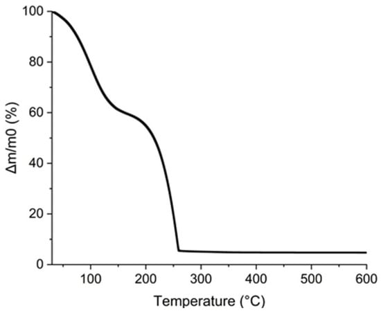
Figure 11.
TGA curve of AuNPs, glycerol, and propan-2-ol ink.
Inkjet printing deposition was then optimized through a variation in spaces between drops called drop spacing (DS) relative to the X-axis (DSX) and Y-axis (DSY). First, a drop deposited on PI corresponds to a point of 37 µm in diameter according to the observations made by the Dimatix camera. To print a pattern, modification of the distance between each drop is performed, leading to an optimal drop deposition where the lines are homogeneous without apparent defects. Figure 12 compiles the patterns obtained while varying the DSX and DSY parameters. A 20 µm distance between drops is optimal on the X-axis and allows a continuous 1D line in width to be obtained, as shown in Figure 12a. A greater distance leads to discontinuous lines and a smaller distance leads to beveled edges. The importance of this parameter on the pattern obtained was also shown by Soltman and Subramanian [53].
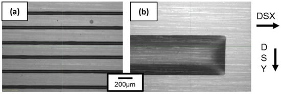
Figure 12.
Ink lines obtained with optimized drop-spacing parameters which are (a) 20 µm distance between each drop on X-axis and 200 µm distance on Y-axis and (b) 20 µm on X-axis and 5 µm on Y-axis.
The DSY parameter translates the distance between each line. A DSY value of 200 µm between the lines shows well-separated lines in Figure 12a. By decreasing DSY, the distance is diminished and overlapping starts to occur with a partial coverage of the ink onto the PI substrate. Decreasing DSY to 5 µm leads homogeneous 2D lines being obtained, as shown in Figure 12b. According to previous thermal analysis, all patterns were dried in an oven at 110 °C for 15 min to evaporate most of the solvents like propanol-2-ol and water. A final thermal treatment temperature of 350 °C was made for 3 h with a 2 °C min−1 ramp. These values are in accordance with those referenced in the literature [12].
The patterns obtained with one deposited layer were not conductive because the percentage loading of the AuNP ink is about 5% wt., as previously shown by TGA analysis. To increase the quantity of AuNPs deposited onto the PI substrate, the number of layers deposited was increased and the optimal number of layers was investigated. By increasing the number of layers, resolution issues appeared. To avoid this effect, a solvent evaporation in an oven at 110 °C was made every 5 printed layers in order to evaporate solvent excess. Finally, the fixed number of layers printed was fixed at 100 layers.
3.1.5. Characterizations of the AuNP Coatings
The deposition made of 100 layers and sintered at 350 °C for 3 h was set as the reference for the AuNP coating. Figure 13 shows an SEM image of the deposit that is made of small randomly dispersed AuNP particles. These particles are not interconnected even with 100 layers. This means that the amount of gold deposited is not high enough to obtain a conductive coating on polyimide with 100 layers deposited. The chosen AuNP solution was the most concentrated that had been synthesized before obtaining sedimentation, which means that the concentration cannot be increased. The number of layers is a variable parameter that can allow the amount of gold deposited to be increased. Nevertheless, increasing this layer number will be time-consuming and will result in a decrease in the resolution and maybe the quality of the printed layers.
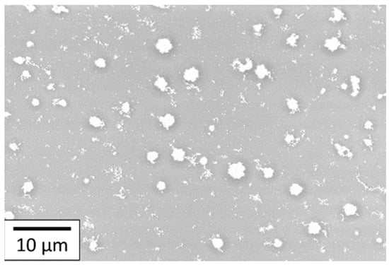
Figure 13.
SEM images of 100 layers of AuNP coating deposited onto the PI substrate.
The development of AuNP ink has led to non-homogeneous gold coating without enough matter to cover the substrate and have a continuous gold coating. Nevertheless, to overcome this issue, a new ink was developed with a higher gold concentration, as described in the following section.
3.2. Precursor Ink Development
A new approach was investigated, using directly HAuCl4.6H2O as the gold precursor in the ink. Firstly, the gold salt was solubilized in water, the concentration of 0.4 mol·L−1 being chosen to be close to the gold precursor solubility limit in water, which is 150 g·L−1. Then, this solution was mixed with ethylene glycol (22.3 mPa·s [54] and 49.1 mN·m−1 [55]) and propan-2-ol to obtain an ink. The optimal ink properties were reached with a 20% wt. water, 70% wt. ethylene glycol, and 10% wt. propan-2-ol mixture. This ink was suitable for the inkjet process due to its parameters such as 32 mN·m−1 surface tension and 14.0 mPa.s viscosity.
Therefore, the gold concentration of this ink mixture was only 0.1 mol·L−1 due to the addition of ethylene glycol and propan-2-ol.
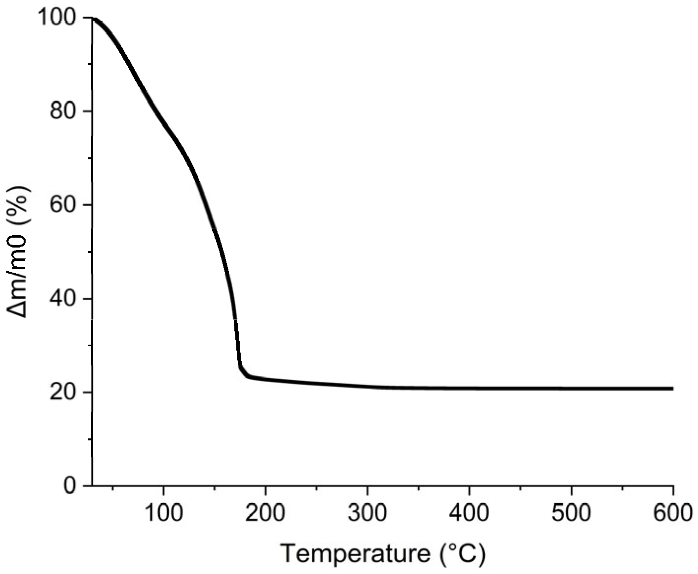
In order to increase this gold concentration, a gold precursor was directly dissolved in propan-2-ol, ethylene glycol, and water mixture. The gold precursor quantity added to the mixture was increased by successive small additions until reaching the most concentrated solution corresponding to 1.6 mol·L−1 of gold salt, HAuCl4·6H2O, in the final ink composition. The rheological and surface tension properties remained at 32 mN·m−1 and 14.0 mPa·s. This 1.6 mol·L−1 precursor ink was further investigated using thermal analysis and the TGA/DSC graph is presented in Figure 14. Mass loss shows that there is a first step before 100 °C where water and propan-2-ol evaporate. Then, between 100 °C and 200 °C, a huge mass loss is observed and completed at 184 °C. This is compatible with the elimination of ethylene glycol occurring theoretically at 197.6 °C [56]. The total mass loss was 80% wt. meaning that the gold loading in the ink represents 20% wt. of the mixture.
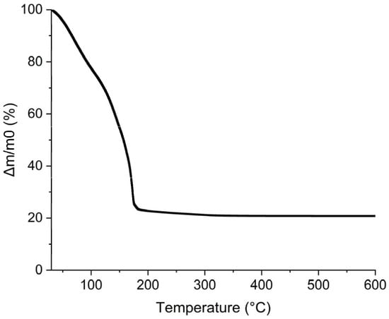
Figure 14.
TGA curve for 1.6 M precursor ink.
For ink jetting, the trapezoidal waveform has also been used with a maximum voltage duration held for 1.5 µs and zero voltage for 3 µs. The voltage applied was varied to determine the optimal range in values to correctly eject the ink. This value is identified between 24 and 30 V. That is why, as observed in Figure 9, the speed of droplets is at least 4.6 m·s−1, and the tail reattachment is slightly delayed around 200–300 µm which is suitable for the inkjet process. Optimal drop spacing values found were 20 µm DSX and 50 µm DSY. This led to wet patterns with very well-defined edges.
For the precursor ink deposition, the PI substrate did not need to be thermally pre-heated to increase its wettability. In this case, the PI substrate was only cleaned with water and ethanol and then dried with air. It can be explained by the fact that the surface tension of the pure ethylene glycol composing this ink is 49.1 mN·m−1 at 20 °C [55], whereas glycerol surface tension, composing the AuNP ink, is 63.1 mN·m−1 at the same temperature of 20 °C [49]. Thus, after volatile solvent evaporation, the ink wetting is increased and it allows the shrinkage to be reduced.
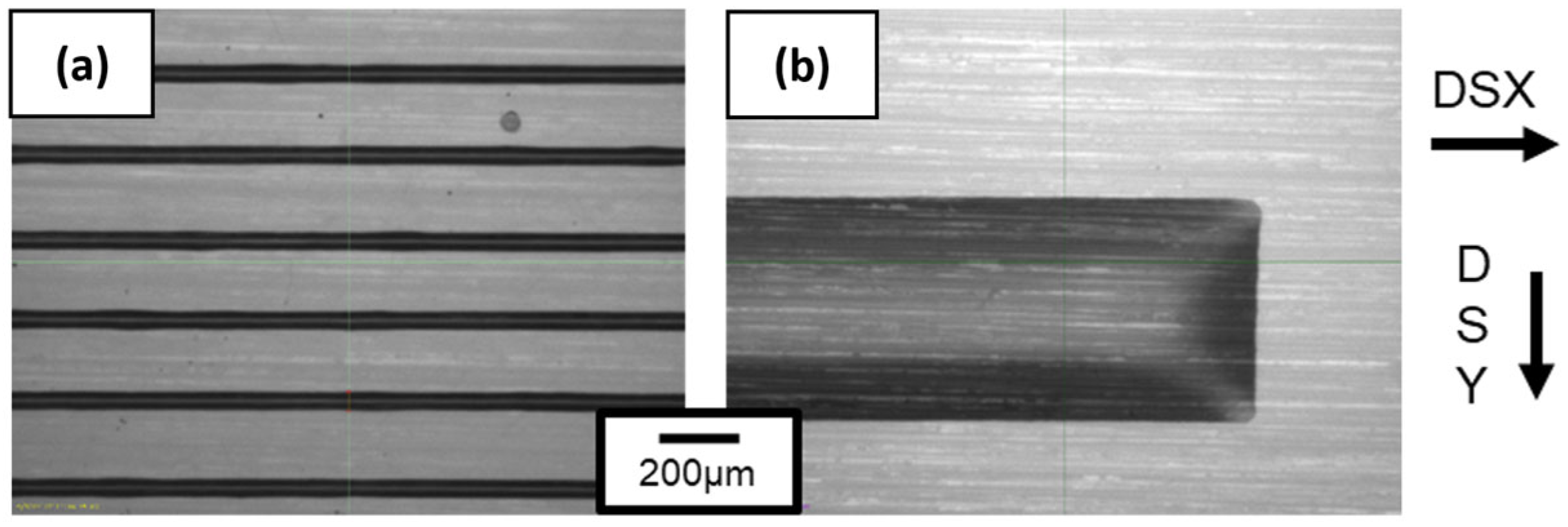
Finally, the deposition technique of precursor ink onto the substrate was optimized to obtain a homogeneous gold coating. It was noticed that multiple layers were necessary to have a thick gold layer. To have well-defined samples, a heating step was performed to remove the solvent excess after several consecutive layers were printed. These evaporation steps were performed at 110 °C for 20 min in an oven followed by a thermal treatment at 350 °C for 2 h. As shown in Figure 15 in the macroscopic pictures, for 40 layers of deposited coating with a drying step every 20 layers (Figure 15a), the ink is spilling out of the pattern area due to solvent excess. This phenomenon is also observed for a 40 layer coating dried every 10 layers, as presented in Figure 15b. By drying every five layers that were printed onto the PI foils, a homogenous layer was obtained with a high resolution and well-defined edges for the 60 layer coating, as shown in Figure 15c.

Figure 15.
Pictures of (a) 40 layers of coating printed 20 layers by 20 layers; (b) 40 layers of coating printed 10 layers by 10 layers; and (c) 60 layers of coating printed 5 layers by 5 layers onto PI foils of a 2.5 cm length pattern printed.
This protocol was repeated 6 and 12 times to obtain a 30 and a 60 layer coating to figure out the best number of layers needed to obtain conductive coatings. SEM micrographs are shown in Figure 16 for a 30 and a 60 layer inkjet printing gold precursor coating. The SEM comparison shows that the gold quantity deposited with 60 layers is considerably better than the 30 layer coating. Below 60 layers, the gold film is not conductive because there is too much porosity in the structure. For 60 layers as shown here, the percentage covered by gold is greater than 93%, while the coverage is about 80% for 30 layers. A cross-section of the coating was made using FIB and inspected with SEM to determine its thickness. For the coating made of 60 layers, the thickness value was estimated at around 1.5 µm.
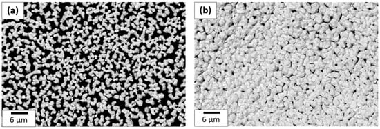
Figure 16.
SEM image comparison of (a) 30 and (b) 60 layer coating made with 1.6 M precursor ink deposited onto PI.
These coatings are conductive and measurement through a four-point probe was taken. The calculation of material resistivity gave a value of 2 × 10⁻⁷ Ω·m, which is 10 times higher than bulk gold, comparable to gold films obtained by this type of process. Mekhoumken et al. obtained 1.0 × 10⁻⁷ Ω·m for a gold coating made from an ecofriendly homemade gold nanoparticle ink; meanwhile, Maättänen et al. described 1.6 × 10⁻⁷ Ω·m of an electrode deposited with NaBH4-reduced gold nanoparticle ink and Nitta et al. obtained resistivity of 7.21 × 10⁻⁶ Ω·m with a particle-free ink [38,57,58].
4. Conclusions
AuNP inks were formulated from gold nanoparticles synthesized in an aqueous medium. This ink was formulated to have a surface tension of 32 mN·m−1 and a viscosity of 11.2 mPa·s with 55% wt. glycerol, 35% wt. AuNP solution, and 10% wt. propan-2-ol ink. All inkjet-printing parameters were optimized from nozzle temperature to the drop spacing including waveform modifications. The number of layers deposited and thermal treatment were also evaluated and characterizations showed that the amount of gold deposited with 100 layers was not sufficient to obtain conductive electrodes. A second methodology developed to obtain conductive coatings was to solubilize a gold precursor (HAuCl4) into a mixture of ethylene glycol, water, and propan-2-ol. The rheological properties were measured and adjusted as well as the printing process to obtain a 32 mN·m−1 surface tension and 14.0 mPa·s viscosity printable ink. The precursor ink of 1.6 M concentration was deposited on the PI foils. In this case, 60 layers of gold deposited tended to form an interconnected network, the obtained layer being homogeneous and continuous. The conductivity of 60 layers of gold coating was evaluated at 2 × 10⁻⁷ Ω·m with a four-point probes system. These inkjet-printed gold coatings on flexible PI foils could be further used for electrodes of metal oxide gas sensors or multiple other applications that need gold layers.
Author Contributions
Conceptualization: B.L.P., M.R. and J.-P.V.; investigation: B.L.P.; validation: B.L.P. and M.R.; writing—original draft: B.L.P.; writing—review and editing: B.L.P., M.R. and J.-P.V.; Funding acquisition: M.R. and J.-P.V.; supervision, M.R. and J.-P.V. All authors have read and agreed to the published version of the manuscript.
Funding
This research received no external funding.
Data Availability Statement
Data available on demand to the corresponding author.
Acknowledgments
The authors thank Sergio Sao Joao, Ecole des Mines de Saint-Etienne; 158 Cours Fauriel; 42100; Saint-Etienne; France, for the TEM images.
Conflicts of Interest
The authors declare no conflicts of interest.
References
- Wales, D.J.; Grand, J.; Ting, V.P.; Burke, R.D.; Edler, K.J.; Bowen, C.R.; Mintova, S.; Burrows, A.D. Gas sensing using porous materials for automotive applications. Chem. Soc. Rev. 2015, 44, 4290–4321. [Google Scholar] [CrossRef] [PubMed]
- Fine, G.F.; Cavanagh, L.M.; Afonja, A.; Binions, R. Metal Oxide Semi-Conductor Gas Sensors in Environmental Monitoring. Sensors 2010, 10, 5469–5502. [Google Scholar] [CrossRef] [PubMed]
- Kumar, P.; Skouloudis, A.N.; Bell, M.; Viana, M.; Carotta, M.C.; Biskos, G.; Morawska, L. Real-time sensors for indoor air monitoring and challenges ahead in deploying them to urban buildings. Sci. Total Environ. 2016, 560–561, 150–159. [Google Scholar] [CrossRef] [PubMed]
- Paliwal, A.; Sharma, A.; Tomar, M.; Gupta, V. Carbon monoxide (CO) optical gas sensor based on ZnO thin films. Sens. Actuators B Chem. 2017, 250, 679–685. [Google Scholar] [CrossRef]
- Zhang, P.; Xiao, Y.; Zhang, J.; Liu, B.; Ma, X.; Wang, Y. Highly sensitive gas sensing platforms based on field effect Transistor—A review. Anal. Chim. Acta 2021, 1172, 338575. [Google Scholar] [CrossRef] [PubMed]
- Imai, Y.; Tadaki, D.; Ma, T.; Kimura, Y.; Hirano-Iwata, A.; Niwano, M. Response characteristics of hydrogen gas sensor with porous piezoelectric poly(vinylidene fluoride) film. Sens. Actuators B Chem. 2017, 247, 479–489. [Google Scholar] [CrossRef]
- Khan, M.; Rao, M.; Li, Q. Recent Advances in Electrochemical Sensors for Detecting Toxic Gases: NO2, SO2 and H2S. Sensors 2019, 19, 905. [Google Scholar] [CrossRef] [PubMed]
- Wang, C.; Yin, L.; Zhang, L.; Xiang, D.; Gao, R. Metal Oxide Gas Sensors: Sensitivity and Influencing Factors. Sensors 2010, 10, 2088–2106. [Google Scholar] [CrossRef]
- Dey, A. Semiconductor metal oxide gas sensors: A review. Mater. Sci. Eng. B 2018, 229, 206–217. [Google Scholar] [CrossRef]
- Izawa, K.; Ulmer, H.; Staerz, A.; Weimar, U.; Barsan, N. Application of SMOX-based sensors. In Gas Sensors Based on Conducting Metal Oxides; Elsevier: Amsterdam, The Netherlands, 2019; pp. 217–257. [Google Scholar]
- Isaac, N.A.; Pikaar, I.; Biskos, G. Metal oxide semiconducting nanomaterials for air quality gas sensors: Operating principles, performance, and synthesis techniques. Microchim. Acta 2022, 189, 196. [Google Scholar] [CrossRef]
- Rieu, M.; Camara, M.; Tournier, G.; Viricelle, J.P.; Pijolat, C.; de Rooij, N.F.; Briand, D. Fully inkjet printed SnO2 gas sensor on plastic substrate. Sens. Actuators B Chem. 2016, 236, 1091–1097. [Google Scholar] [CrossRef]
- Viricelle, J.-P.; Riviere, B.; Pijolat, C. Optimization of SnO2 screen-printing inks for gas sensor applications. J. Eur. Ceram. Soc. 2005, 25, 2137–2140. [Google Scholar] [CrossRef]
- Lee, Y.C.; Huang, H.; Tan, O.K.; Tse, M.S. Semiconductor gas sensor based on Pd-doped SnO2 nanorod thin films. Sens. Actuators B Chem. 2008, 132, 239–242. [Google Scholar] [CrossRef]
- Alrammouz, R.; Podlecki, J.; Abboud, P.; Sorli, B.; Habchi, R. A review on flexible gas sensors: From materials to devices. Sens. Actuators A Phys. 2018, 284, 209–231. [Google Scholar] [CrossRef]
- Qian, X.; Ko, A.; Li, H.; Liao, C. Flexible non-enzymatic glucose strip for direct non-invasive diabetic management. Microchem. J. 2024, 197, 109818. [Google Scholar] [CrossRef]
- Yan, K.; Li, J.; Pan, L.; Shi, Y. Inkjet printing for flexible and wearable electronics. APL Mater. 2020, 8, 120705. [Google Scholar] [CrossRef]
- Vänskä, E.; Luukka, M.; Solala, I.; Vuorinen, T. Effect of water vapor in air on thermal degradation of paper at high temperature. Polym. Degrad. Stab. 2014, 99, 283–289. [Google Scholar] [CrossRef]
- Hawkins, W.L. Polymer Degradation and Stabilization; Springer: Berlin/Heidelberg, Germany, 1984. [Google Scholar]
- Geller, R.F.; Yavorsky, P.J. Melting point of alpha-alumina. Part J. Res. Natl. Bur. Stand. 1945, 34, 395–401. [Google Scholar] [CrossRef]
- Chang, W.Y.; Fang, T.H.; Lin, H.J.; Shen, Y.T.; Lin, Y.C. A Large Area Flexible Array Sensors Using Screen Printing Technology. J. Disp. Technol. 2009, 5, 178–183. [Google Scholar] [CrossRef]
- Gong, X.; Huang, K.; Wu, Y.-H.; Zhang, X.-S. Recent progress on screen-printed flexible sensors for human health monitoring. Sens. Actuators A Phys. 2022, 345, 113821. [Google Scholar] [CrossRef]
- Derby, B. Inkjet printing ceramics: From drops to solid. J. Eur. Ceram. Soc. 2011, 31, 2543–2550. [Google Scholar] [CrossRef]
- Cummins, G.; Desmulliez, M.P.Y. Inkjet printing of conductive materials: A review. Circuit World 2012, 38, 193–213. [Google Scholar] [CrossRef]
- Derby, B. Inkjet Printing of Functional and Structural Materials: Fluid Property Requirements, Feature Stability, and Resolution. Annu. Rev. Mater. Res. 2010, 40, 395–414. [Google Scholar] [CrossRef]
- Lee, B.-B.; Ravindra, P.; Chan, E.-S. A critical review: Surface and interfacial tension measurement by the drop weight method. Chem. Eng. Commun. 2008, 195, 889–924. [Google Scholar] [CrossRef]
- Krainer, S.; Smit, C.; Hirn, U. The effect of viscosity and surface tension on inkjet printed picoliter dots. RSC Adv. 2019, 9, 31708–31719. [Google Scholar] [CrossRef] [PubMed]
- Dimatix. Jettable Fluid Formulation Guidelines; Fujifilm-Dimatix: Santa Clara, CA, USA, 2013. [Google Scholar]
- Fernandes, I.J.; Aroche, A.F.; Schuck, A.; Lamberty, P.; Peter, C.R.; Hasenkamp, W.; Rocha, T.L. Silver nanoparticle conductive inks: Synthesis, characterization, and fabrication of inkjet-printed flexible electrodes. Sci. Rep. 2020, 10, 8878. [Google Scholar] [CrossRef] [PubMed]
- Yang, W.; List-Kratochvil, E.J.W.; Wang, C. Metal particle-free inks for printed flexible electronics. J. Mater. Chem. C 2019, 7, 15098–15117. [Google Scholar] [CrossRef]
- Degler, D.; Weimar, U.; Barsan, N. Current Understanding of the Fundamental Mechanisms of Doped and Loaded Semiconducting Metal-Oxide-Based Gas Sensing Materials. ACS Sens. 2019, 4, 2228–2249. [Google Scholar] [CrossRef] [PubMed]
- Carvalho, H.W.P.; Degler, D.; Barsan, N.; Grunwaldt, J.-D. Sensors. In XAFS Techniques for Catalysts, Nanomaterials, and Surfaces; Iwasawa, Y., Asakura, K., Tada, M., Eds.; Springer International Publishing: Cham, Switzerland, 2017; pp. 383–396. [Google Scholar]
- OrelTech Aurum. Available online: https://oreltech.com/products (accessed on 19 December 2023).
- HARIMA CHEMICALS, Inc. Available online: https://www.harima.co.jp/en/ (accessed on 19 December 2023).
- ULVAC, Inc. Au NANOMETAL INK. Available online: https://www.ulvac.co.jp/en/products/materials/nano_metal_ink/au/index.html (accessed on 19 December 2023).
- SicrysTM IAu20W. Available online: https://www.pvnanocell.com/gold-ink.html (accessed on 19 December 2023).
- Jensen, G.C.; Krause, C.E.; Sotzing, G.A.; Rusling, J.F. Inkjet-printed gold nanoparticle electrochemical arrays on plastic. Application to immunodetection of a cancer biomarker protein. Phys. Chem. Chem. Phys. 2011, 13, 4888. [Google Scholar] [CrossRef]
- Mekhmouken, S.; Battaglini, N.; Mattana, G.; Maurin, A.; Zrig, S.; Piro, B.; Capitao, D.; Noel, V. Gold nanoparticle-based eco-friendly ink for electrode patterning on flexible substrates. Electrochem. Commun. 2021, 123, 106918. [Google Scholar] [CrossRef]
- Schoner, C.; Tuchscherer, A.; Blaudeck, T.; Jahn, S.F.; Baumann, R.R.; Lang, H. Particle-free gold metal–organic decomposition ink for inkjet printing of gold structures. Thin Solid Films 2013, 531, 147–151. [Google Scholar] [CrossRef]
- Piella, J.; Bastús, N.G.; Puntes, V. Size-Controlled Synthesis of Sub-10-nanometer Citrate-Stabilized Gold Nanoparticles and Related Optical Properties. Chem. Mater. 2016, 28, 1066–1075. [Google Scholar] [CrossRef]
- Sheely, M.L. Glycerol Viscosity Tables. Ind. Eng. Chem. 1932, 24, 1060–1064. [Google Scholar] [CrossRef]
- Bohne, D.; Fischer, S.; Obermeier, E. Thermal, Conductivity, Density, Viscosity, and Prandtl-Numbers of Ethylene Glycol-Water Mixtures. Berichte Bunsenges. Phys. Chem. 1984, 88, 739–742. [Google Scholar] [CrossRef]
- Vazquez, G.; Alvarez, E.; Navaza, J.M. Surface Tension of Alcohol Water + Water from 20 to 50 °C. J. Chem. Eng. Data 1995, 40, 611–614. [Google Scholar] [CrossRef]
- Zheng, T.; Bott, S.; Huo, Q. Techniques for Accurate Sizing of Gold Nanoparticles Using Dynamic Light Scattering with Particular Application to Chemical and Biological Sensing Based on Aggregate Formation. ACS Appl. Mater. Interfaces 2016, 8, 21585–21594. [Google Scholar] [CrossRef] [PubMed]
- Bhattacharjee, S. DLS and zeta potential—What they are and what they are not? J. Control. Release 2016, 235, 337–351. [Google Scholar] [CrossRef] [PubMed]
- Shafiqa, A.R.; Abdul Aziz, A.; Mehrdel, B. Nanoparticle Optical Properties: Size Dependence of a Single Gold Spherical Nanoparticle. J. Phys. Conf. Ser. 2018, 1083, 012040. [Google Scholar] [CrossRef]
- Vargaftik, N.B.; Volkov, B.N.; Voljak, L.D. International Tables of the Surface Tension of Water. J. Phys. Chem. Ref. Data 1983, 12, 817–820. [Google Scholar] [CrossRef]
- Swindells, I.F.; Coe, J.R. Absolute Viscosity of Water at 20 °C. J. Res. Natl. Bur. Stand. 1952, 48. Available online: https://www.google.com/url?sa=t&source=web&rct=j&opi=89978449&url=https://nvlpubs.nist.gov/nistpubs/jres/048/1/V48.N01.A01.pdf&ved=2ahUKEwiC5pzQwrCGAxWShP0HHVSFDOoQFnoECA4QAQ&usg=AOvVaw0qL9EJGBjcsK1GfT8H2U0I (accessed on 18 April 2024). [CrossRef]
- Erfani, A.; Khosharay, S.; Aichele, C.P. Surface tension and interfacial compositions of binary glycerol/alcohol mixtures. J. Chem. Thermodyn. 2019, 135, 241–251. [Google Scholar] [CrossRef]
- Alkindi, A.S.; Al-Wahaibi, Y.M.; Muggeridge, A.H. Physical Properties (Density, Excess Molar Volume, Viscosity, Surface Tension, and Refractive Index) of Ethanol + Glycerol. J. Chem. Eng. Data 2008, 53, 2793–2796. [Google Scholar] [CrossRef]
- Pang, F.-M.; Seng, C.-E.; Teng, T.-T.; Ibrahim, M.H. Densities and viscosities of aqueous solutions of 1-propanol and 2-propanol at temperatures from 293.15 K to 333.15 K. J. Mol. Liq. 2007, 136, 71–78. [Google Scholar] [CrossRef]
- Almazrouei, M.; Samad, T.E.; Janajreh, I. Thermogravimetric Kinetics and High Fidelity Analysis of Crude Glycerol. Energy Procedia 2017, 142, 1699–1705. [Google Scholar] [CrossRef]
- Soltman, D.; Subramanian, V. Inkjet-Printed Line Morphologies and Temperature Control of the Coffee Ring Effect. Langmuir 2008, 24, 2224–2231. [Google Scholar] [CrossRef] [PubMed]
- Jańczuk, B.; Białopiotrowicz, T.; Wójcik, W. The components of surface tension of liquids and their usefulness in determinations of surface free energy of solids. J. Colloid Interface Sci. 1989, 127, 59–66. [Google Scholar] [CrossRef]
- Azizian, S.; Hemmati, M. Surface Tension of Binary Mixtures of Ethanol + Ethylene Glycol from 20 to 50 °C. J. Chem. Eng. Data 2003, 48, 662–663. [Google Scholar] [CrossRef]
- Rebsdat, S.; Mayer, D. Ethylene Glycol. In Ullmann’s Encyclopedia of Industrial Chemistry, 1st ed.; Wiley: Hoboken, NJ, USA, 2000. [Google Scholar]
- Maattanen, A.; Ihalainen, P.; Pulkkinen, P.; Wang, S.; Tenhu, H.; Peltonen, J. Inkjet-Printed Gold Electrodes on Paper: Characterization and Functionalization. ACS Appl. Mater. Interfaces 2012, 4, 955–964. [Google Scholar] [CrossRef]
- Nitta, K.; Ishizumi, K.; Shimizu, Y.; Terashima, K.; Ito, T. One-step gold line fabrication from particle-free inorganic salt-based ink via atmospheric pressure nonequilibrium plasma-assisted inkjet printing. Mater. Chem. Phys. 2021, 258, 123836. [Google Scholar] [CrossRef]


Disclaimer/Publisher’s Note: The statements, opinions and data contained in all publications are solely those of the individual author(s) and contributor(s) and not of MDPI and/or the editor(s). MDPI and/or the editor(s) disclaim responsibility for any injury to people or property resulting from any ideas, methods, instructions or products referred to in the content. |
© 2024 by the authors. Licensee MDPI, Basel, Switzerland. This article is an open access article distributed under the terms and conditions of the Creative Commons Attribution (CC BY) license (https://creativecommons.org/licenses/by/4.0/).