Article

Transient Liquid Phase Bonding with Sn-Ag-Co Composite Solder for High-Temperature Applications

1
Department of Welding & Joining Science Engineering, Chosun University, 309 Pilmoon-daero, Dong-gu, Gwangju 61452, Republic of Korea
2
Regional Industry Innovation Department (Growth Engine), Korea Institute of Industrial Technology, 156 Gaetbeol-ro, Yeonsu-gu, Incheon 21999, Republic of Korea
*
Author to whom correspondence should be addressed.
Electronics 2024, 13(11), 2173; https://doi.org/10.3390/electronics13112173
Submission received: 6 May 2024 / Revised: 26 May 2024 / Accepted: 31 May 2024 / Published: 3 June 2024
(This article belongs to the Special Issue Advances on Electronics for Harsh Environments)

Abstract

:
In this study, a novel composite solder, Sn-3.5Ag-10.0Co, was tailored for transient liquid phase (TLP) bonding in electric vehicle power module integration. Employing a meticulous two-step joining process, the solder joint was transformed into a robust microstructure characterized by two high-melting point intermetallic compounds, Ni3Sn4 and (Co,Ni)Sn2. After 1 h of TLP bonding, the Sn-3.5Ag-10.0Co paste transformed into the IMCs, but voids persisted between them, particularly between (Co,Ni)Sn2 and Ni3Sn4. Voids significantly reduced after 2 h of bonding, with full coalescence of the joint microstructure observed. The joint continued to be densified after 3 h of TLP bonding, but voids tended to accumulate at the joint center. Failure analysis revealed crack propagation through Ni3Sn4/(Co,Ni)Sn2 interfaces and internal voids. The engineered Sn-Ag-Co TLP joint exhibited superior shear strength retention even at an elevated temperature of 200 °C, contrasting with the significant reduction observed in the Sn-3.5Ag control specimen due to remaining Sn.

1. Introduction

Due to rapid advancements in power electronics and packaging technologies, there exists a pressing demand for enhanced joining materials and methodologies. Conventional silicon power module devices are progressively being supplanted by high-power ceramic modules composed of SiC or AlN packages, which offer superior thermal stability, particularly at elevated temperatures [1,2,3]. The pursuit of thinner die packages coupled with heightened speed and density necessitates novel packaging materials capable of supporting diverse device applications. The power module, a pivotal component within power electronics, facilitates power conversion and supply or switching operations while upholding stability and efficiency. While all power modules find utility in inverter or converter circuits of on-board devices, their specific types vary contingent upon the circuit configuration and module specifications.
One critical aspect in solder design for high-temperature bonding pertains to the melting properties and soldering temperature. Typically, solder alloys with higher melting points can serve as suitable materials for high-temperature soldering; however, elevated soldering temperatures may induce detrimental effects on electronic materials, such as polymers utilized in substrates. The resultant escalation in process temperature not only places a financial burden on solder manufacturers but also augments various failure mechanisms within components, owing to heightened thermal stresses across the electronic circuitry, potentially diminishing circuit longevity. As a result, bonding methods capable of withstanding elevated operational temperatures while preserving existing soldering conditions have been devised [4,5].
Known as transient liquid phase (TLP) bonding, these methodologies enable the establishment of highly dependable joints at reduced soldering temperatures by facilitating the creation of high-melting intermetallic compounds (IMCs) subsequent to the complete consumption of low-melting solder alloys. TLP bonding presents several advantages, including swift densification and the formation of pore-free interfaces, thereby mitigating microstructure coarsening and obviating the necessity for costly solder alloys, thus yielding cost efficiencies [6,7,8,9,10,11,12,13]. In recent power applications, powder-type fillers have been extensively utilized due to the versatility they offer in printing technology and the ability to accommodate complex geometries in advanced packaging devices. Micron-sized solder powder, solder balls, and solder paste have been employed for standard surface mount technology (SMT) soldering in electronics [14,15,16]. In such a TLP bonding process, various researchers have incorporated low melting point Sn-based solder powders with high melting point elements such as Cu, Ni, or Ag powders to produce IMCs throughout the joint [17,18]. Consequently, the melting temperature of the bonded zone surpasses the bonding temperature rapidly due to the formation of these IMCs, thereby enhancing the high-temperature mechanical strength [19]. Lang et al. [20] investigated ultrasonic-assisted bonding of Cu-Sn systems and achieved a Cu-Cu3Sn-Cu structure with high shear strength.
Among Sn-based lead-free composite solders, studies involving the addition of Co have been documented [21,22,23,24,25,26,27]. The majority of these composite solder studies involve the dispersion of small-sized nanoparticles within the solder matrix or the precipitation of IMCs to enhance the mechanical properties of the solder and mitigate the growth of interfacial IMCs, which typically form at the reaction interface with Cu or Ni pads. In experiments where Co is added to the solder composition, the Co content typically ranges from 0.1 to 1.0 wt%. It has been observed that an IMC with a composition of (Cu,Co)6Sn5 forms at the reaction interface during interaction with the Cu pad. Nishikawa et al. [25] reported that regardless of the addition of Co, all solder compositions exhibited similar pull strengths in pull tests, despite notable differences in the morphology of the IMCs at the interface of the Sn-Ag-Co solder compared to the binary Sn-3.5Ag solder.
Based on the aforementioned research findings, no instances were identified wherein lead-free composite solder incorporating Co was utilized for TLP bonding in the assembly of power modules for electric vehicles. Sn-Co alloys can be produced relatively inexpensively, thereby reducing overall material costs. They can substitute more expensive materials like nano-Ag particles [28,29,30]. Sn-Co alloys exhibit stability at high temperatures and offer excellent mechanical properties. This can improve the reliability of electronic devices and extend product lifespan, leading to long-term cost savings. In this investigation, a Sn-Ag-Co composite solder, characterized by a substantial cobalt content (10 wt%), was fabricated with TLP bonding method, and subsequent analysis focused on assessing microstructural characteristics and the strength of the joint interface. The experimental outcomes demonstrated the feasibility of achieving high-temperature reliability suitable for power module applications through the judicious formulation of the composite solder composition and the implementation of the TLP bonding process. These findings hold promise for the prospective utilization of the TLP process in power module assembly.

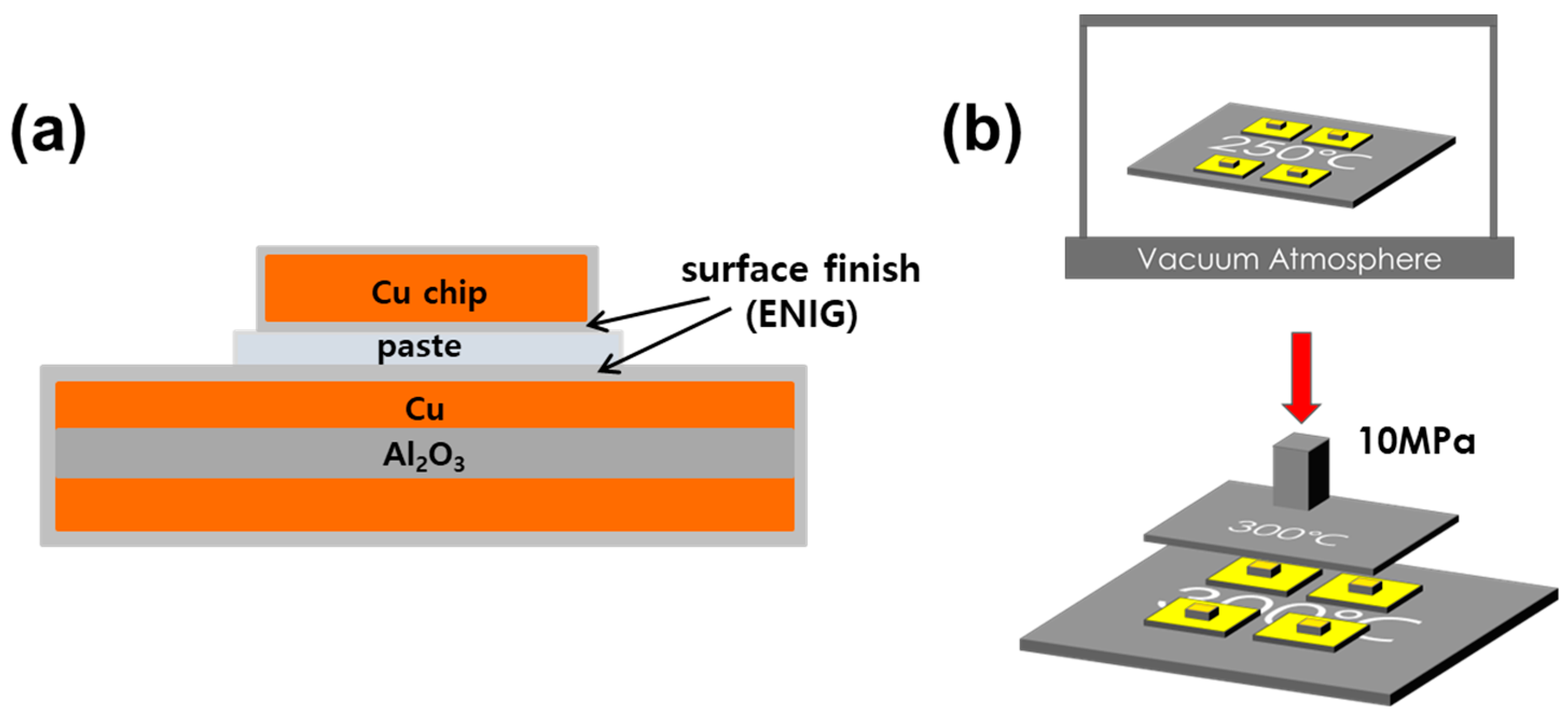
2. Materials and Methods

The composite solder utilized in this experiment was prepared by incorporating 10 wt% of Co powder (Avention (Concord, MA, USA), purity: 99.95%, average diameter: 15 µm) into Sn-3.5Ag solder paste (BBien Tech (Shenzhen, China), particle diameter: 20~38 µm). Throughout the process, a paste mixer (Daehwa Tech (Seongnam-si, Republic of Korea), model: PDM-300) was employed to fabricate the composite solders. The Co content in the composite solder was specified relative to the weight of 100 g of Sn-3.5Ag solder paste, and the solder composition was denoted as Sn-3.5Ag-10.0Co after the cobalt weight ratio within the solder alloy. Mixing was conducted twice for 1 min each at a revolution speed of 800 rpm and a rotation speed of 500 rpm to achieve a homogenous composite solder. The morphology of the solder paste, both pre- and post-mixing with Co particles, is depicted in Figure 1. Here, it is observed that the as-received Co particles are not completely separated from each other; however, post-mixing, it can be confirmed that they are uniformly dispersed among the Sn-3.5Ag solder particles. After the mixing process, the average size of Co particles was measured to be 3.2 ± 1.3 µm.
For the fabrication of specimens utilized in the TLP bonding process, a Cu chip with an electroless nickel-immersion gold (ENIG) surface treatment was bonded to a direct bonded copper (DBC) substrate. The Sn-3.5Ag-10.0Co composite solder, prepared as described above, was screen printed to a thickness of 30 µm onto the substrate. Subsequently, the Cu chip and DBC substrate were joined using a precision die joining device (Tresky AG (Thalwil, Switzerland), model: T-3000-FC3) to form the desired specimen configuration, as depicted in Figure 2. In the TLP bonding process, the specimens underwent initial heating at 250 °C in a vacuum atmosphere for 1 min, followed by a secondary heating stage at 300 °C under a bonding pressure of 10 MPa for durations of 1 h, 2 h, and 3 h. For comparison, the specimens bonded with Sn-3.5Ag paste were also prepared through the TLP bonding process. The specimens were produced through the same TLP bonding process, except that the secondary heating pressure was applied at 3 MPa.
For the cross-sectional analysis of each sample, the specimens were mounted using epoxy material, followed by polishing using silicon carbide (SiC) papers ranging from 180 to 2000 grit and 1µm diamond suspension. Subsequently, etching was performed using a solution comprising 95.0% ethanol, 4.0% nitric acid (HNO3), and 1.0% hydrochloric acid (HCl) by volume. A polished specimen was then obtained.
Compositional analysis and microstructure observation were conducted using a field emission scanning electron microscope (FE-SEM) equipped with electron dispersive X-ray spectroscopy (EDS) capabilities. To assess the shear strength of the joints, a shear test was conducted at a rate of 200 µm/s using a die shear tester (Dage (Stamford, CT, USA), model: BT 4000). After the shear test, X-ray diffraction (XRD) analysis was performed on the Cu chip side of the specimen to analyze the phase of IMCs present on the fracture surfaces.

3. Results

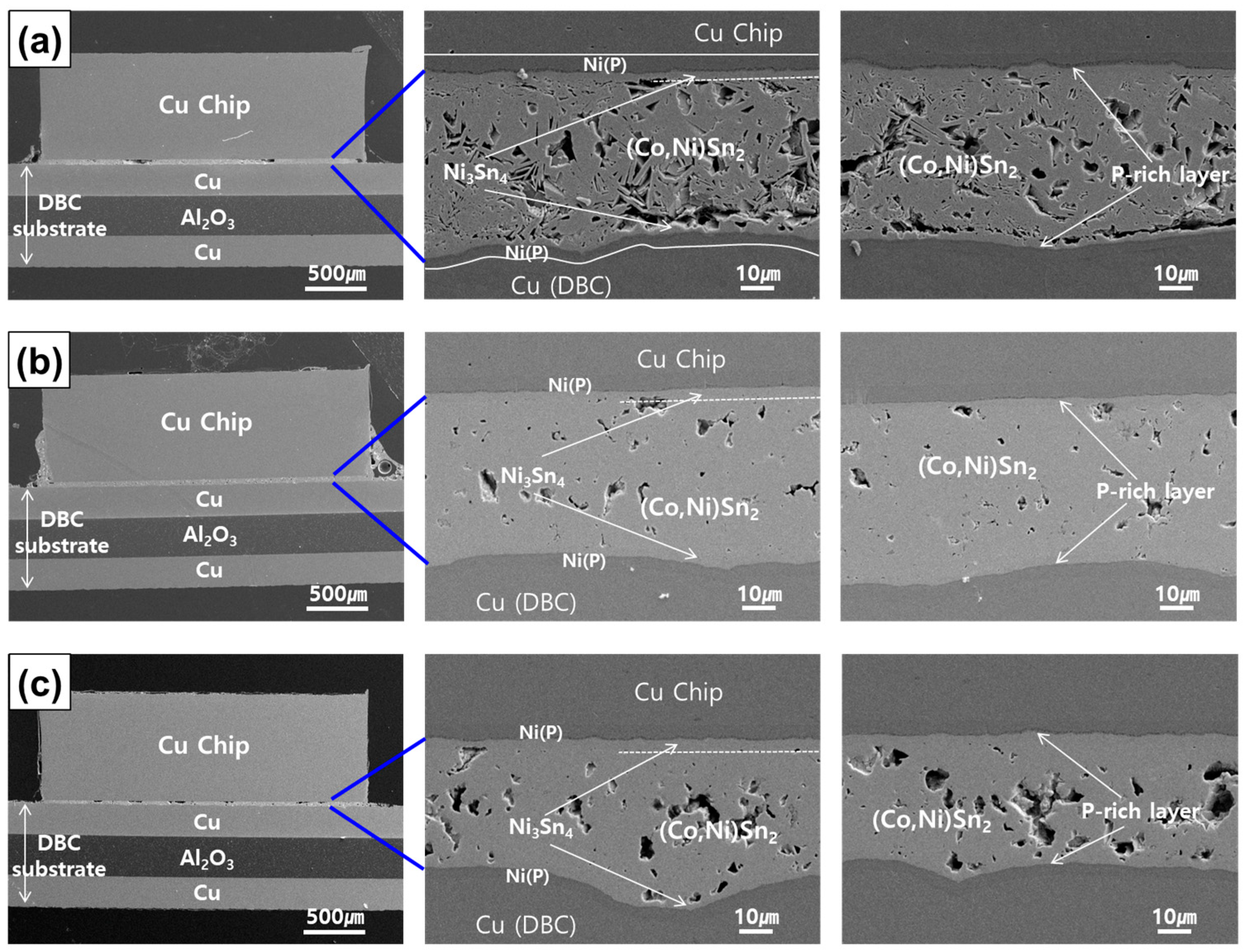
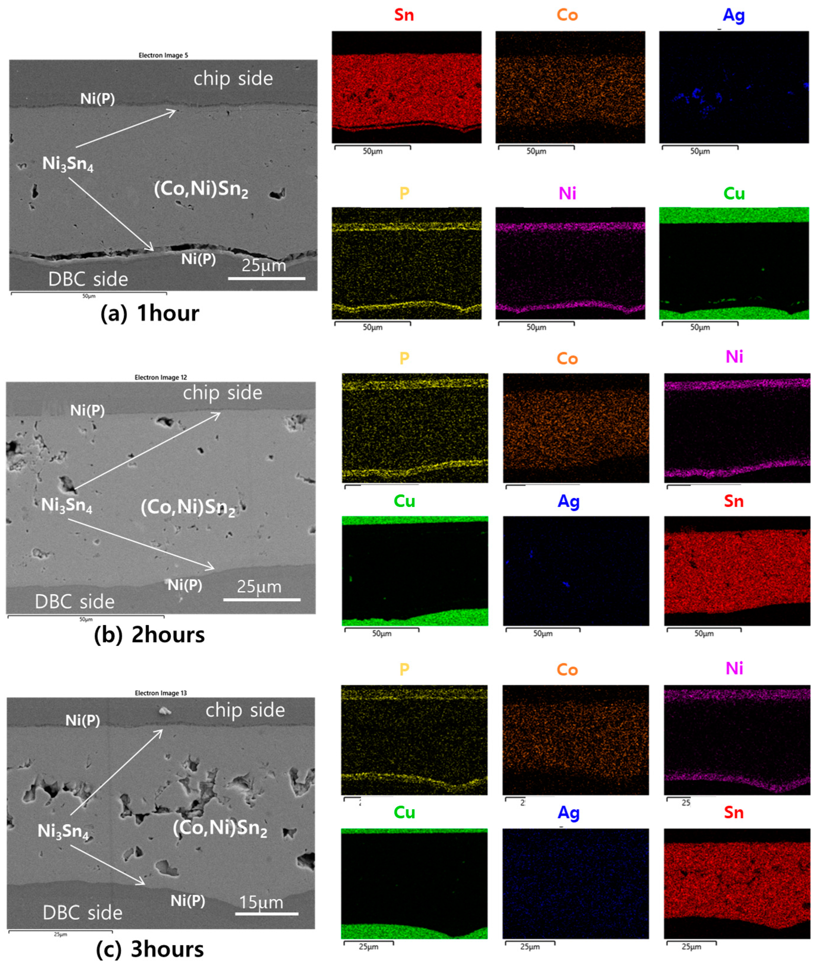
3.1. Phase and Microsturture Evolution during the TLP Bonding Process

After TLP bonding using Sn-3.5Ag-10.0Co solder paste, applied to Cu chips and DBC substrates with ENIG surface treatment, cross-sections of specimens and the bonded joints were as they are depicted in Figure 3. Under bonding conditions of 300 °C and 10 MPa for over an hour, following a 1 min heat treatment at 250 °C, two types of IMCs were observed at the joints of all specimens. On the electroless Ni(P) surface, the Ni3Sn4 phase was observed, while the (Co,Ni)Sn2 phase was prevalent throughout the rest of the joint area. Additionally, a thin P-rich layer appeared dark between the Ni3Sn4 IMC and the electroless Ni(P) remaining after reaction [31,32]. Although the observed phases were consistent across specimens with varying bonding times, the microstructure of the joints varied with bonding duration.
After one hour of TLP bonding, the Sn-3.5Ag-10.0Co paste predominantly transformed into IMCs, yet numerous voids were present between the formed IMCs, particularly between (Co,Ni)Sn2 and Ni3Sn4. Therefore, although phase transformation was nearly complete after one hour of bonding, the joint did not consolidate into a dense mass but remained somewhat fragmented. After two hours of bonding, voids significantly decreased, with (Co,Ni)Sn2 and Ni3Sn4 IMCs being fully interconnected, making it difficult to discern their interfaces. After three hours of bonding, an increase in joint density was observed, accompanied by a reduction in joint thickness. However, a phenomenon where voids congregated towards the center of the joint was observed. These microstructural changes are closely related to the mechanical reliability of TLP-bonded specimens, which is elaborated on in the following section.
Given the absence of prior reports on TLP bonding utilizing Co-added lead-free solders, EDX composition analysis was conducted to precisely assess the IMCs generated on the bonding interfaces. Figure 4 and Figure 5 present the results of line scan and area scan of the TLP joint interfaces, respectively. It was established that Ni3Sn4 IMC typically forms on the surface of the electroless Ni(P) layer following soldering processes involving Sn-based solders [31,32,33,34]. However, in this experiment, discerning the composition of Ni3Sn4 phase is challenging due to its minimal thickness within 2 h of bonding. Nonetheless, after 3 h of bonding, it can be verified that the IMC composition comprises approximately 43 at% Ni and 57 at% Sn, as depicted in Figure 4c. Consequently, it can be inferred that Ni3Sn4 is present. Meanwhile, the majority of the joints are identified as the CoSn2 phase, with trace amounts of Ni indicating the presence of (Co,Ni)Sn2 phase, precisely. Additionally, the formation of Ag3Sn is expected to be at locations where elevated levels of Ag are sporadically detected [35,36,37].
The EDX area mapping results in Figure 5 reaffirm the composition of the joint as consisting of Cu/Ni(P)/Ni3Sn4/(Co,Ni)Sn2 layers. From the Sn and Ni regions depicted in Figure 5a, it is evident that Ni3Sn4 forms on the Ni(P) surface, distinctly separate from the (Co,Ni)Sn2 layer at the bottom of the joint. Referring to the SEM cross-sectional images provided on the left-hand side of Figure 4 and Figure 5, it is observed that after 1 h of TLP bonding, the joint remains incompletely sintered, with the (Co,Ni)Sn2 and Ni3Sn4 IMCs separated. Complete densification occurs after 2 h of bonding, albeit with sporadic voids present. Subsequently, after 3 h, these voids aggregate towards the center of the joint, exhibiting cohesive structures. These observations are consistent with the findings presented in Figure 3.
The formation of IMC during the interaction between liquid Sn and Co is known to be temperature dependent. Wang et al. [38] investigated liquid-state Sn/Co interfacial reactions across temperatures ranging from 240 °C to 340 °C. Below 327 °C, a single uniform CoSn3 layer was observed at the interface. However, as the temperature surpassed 327 °C, the reaction product transitioned to the CoSn2 phase. In contrast to the rapid growth of CoSn3, the CoSn2 layer exhibited thin and irregular growth patterns. Odashima et al. [39] conducted experimental examinations on the kinetics of reactive diffusion between solid Co and liquid Sn using semi-infinite Co/Sn diffusion couples prepared via an isothermal bonding technique. At 310 °C, the overall growth rate was notably slower compared to lower annealing temperatures. This was attributed to the identification of two compounds (CoSn2 and CoSn3) at the interface, whereas only CoSn3 formed within the range of 250 °C to 290 °C.
Furthermore, it has been documented that the IMC formed varies with the heat treatment temperature even when Co is present in lead-free solder. Gao et al. [40] investigated the Sn–3.0Ag–0.5Cu–0.5Co solder alloy, subjecting it to heating up to 300 °C or 400 °C followed by cooling to room temperature. Regardless of the cooling rate, only the CoSn3 phase formed in the solder alloy when heated to 300 °C. However, during solidification from 400 °C, the CoSn2 + CoSn3 cascade structures were observed following slow furnace cooling due to the peritectic reaction. Based on these reports, it can be inferred that the formation of the CoSn2 phase occurs at reaction temperatures exceeding 300 °C. In this study, following reaction at 300 °C and 10 MPa for over 1 h, the entire Sn-3.5Ag-10.0Co solder underwent a transformation into the CoSn2 phase. This outcome aligns with the minimum temperature at which CoSn2 formation was observed during liquid Sn and Co reaction, which may be attributed to the prolonged reaction duration under elevated pressure conditions.

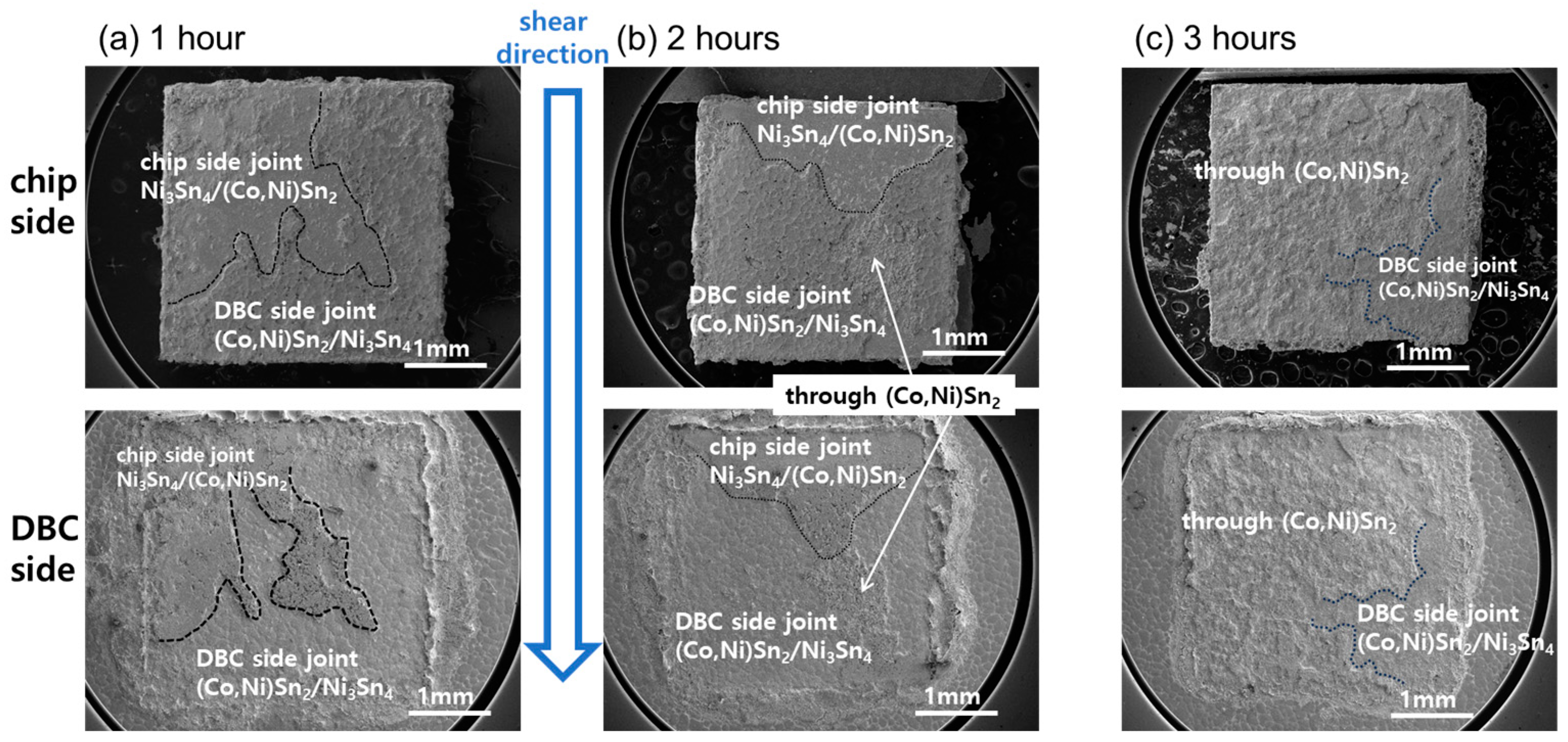
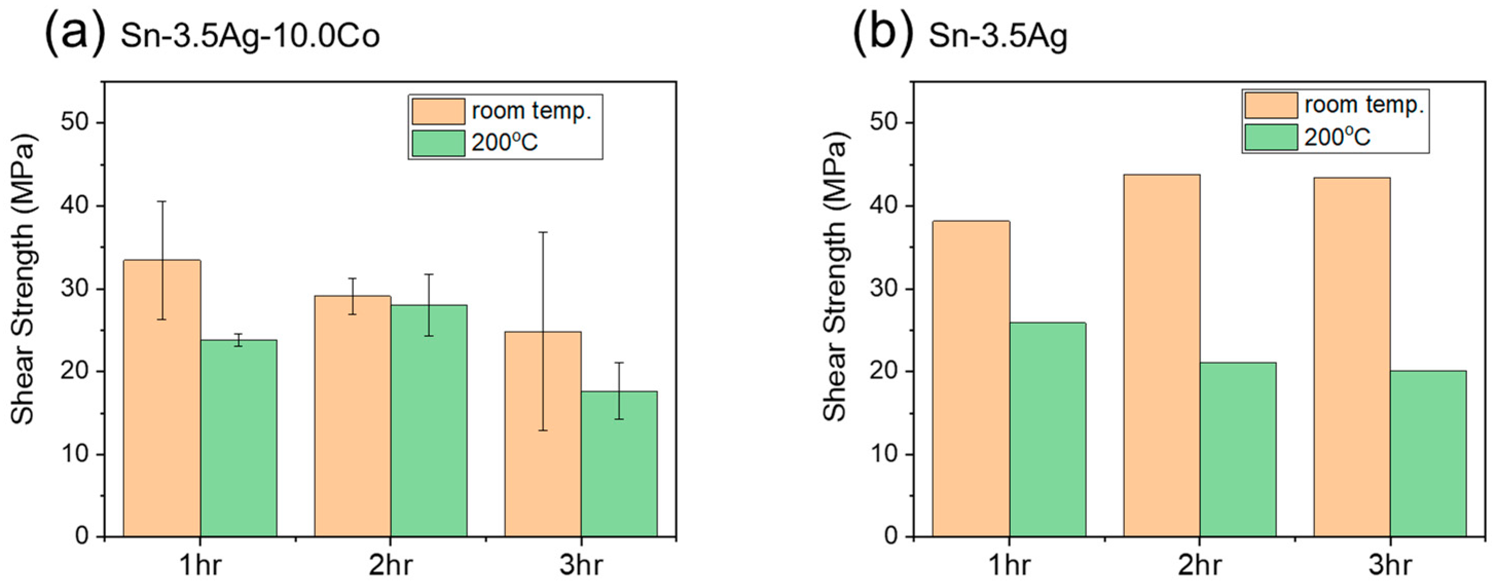
3.2. Shear Test Results of TLP-Bonded Specimens

A shear test was conducted on the specimens following completion of TLP bonding, and the fracture surfaces are presented in Figure 6. As discussed in the preceding section concerning the microstructure post-TLP bonding, solder sintering remains incomplete after 1 h of bonding, with numerous cracks observed between Ni3Sn4 and (Co,Ni)Sn2 IMCs on both the chip and DBC sides. Consequently, during shear testing, fractures frequently occur between these IMCs, resulting in a smooth fracture surface which is characteristic of brittle fracture. Figure 6b illustrates that this type of failure persists even after 2 h of bonding. Following 3 h of bonding, voids aggregated significantly in the joint’s center, leading to destruction not only between the aforementioned IMCs but also along the voids within the (Co,Ni)Sn2 layer. The shear test was conducted at room temperature and 200 °C, but there was no significant difference in the failure locus, so only the failure surfaces in the room temperature test are presented here.
Figure 7a presents the measured shear strength obtained from the shear test conducted on the TLP bonding specimens with Sn-3.5Ag-10.0Co composite solder. The tests were performed at room temperature (orange) and at 200 °C (green). For comparison, some TLP-bonded specimens were also fabricated using Sn-3.5Ag solder without the addition of Co, and the measured bond strength is depicted in Figure 7b.
The bonding strength of specimens utilizing Sn-3.5Ag-10.0Co composite solder ranged approximately at 30 ± 5 MPa at room temperature. At 200 °C, both 1 h and 3 h bonded specimens, exhibiting a relatively high void content within the joints, resulted in a decrease in shear strength. Conversely, the 2 h bonded specimen, characterized by a dense internal structure and a reduced number of voids distributed throughout, demonstrated stable strength, even at elevated temperatures. Notably, the shear strength significantly decreased at high temperatures in specimens bonded with Sn-3.5Ag, a phenomenon that is elaborated upon in the subsequent section.

4. Discussion

4.1. Correlation between Microstructure and Mechanical Reliability

The failure loci of Sn-3.5Ag-10.0Co TLP-bonded specimens are outlined in the schematic diagram provided in Figure 8. In the 1 h TLP-bonded specimen, crack propagation was observed at the interface between Ni3Sn4 and (Co,Ni)Sn2, as well as within the structurally loose interior of the (Co,Ni)Sn2 layer. Notably, areas of unbonded and separated material were already present between Ni3Sn4 and (Co,Ni)Sn2 before the shear test. In the 2 h bonded specimen, failure occurred at the interface of Ni3Sn4 and (Co,Ni)Sn2, both on the chip and DBC sides. In the 3 h bonded specimen, failure was observed along the internal voids within the (Co,Ni)Sn2 IMC layer, partly involving the interface of Ni3Sn4/(Co,Ni)Sn2.
The operational temperature of power devices in electric vehicles can reach approximately 280 °C, necessitating robust high-temperature reliability of solder joints. It is crucial to avoid the formation of pure Sn in these joints, as it weakens bonding strength at elevated temperatures and eventually liquefies at 232 °C. Previous studies [38,39,40] have identified that at low temperatures below 300 °C, the first forming phase in Sn and Co reactions is CoSn3. However, referring to the Sn-Co phase equilibrium diagram [41,42], it is evident that the melting point of CoSn3, at 345 °C, is insufficiently high for our purposes. At 280 °C, the homologous temperature (T/Tm) for CoSn3 is approximately 0.9, indicating its incapability to withstand the high-temperature demands of power device junctions.
Consequently, the formation of CoSn2 (melting point 570 °C), CoSn (965 °C), or Co3Sn2 (1181 °C) phases, rather than CoSn3, is imperative in solder joints for power devices. In this study, through meticulous adjustment of bonding time and pressure, we achieved complete transformation of the entire TLP joint into the CoSn2 phase with a bonding time of 1 h. The homologous temperatures of the resulting IMCs formed at the joint are summarized in Table 1. The melting points of Ni3Sn4 and CoSn2 phases were 1071K and 843K, respectively. The shear test conducted at 200 °C, corresponding to 0.44 and 0.56 T/Tm for Ni3Sn4 and CoSn2, respectively, resulted in negligible strength reduction during testing.
In contrast, if pure Sn remained in the solder joint after utilizing Sn-3.5Ag solder paste for joining, ductile fracture occurred through the Sn during the shear test, as illustrated in Figure 9. Under shear stress, substantial plastic deformation took place in Sn, facilitated by dislocation movement. At 200 °C, corresponding to 0.94 T/Tm, a heightened dislocation movement and prominent slip bands were observable. This mechanism led to a significant reduction in shear strength by about half at 200 °C compared to room temperature, as depicted in Figure 7b.
Similar findings are documented in the existing literature. Jeong et al. [43] investigated the temperature’s influence on the shear properties of Sn-3.0Ag-0.5Cu and Sn-58Bi solder joints. For Sn-3.0Ag-0.5Cu solder, escalating temperature led to decreased shear force, increased fracture distance, and diminished fracture energy. Moreover, the fractures predominantly exhibited ductile behavior. Mohammadi et al. [44] observed a decrease in shear strength and an increase in shear strain at failure of Sn-based Sn-0.7Cu-xSiC solder joints with rising test temperatures.

4.2. Void Formation in the TLP Joint Interfaces

The primary cause of void formation in TLP systems typically arises from volume shrinkage during the reaction process [45,46,47,48,49,50]. When two initial reactants combine to form an IMC layer, it often results in a reduction in volume. This phenomenon occurs because the structure and number density of the newly formed IMC can differ from those of the initial reactants. Consequently, the equilibrium condition necessitates a smaller volume for IMC formation than the combined volume of the initial reactants. However, within a confined volume, the formation of IMC induces tensile stress in the joint. If this stress exceeds the material’s threshold for plastic deformation, it leads to discontinuity in the material. In practical terms, this stress relief manifests through the formation of voids.
The volume shrinkage during the formation of Ni3Sn4 and CoSn2 IMCs can be quantified using Equations (1) and (2). Due to the unavailability of precise physical properties for the (Co,Ni)Sn2 phase, the calculations were performed for the CoSn2 phase.
3 Ni + 4 Sn     Ni 3 Sn 4 :   M N i 3 S n 4 ρ N i 3 S n 4 ( 3 M N i ρ N i + 4 M S n ρ S n ) ( 3 M N i ρ N i + 4 M S n ρ S n )
Co + 2 Sn     CoS n 2 :   M C o S n 2 ρ C o S n 2 ( M C o ρ C o + 2 M S n ρ S n ) ( M C o ρ C o + 2 M S n ρ S n )
Here, M and ρ represent the molar mass (atomic weight) and density, respectively. The densities of the Ni3Sn4 and CoSn2 phases are 8.64 and 8.91 g/cm3 [51,52]. According to the calculations, volume shrinkage is anticipated to be −11.3% and −14.9% for the formation of Ni3Sn4 and CoSn2, respectively. The significant volume shrinkage observed during the formation of both IMCs is considered the primary cause of voids at the TLP-bonded joints.
Chuang et al. [46] and Li et al. [47] conducted TLP bonding by depositing solder in a layered structure using electroplating methods, resulting in the formation of IMCs at both interfaces, which grew towards the center, leading to voids only at the interface center. In contrast, in our experiment, using solder paste, voids formed at various points throughout the joint as Sn-3.5Ag particles, and Co particles reacted with each other across the joint. These voids tended to coalesce in the middle over time due to diffusion-driven solid-state reactions during prolonged reaction times.

5. Conclusions

In this investigation, we engineered a novel composite solder composed of Sn-Ag-Co tailored specifically for integration into electric vehicle power modules. Through a meticulously devised two-step joining protocol, we achieved a comprehensive transformation of the solder joint into a robust microstructure characterized by high-melting-point IMCs. The ensuing findings and conclusions are detailed below.
(1)
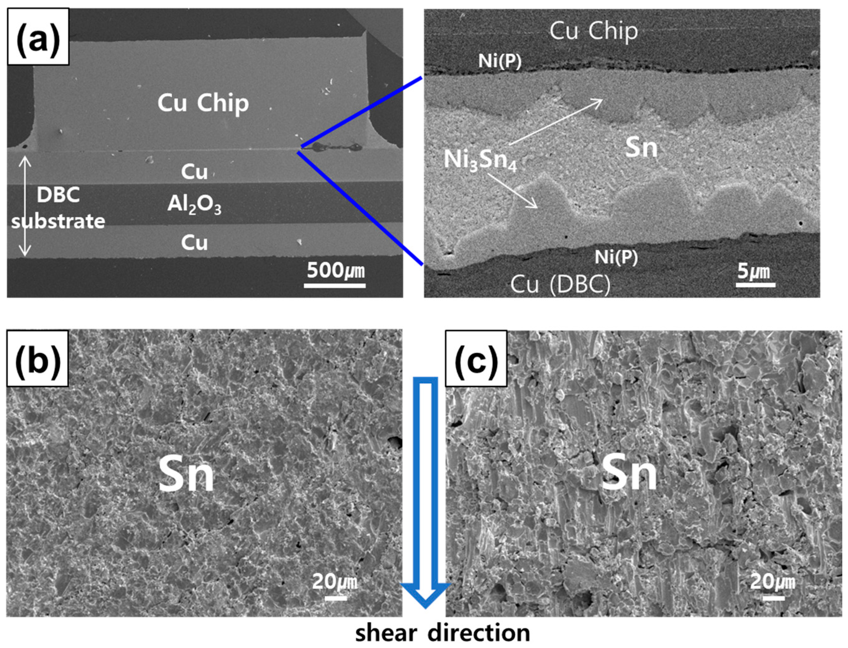
After 1 h of TLP bonding, the Sn-3.5Ag-10.0Co paste transformed into IMCs, but voids persisted between them, particularly between (Co,Ni)Sn2 and Ni3Sn4. Voids significantly reduced after 2 h of bonding, with IMCs fully interconnected. The joint density further increased after 3 h of bonding, but voids tended to accumulate at the joint center.
(2)
Under TLP bonding conditions of 300 °C and 10 MPa, the entire Sn-3.5Ag-10.0Co solder underwent transformation into the high-melting point CoSn2 phase. This result corresponds to the observed minimum temperature required for CoSn2 formation during the reaction between liquid Sn and Co, possibly due to the extended reaction duration under elevated pressure.
(3)
In the 1 h bonded specimen, cracks propagated through the interface of Ni3Sn4 and (Co,Ni)Sn2, exhibiting separation, as well as within the loose interior of the (Co,Ni)Sn2 layer. In the 2 h bonded specimen, failure occurred at the interface of Ni3Sn4 and (Co,Ni)Sn2, present on both the chip and DBC sides. In the 3 h bonded specimen, failure was observed within the internal voids of the (Co,Ni)Sn2 IMC layer, partly involving the Ni3Sn4/(Co,Ni)Sn2 interface.
(4)
When utilizing the engineered Sn-Ag-Co TLP joint, no significant decrease in shear strength was observed, even under the 200 °C shear test. In contrast, the Sn-3.5Ag control specimen exhibited large reduction in shear strength. This decline can be attributed to the fact that the shear test temperature corresponds to 0.94 homologous temperature for the remaining Sn, evident by the presence of numerous shear bands.

Author Contributions

Conceptualization, methodology, writing—original draft, and funding acquisition, Y.S.; investigation, methodology, and data curation, B.K.; investigation, data curation, and visualization, G.C.; methodology, writing—review editing, and formal analysis, Y.-H.K. and Y.S. All authors have read and agreed to the published version of the manuscript.

Funding

This study was supported by a research fund from Chosun University, 2023.

Data Availability Statement

Data are contained within the article.

Conflicts of Interest

The authors declare no conflicts of interest.

References

  1. Chen, X.; Wang, Q.; Huang, X.; Muhammad, A.; Paramane, A.; Ren, N. Enhancement of electrical properties by including nano-aluminum nitride to micro-silicon carbide/silicone elastomer composites for potential power module packaging applications. J. Mater. Sci. Mater. Electron. 2022, 33, 18768–18785. [Google Scholar] [CrossRef]
  2. Zhang, Y.; Nee, H.P.; Hammam, T.; Belov, I.; Ranstad, P.; Bakowski, M. Multiphysics characterization of a novel SiC power module. IEEE Trans. Compon. Packag. Manuf. Technol. 2018, 9, 489–501. [Google Scholar] [CrossRef]
  3. He, S.; Que, L.; Lv, J.; Ang, S.S. Silicon carbide power electronic module packaging. In Proceedings of the 2015 16th International Conference on Electronic Packaging Technology (ICEPT), Changsha, China, 11–14 August 2015; pp. 483–486. [Google Scholar]
  4. Khazaka, R.; Mendizabal, L.; Henry, D.; Hanna, R. Survey of high-temperature reliability of power electronics packaging components. IEEE Trans. Power Electron. 2014, 30, 2456–2464. [Google Scholar] [CrossRef]
  5. Syed-Khaja, A. Diffusion Soldering for the High-Temperature Packaging of Power Electronics; FAU University Press: Boca Raton, FL, USA, 2018. [Google Scholar]
  6. Jung, D.H.; Sharma, A.; Mayer, M.; Jung, J.P. A review on recent advances in transient liquid phase (TLP) bonding for thermoelectric power module. Rev. Adv. Mater. Sci. 2018, 53, 147–160. [Google Scholar] [CrossRef]
  7. Kang, H.; Sharma, A.; Jung, J.P. Recent progress in transient liquid phase and wire bonding technologies for power electronics. Metals 2020, 10, 934. [Google Scholar] [CrossRef]
  8. Liu, Y.; Joshi, S.N.; Dede, E.M. Novel transient liquid phase bonding for high-temperature automotive power electronics systems. J. Electron. Packag. 2020, 142, 011003. [Google Scholar] [CrossRef]
  9. Baek, S.; Jeong, G.W.; Son, J.H.; Kim, M.S.; Lee, H.B.R.; Kim, J.; Ko, Y.H. Interfacial reactions and mechanical properties of transient liquid-phase bonding joints in Cu/Sn/Ni (P) and Ni/Sn/(OSP) Cu structures for power modules. J. Mater. Sci. Mater. Electron. 2021, 32, 3324–3333. [Google Scholar] [CrossRef]
  10. Yoon, S.W.; Glover, M.D.; Shiozaki, K. Nickel–tin transient liquid phase bonding toward high-temperature operational power electronics in electrified vehicles. IEEE Trans. Power Electron. 2012, 28, 2448–2456. [Google Scholar] [CrossRef]
  11. Lee, B.S.; Hyun, S.K.; Yoon, J.W. Cu–Sn and Ni–Sn transient liquid phase bonding for die-attach technology applications in high-temperature power electronics packaging. J. Mater. Sci. Mater. Electron. 2017, 28, 7827–7833. [Google Scholar] [CrossRef]
  12. Lis, A.; Kicin, S.; Brem, F.; Leinenbach, C. Thermal stress assessment for transient liquid-phase bonded Si chips in high-power modules using experimental and numerical methods. J. Electron. Mater. 2017, 46, 729–741. [Google Scholar] [CrossRef]
  13. Pahinkar, D.G.; Puckett, W.; Graham, S.; Boteler, L.; Ibitayo, D.; Narumanchi, S.; Major, J. Transient liquid phase bonding of AlN to AlSiC for durable power electronic packages. Adv. Eng. Mater. 2018, 20, 1800039. [Google Scholar] [CrossRef]
  14. Chidambaram, V.; Hattel, J.H. High-temperature lead-free solder alternatives. Microelectron. Eng. 2011, 88, 981–989. [Google Scholar] [CrossRef]
  15. Sharif, A.; Gan, C.L.; Chen, Z. Transient liquid phase Ag-based solder technology for high-temperature packaging applications. J. Alloys Compd. 2014, 587, 365–368. [Google Scholar] [CrossRef]
  16. Fujino, M.; Narusawa, H.; Kuramochi, Y.; Higurashi, E.; Suga, T.; Shiratori, T.; Mizukoshi, M. Transient liquid-phase sintering using tin and silver powder mixture for die bonding. In Proceedings of the International Conference on Solid State Devices and Materials, Sapporo, Japan, 27–30 September 2015; The Japan Society of Applied Physics: Tokyo, Japan; pp. 60–61. [Google Scholar]
  17. Bao, Y.D.; Wu, A.P.; Shao, H.K.; Zhao, Y.; Liu, L.; Zou, G.S. Microstructural evolution and mechanical reliability of transient liquid phase sintered joint during thermal aging. J. Mater. Sci. 2019, 54, 765–776. [Google Scholar] [CrossRef]
  18. Saud, N.; Said, R.M. Transient liquid phase bonding for solder-a short review. IOP Conf. Ser. Mater. Sci. Eng. 2019, 701, 012050. [Google Scholar] [CrossRef]
  19. Greve, H.; Moeini, S.A.; McCluskey, P.; Joshi, S. Prediction and mitigation of vertical cracking in high-temperature transient liquid phase sintered joints by thermomechanical simulation. J. Electron. Packag. 2018, 140, 020903. [Google Scholar] [CrossRef]
  20. Lang, F.; Yamaguchi, H.; Nakagawa, H.; Sato, H. Thermally stable bonding of SiC devices with ceramic substrates: Transient liquid phase sintering using Cu/Sn powders. J. Electrochem. Soc. 2013, 160, 315–319. [Google Scholar] [CrossRef]
  21. Nishikawa, H.; Komatsu, A.; Takemoto, T. Interfacial reaction between Sn–Ag–Co solder and metals. Mater. Trans. 2005, 46, 2394–2399. [Google Scholar] [CrossRef]
  22. Nishikawa, H.; Komatsu, A.; Takemoto, T. Effect of Ni or Co addition to Sn-Ag solder on microstructure and joint strength at interface. Mater. Trans. 2008, 49, 1518–1523. [Google Scholar] [CrossRef]
  23. Tay, S.L.; Haseeb, A.S.M.A.; Johan, M.R. Effect of addition Cobalt nanoparticles on Sn-Ag-Cu lead-free solder. In Proceedings of the 2010 12th Electronics Packaging Technology Conference, Singapore, 8–10 December 2010; pp. 433–436. [Google Scholar]
  24. Lee, J.S.; Chu, K.M.; Patzelt, R.; Manessis, D.; Ostmann, A.; Jeon, D.Y. Effects of Co addition in eutectic Sn–3.5 Ag solder on shear strength and microstructural development. Microelectron. Eng. 2008, 85, 1577–1583. [Google Scholar] [CrossRef]
  25. Nishikawa, H.; Komatsu, A.; Takemoto, T. Morphology and pull strength of Sn-Ag(-Co) solder joint with copper pad. J. Electron. Mater. 2007, 36, 1137–1143. [Google Scholar] [CrossRef]
  26. Yakymovych, A.; Plevachuk, Y.; Švec, P.; Janičkovič, D.; Šebo, P.; Beronska, N.; Ipser, H. Nanocomposite SAC solders: Morphology, electrical and mechanical properties of Sn–3.8 Ag–0.7 Cu solders by adding Co nanoparticles. J. Mater. Sci. Mater. Electron. 2017, 28, 10965–10973. [Google Scholar] [CrossRef]
  27. Anderson, I.E.; Foley, J.C.; Cook, B.A.; Harringa, J.; Terpstra, R.L.; Unal, O. Alloying effects in near-eutectic Sn-Ag-Cu solder alloys for improved microstructural stability. J. Electron. Mater. 2001, 30, 1050–1059. [Google Scholar] [CrossRef]
  28. Kim, D.; Nagao, S.; Chen, C.; Wakasugi, N.; Yamamoto, Y.; Suetake, A.; Takemasa, T.; Sugahara, T.; Suganuma, K. Online thermal resistance and reliability characteristic monitoring of power modules with Ag sinter joining and Pb, Pb-free solders during power cycling test by SiC TEG chip. IEEE Trans. Power Electron. 2020, 36, 4977–4990. [Google Scholar] [CrossRef]
  29. Wang, M.; Mei, Y.H.; Jin, J.; Chen, S.; Li, X.; Lu, G.Q. Pressureless sintered-silver die-attach at 180 °C for power electronics packaging. IEEE Trans. Power Electron. 2021, 36, 12141–12145. [Google Scholar] [CrossRef]
  30. Yin, L.; Yang, F.; Bao, X.; Xue, W.; Du, Z.; Wang, X.; Cheng, J.; Ji, H.; Sui, J.; Liu, X.; et al. Low-temperature sintering of Ag nanoparticles for high-performance thermoelectric module design. Nat. Energy 2023, 8, 665–674. [Google Scholar] [CrossRef]
  31. Alam, M.O.; Chan, Y.C.; Hung, K.C. Reliability study of the electroless Ni–P layer against solder alloy. Microelectron. Reliab. 2002, 42, 1065–1073. [Google Scholar] [CrossRef]
  32. Yoon, J.W.; Park, J.H.; Shur, C.C.; Jung, S.B. Characteristic evaluation of electroless nickel–phosphorus deposits with different phosphorus contents. Microelectron. Eng. 2007, 84, 2552–2557. [Google Scholar] [CrossRef]
  33. Liu, P.L.; Xu, Z.; Shang, J.K. Thermal stability of electroless-nickel/solder interface: Part A. Interfacial chemistry and microstructure. Metall. Mater. Trans. A 2000, 31, 2857–2866. [Google Scholar] [CrossRef]
  34. Sohn, Y.C.; Yu, J.; Kang, S.K.; Shih, D.Y.; Choi, W.K. Effects of phosphorus content on the reaction of electroless Ni-P with Sn and crystallization of Ni-P. J. Electron. Mater. 2004, 33, 790–795. [Google Scholar] [CrossRef]
  35. Qi, L.; Huang, J.; Zhao, X.; Zhang, H. Effect of thermal-shearing cycling on Ag3Sn microstructural coarsening in SnAgCu solder. J. Alloys Compd. 2009, 469, 102–107. [Google Scholar] [CrossRef]
  36. Cui, Y.; Xian, J.W.; Zois, A.; Marquardt, K.; Yasuda, H.; Gourlay, C.M. Nucleation and growth of Ag3Sn in Sn-Ag and Sn-Ag-Cu solder alloys. Acta Mater. 2023, 249, 118831. [Google Scholar] [CrossRef]
  37. Shen, J.; Chan, Y.C.; Liu, S.Y. Growth mechanism of bulk Ag3Sn intermetallic compounds in Sn–Ag solder during solidification. Intermetallics 2008, 16, 1142–1148. [Google Scholar] [CrossRef]
  38. Wang, C.H.; Kuo, C.Y.; Huang, S.E.; Li, P.Y. Temperature effects on liquid-state Sn/Co interfacial reactions. Intermetallics 2013, 32, 57–63. [Google Scholar] [CrossRef]
  39. Odashima, N.; O, M.; Kajihara, M. Formation of intermetallic compounds and microstructure evolution due to isothermal reactive diffusion at the interface between solid Co and liquid Sn. J. Electron. Mater. 2020, 49, 1568–1576. [Google Scholar] [CrossRef]
  40. Gao, F.; Cheng, F.; Nishikawa, H.; Takemoto, T. Characterization of Co–Sn intermetallic compounds in Sn–3.0 Ag–0.5 Cu–0.5 Co lead-free solder alloy. Mater. Lett. 2008, 62, 2257–2259. [Google Scholar] [CrossRef]
  41. Vassilev, G.P.; Lilova, K.I.; Gachon, J.C. Calorimetric and phase diagram studies of the Co-Sn system. Intermetallics 2007, 15, 1156–1162. [Google Scholar] [CrossRef]
  42. Baheti, V.A. Phase evolutions and growth kinetics in the Co–Sn system. SN Appl. Sci. 2019, 1, 185. [Google Scholar] [CrossRef]
  43. Jeong, M.S.; Lee, D.H.; Yoon, J.W. Effect of temperature on shear properties of Sn-3.0 Ag-0.5 Cu and Sn-58Bi solder joints. J. Alloys Compd. 2022, 903, 163987. [Google Scholar] [CrossRef]
  44. Mohammadi, A.; Mahmudi, R. Elevated-temperature mechanical properties of lead-free Sn-0.7Cu-xSiC nanocomposite solders. J. Electron. Mater. 2018, 47, 1721–1729. [Google Scholar] [CrossRef]
  45. Hang, C.; Tian, Y.; Zhang, R.; Yang, D. Phase transformation and grain orientation of Cu–Sn intermetallic compounds during low temperature bonding process. J. Mater. Sci. Mater. Electron. 2013, 24, 3905–3913. [Google Scholar] [CrossRef]
  46. Chuang, H.Y.; Yu, J.J.; Kuo, M.S.; Tong, H.M.; Kao, C.R. Elimination of voids in reactions between Ni and Sn: A novel effect of silver. Scr. Mater. 2012, 66, 171–174. [Google Scholar] [CrossRef]
  47. Li, C.C.; Chung, C.K.; Shih, W.L.; Kao, C.R. Volume shrinkage induced by interfacial reaction in micro-Ni/Sn/Ni joints. Metall. Mater. Trans. A 2014, 45, 2343–2346. [Google Scholar] [CrossRef]
  48. Lin, S.K.; Cho, C.L.; Chang, H.M. Interfacial reactions in Cu/Ga and Cu/Ga/Cu couples. J. Electron. Mater. 2014, 43, 204–211. [Google Scholar] [CrossRef]
  49. Mokhtari, O.; Nishikawa, H. The shear strength of transient liquid phase bonded Sn–Bi solder joint with added Cu particles. Adv. Powd. Technol. 2016, 27, 1000–1005. [Google Scholar] [CrossRef]
  50. Shao, H.; Wu, A.; Bao, Y.; Zhao, Y.; Zou, G. Microstructure characterization and mechanical behavior for Ag3Sn joint produced by foil-based TLP bonding in air atmosphere. Mater. Sci. Eng. A 2017, 680, 221–231. [Google Scholar] [CrossRef]
  51. Villars, P. (Ed.) Ni3Sn4 Crystal Structure. In Pauling File in: Inorganic Solid Phases; SpringerMaterials (online database); Springer: Berlin/Heidelberg, Germany, 2023; Available online: https://materials.springer.com/isp/crystallographic/docs/sd_0528976 (accessed on 1 May 2024).
  52. Armbrüster, M.; Schmidt, M.; Cardoso-Gil, R.; Borrmann, H.; Grin, Y. Crystal structures of iron distannide, FeSn2, and cobalt distannide, CoSn2. Z. Krist.-New Cryst. Struct. 2007, 222, 83–84. [Google Scholar] [CrossRef]
Figure 1. Morphologies of (a) as-received Co powder and (b) Sn-3.5Ag-10.0Co paste after planetary mixing; (c) magnified view of (b).
Electronics 13 02173 g001
Figure 2. Schematic for (a) a specimen used for TLP bonding experiment and (b) the TLP bonding process.
Electronics 13 02173 g002
Figure 3. Cross-sectional micrographs of TLP-bonded specimens after secondary heating at 300 °C for (a) 1 h, (b) 2 h, and (c) 3 h.
Electronics 13 02173 g003
Figure 4. Compositional analysis results using EDX line scan of TLP bonded specimens after secondary heating at 300 °C for (a) 1 h, (b) 2 h, and (c) 3 h.
Electronics 13 02173 g004
Figure 5. Compositional analysis results using EDX area scan of TLP bonded specimens after secondary heating at 300 °C for (a) 1 h, (b) 2 h, and (c) 3 h.
Electronics 13 02173 g005
Figure 6. Fractured surfaces of the TLP-bonded specimens after shear test. Bonding duration: (a) 1 h, (b) 2 h, and (c) 3 h.
Electronics 13 02173 g006
Figure 7. Measured shear strength for the TLP-bonded specimens at room temperature (orange) and at 200 °C (green). TLP bonding solder: (a) Sn-3.5Ag-10.0Co and (b) Sn-3.5Ag.
Electronics 13 02173 g007
Figure 8. Schematic diagrams showing failure loci of Sn-3.5Ag-10.0Co TLP-bonded specimens during shear test. Bonding duration: (a) 1 h, (b) 2 h, and (c) 3 h.
Electronics 13 02173 g008
Figure 9. (a) Cross-sectional SEM micrographs showing Sn-3.5Ag TLP-bonded interface (after 2 h). Fractured surfaces of Sn-3.5Ag TLP specimens after shear test at (b) room temperature and (c) 200 °C.
Electronics 13 02173 g009
Table 1. Homologous temperatures of Sn and the IMCs formed at TLP bonding joints.
Ni3Sn4CoSn2Sn
Melting temp. (K)1071843505
Test temp. 1 (K)
Homologous temp. (T/Tm)
293
0.27
293
0.35
293
0.58
Test temp. 2 (K)
Homologous temp. (T/Tm)
473
0.44
473
0.56
473
0.94
Disclaimer/Publisher’s Note: The statements, opinions and data contained in all publications are solely those of the individual author(s) and contributor(s) and not of MDPI and/or the editor(s). MDPI and/or the editor(s) disclaim responsibility for any injury to people or property resulting from any ideas, methods, instructions or products referred to in the content.

