
A Compact C-Band Multiple-Input Multiple-Output Circular Microstrip Patch Antenna Array with Octagonal Slotted Ground Plane and Neutralization Line for Improved Port Isolation in 5G Handheld Devices

Abstract
:1. Introduction
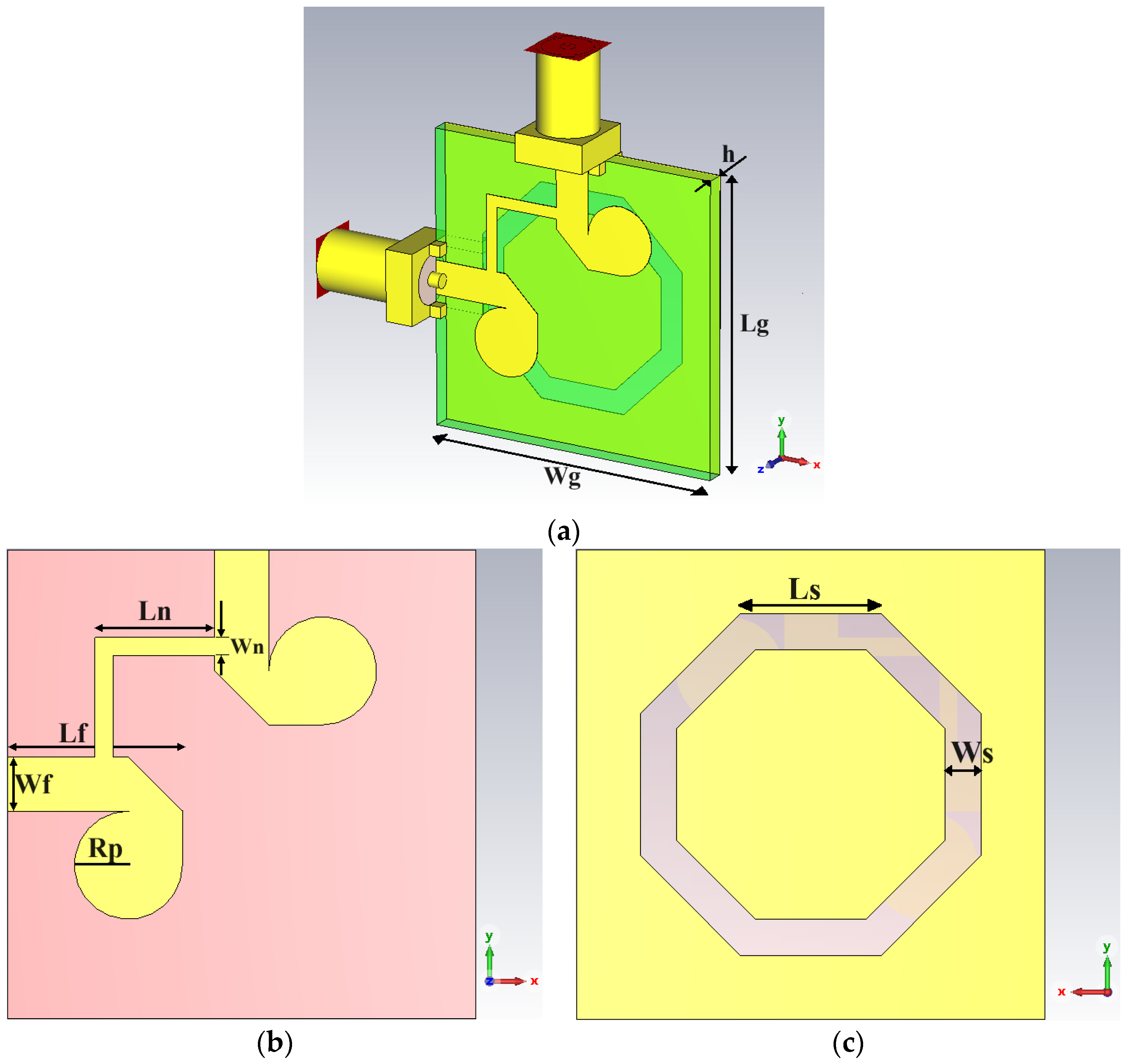
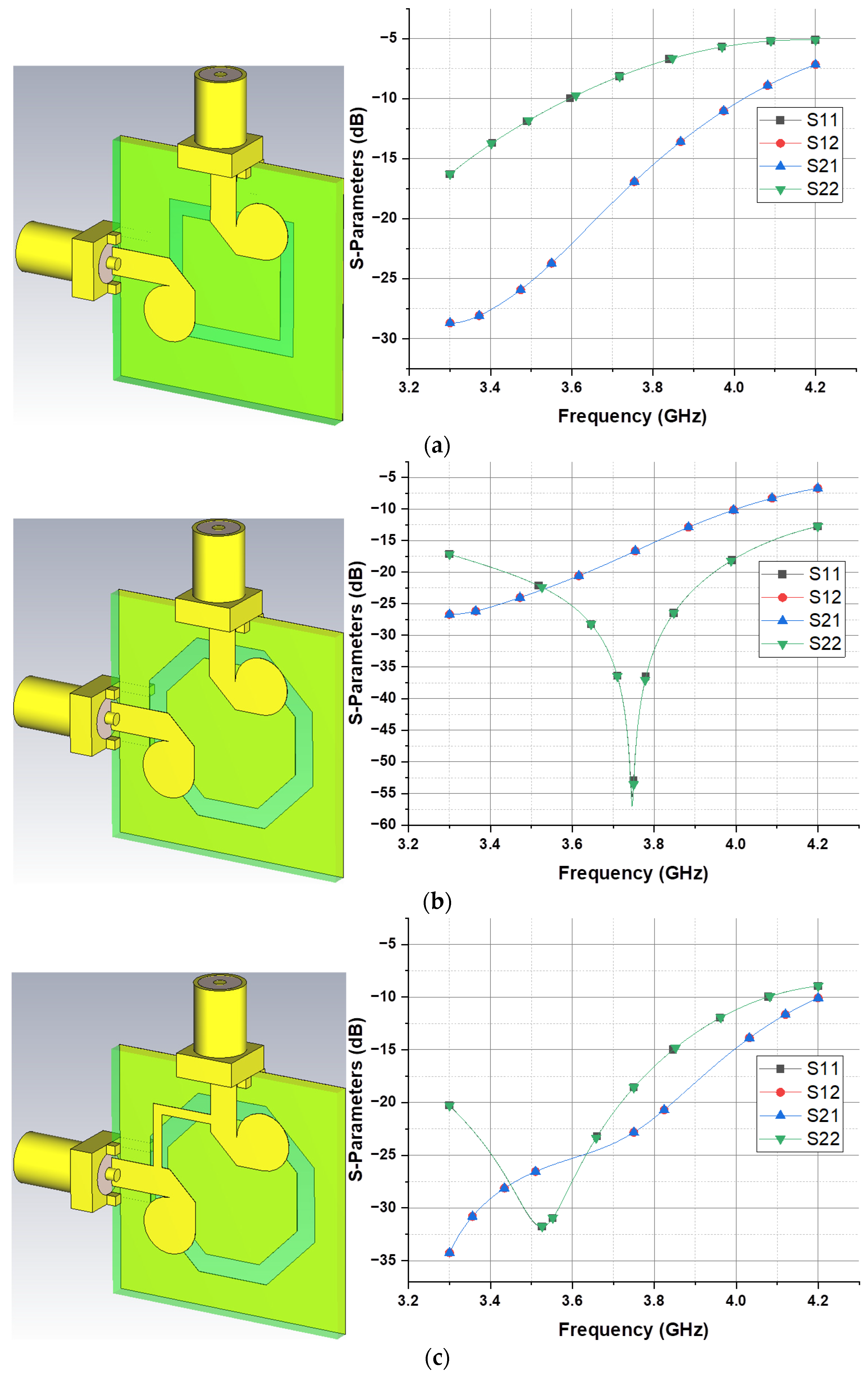
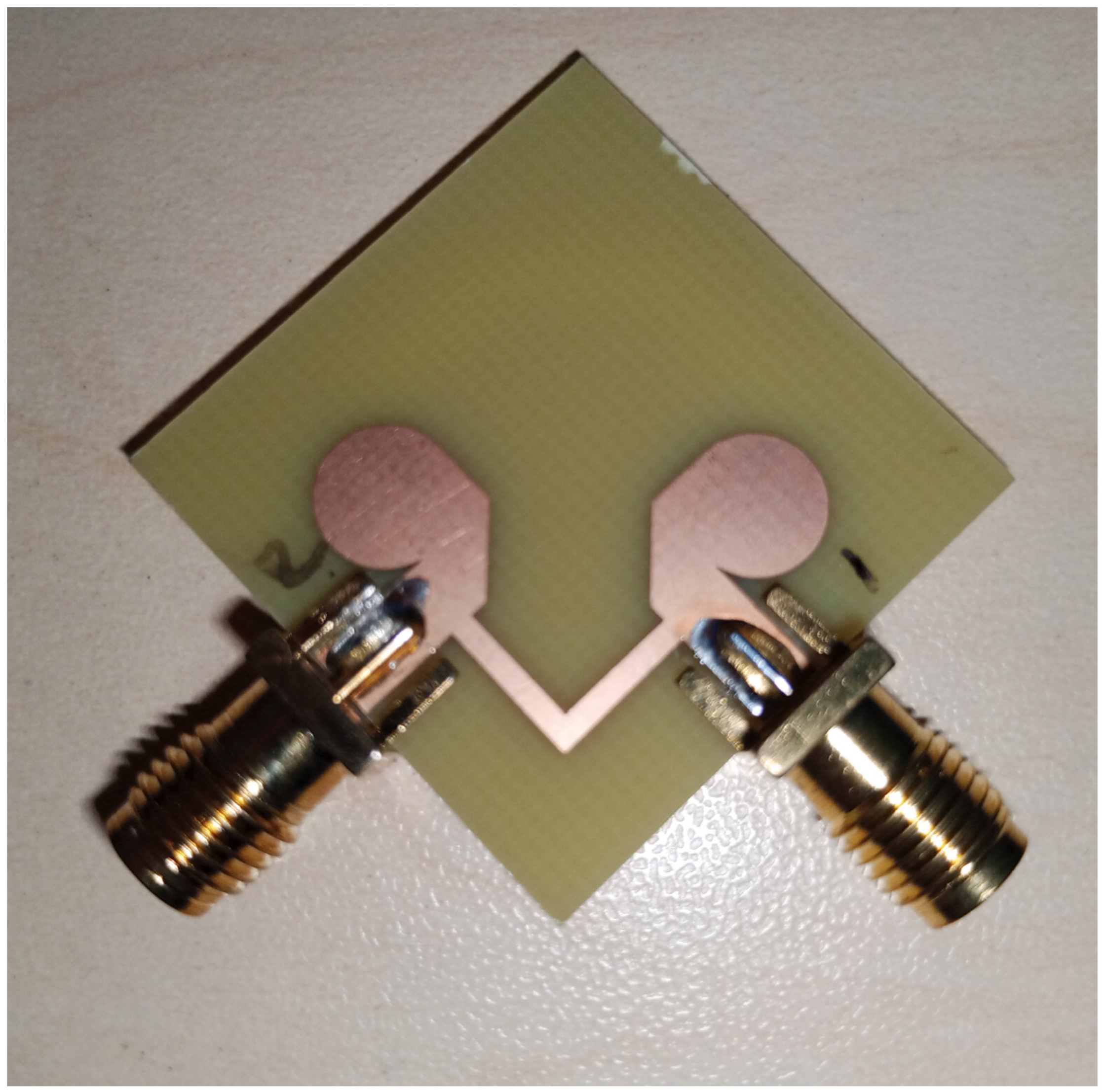
2. Single Unit Two Elements with Slotted Ground Design
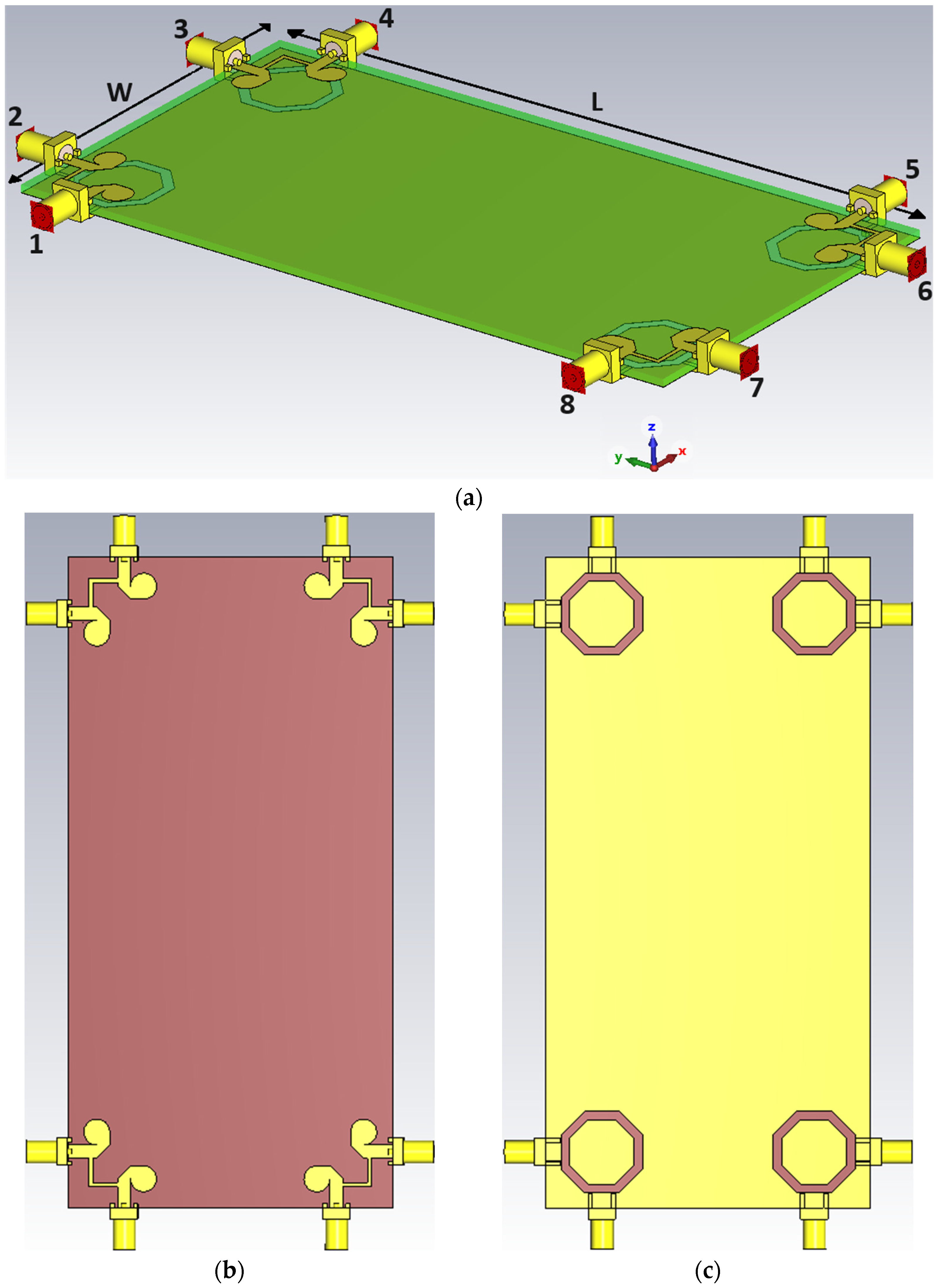
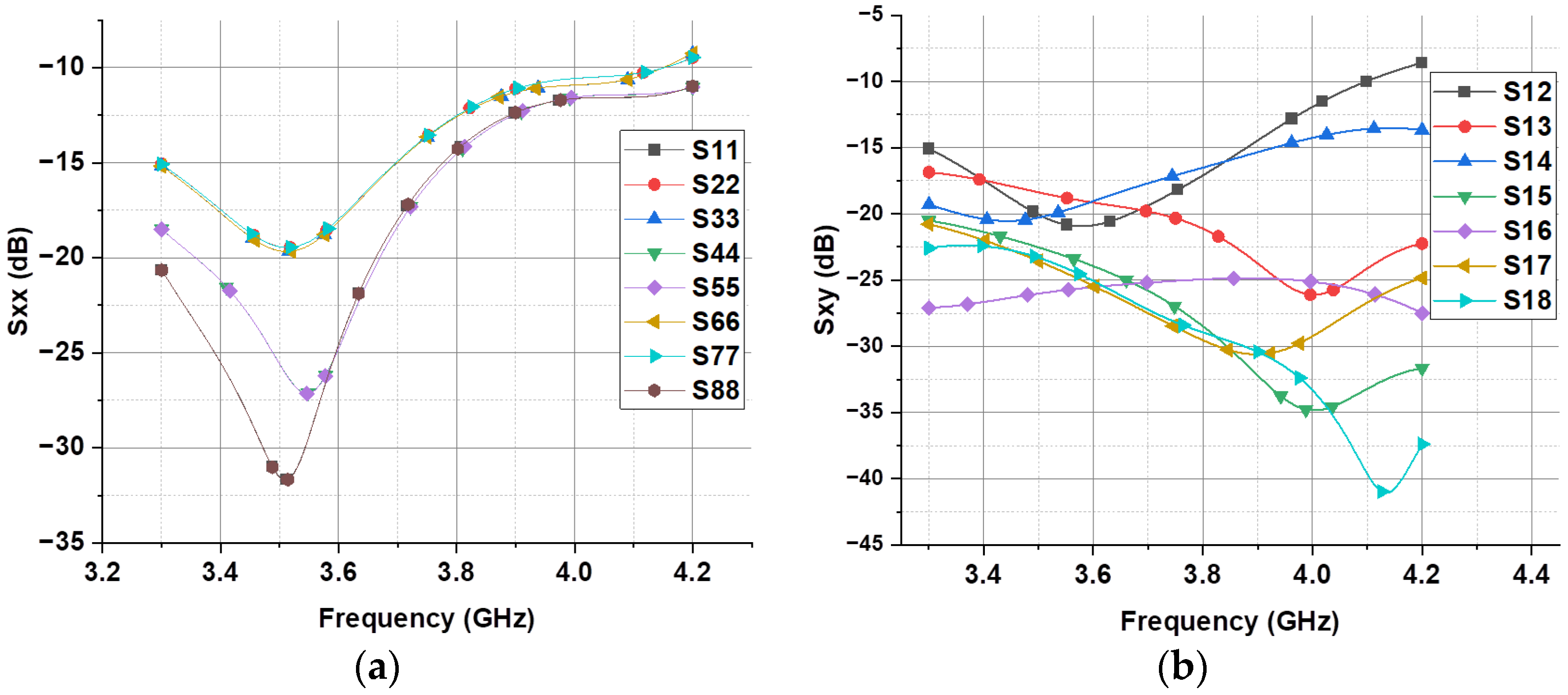
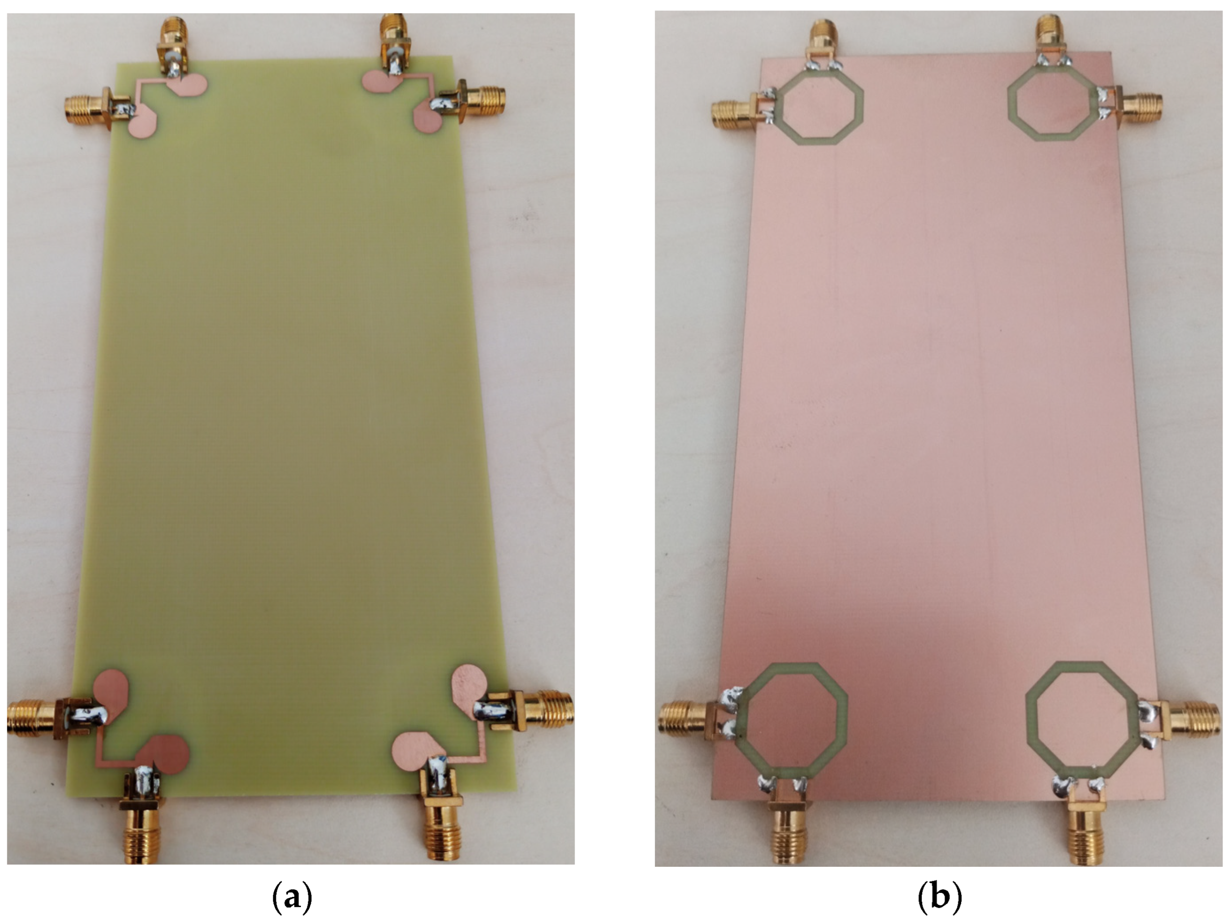
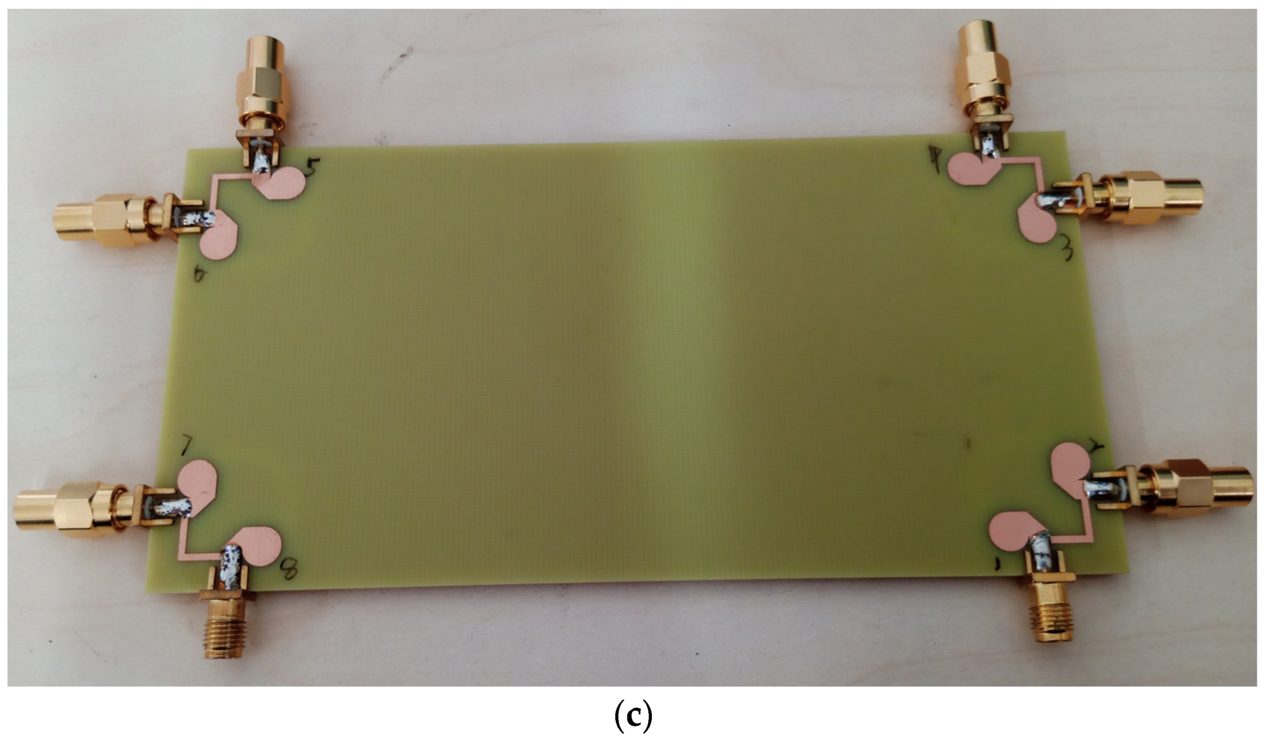
3. 8-Port MIMO for Handheld Devices Antenna Design
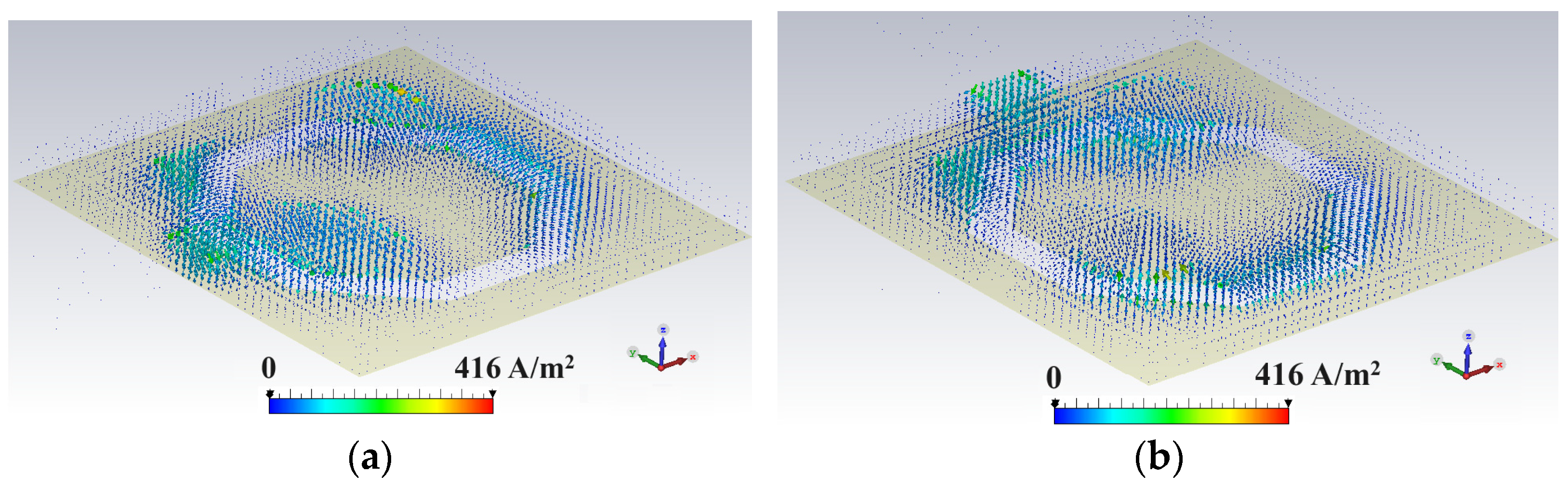
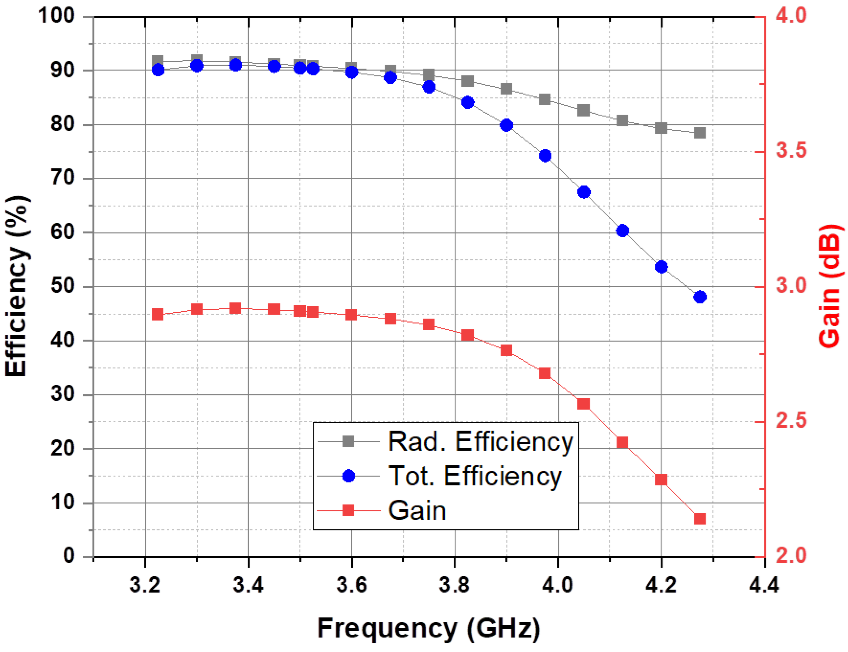
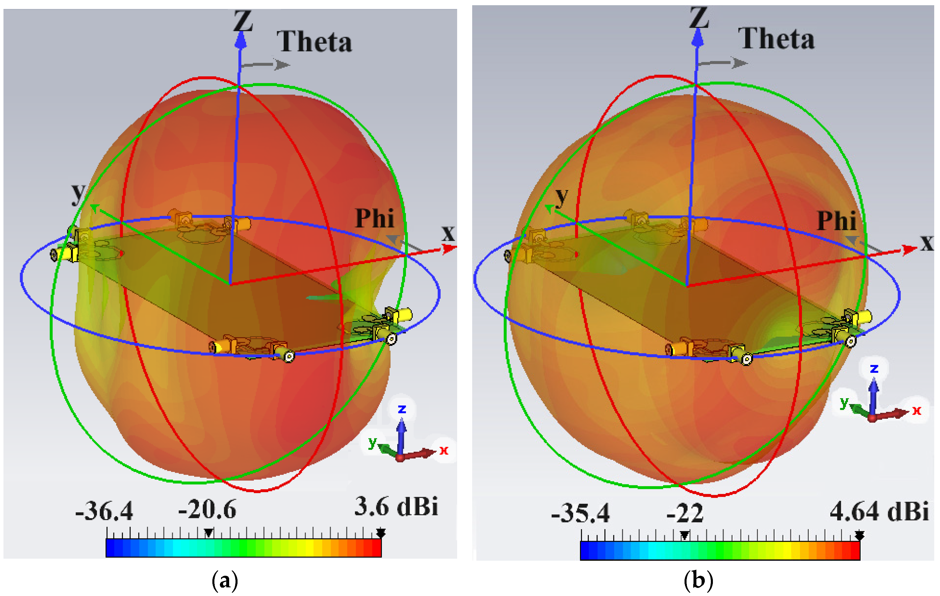
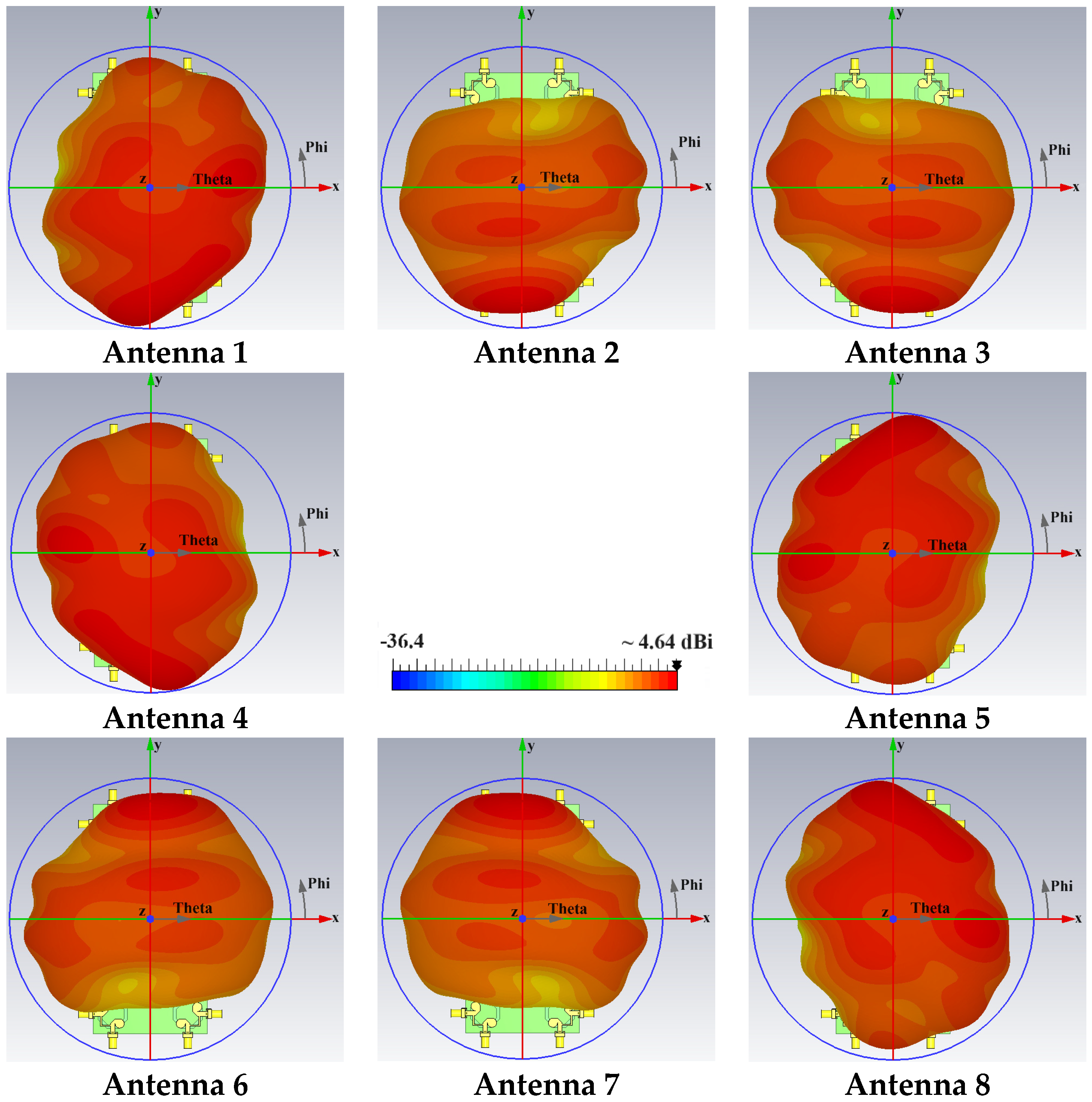
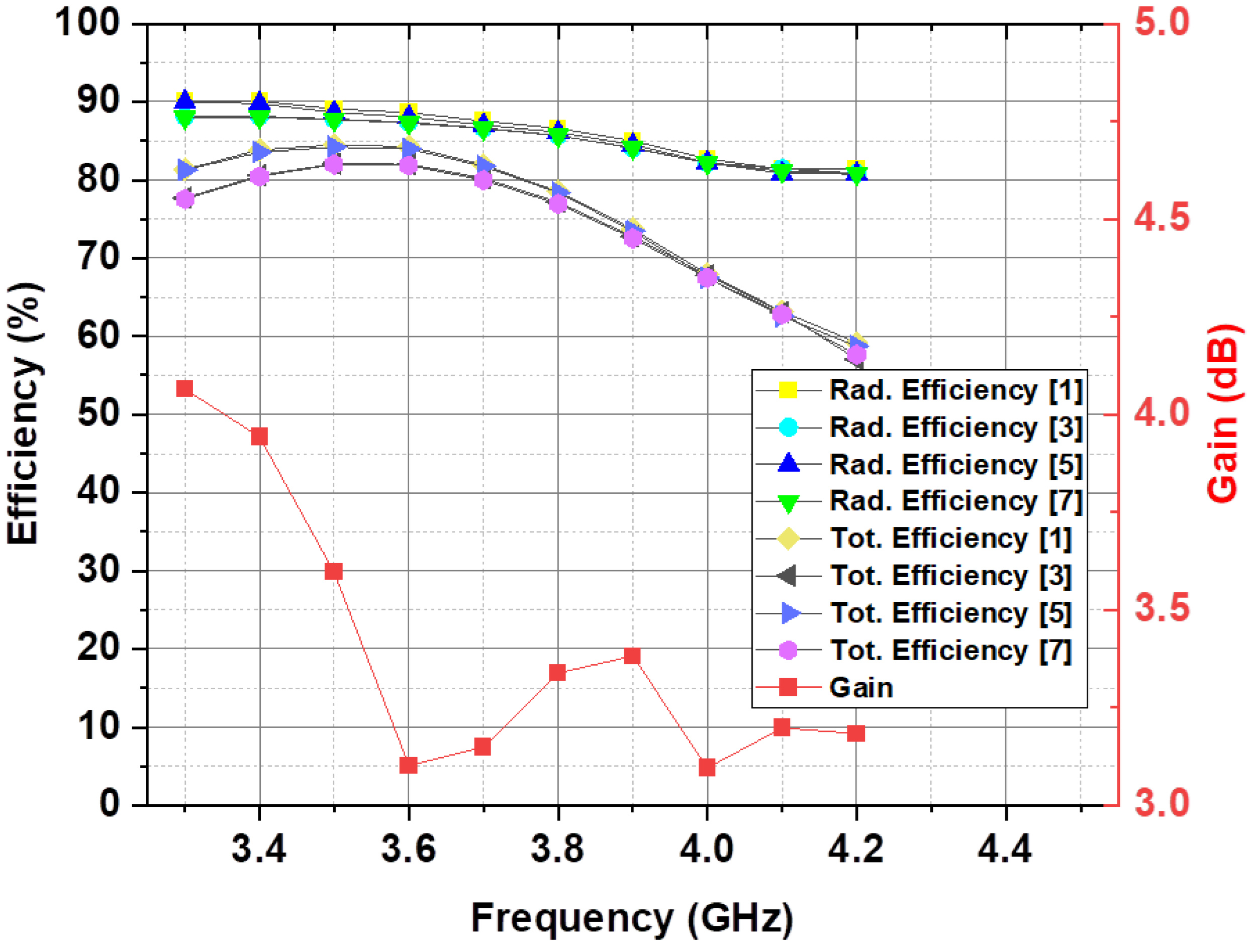
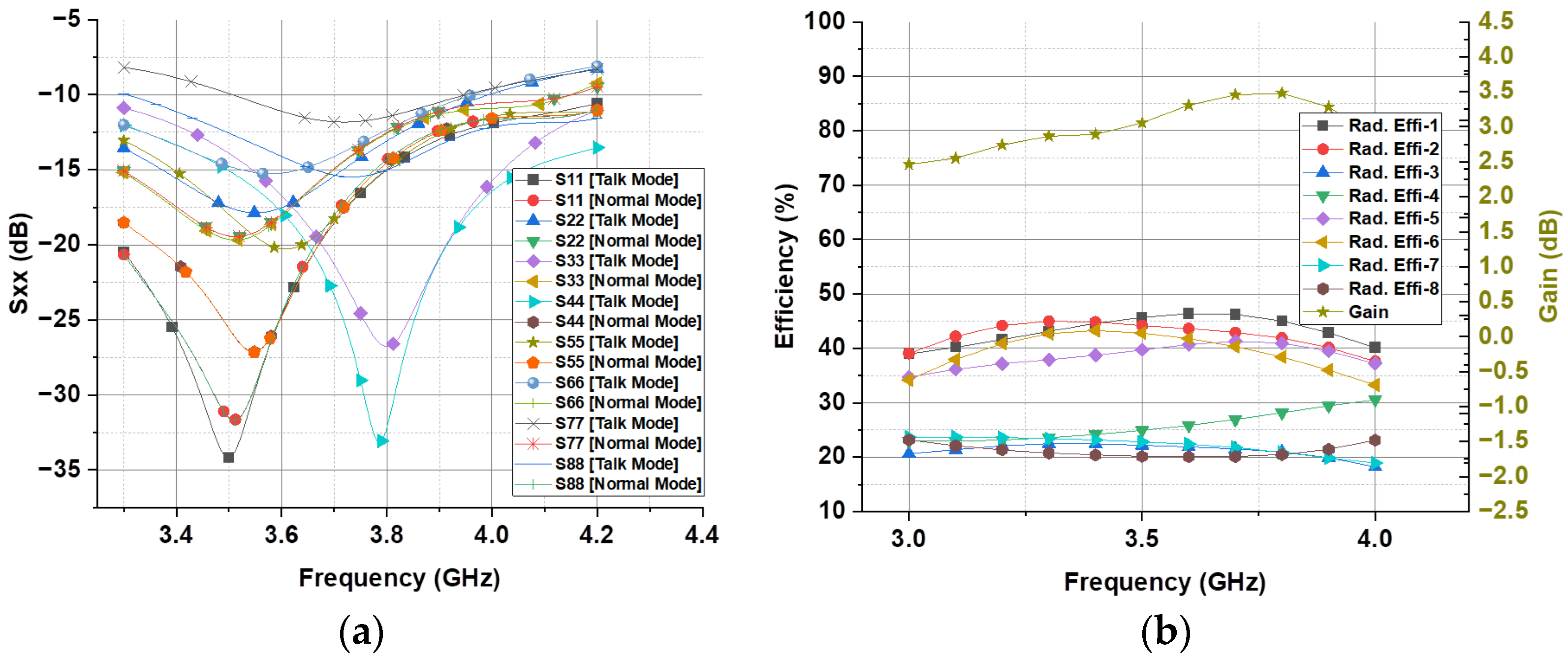
4. Effect on Antenna Array Performance during Operational Modes
5. Conclusions
Author Contributions
Funding
Data Availability Statement
Conflicts of Interest
Abbreviations
| MIMO | Multiple-input multiple-output |
| FR-4 | Flame retardant 4 |
| PCB | Printed circuit board |
| FR1 | Frequency range 1 |
| NR | New radio |
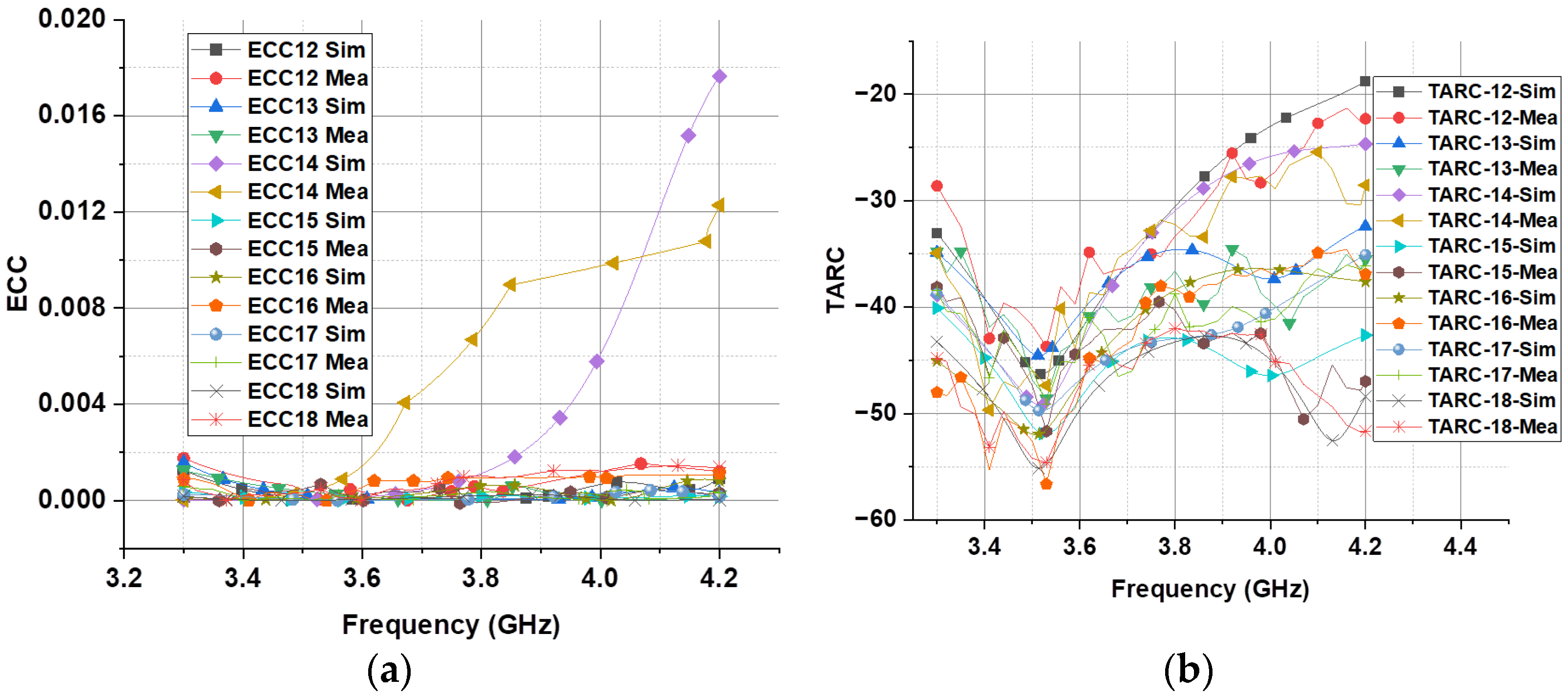
| ECC | Envelop correlation coefficient |
| TARC | Total active reflection coefficient |
| RF | Radio frequency |
| CST | Computer simulation technology |
| 3GPP | Third generation partnership project |
| IoT | Internet of Things |
| ORAN | Open radio access network |
References
- Chataut, R.; Akl, R. Massive MIMO systems for 5G and beyond networks—Overview, recent trends, challenges, and future research direction. Sensors 2020, 20, 2753. [Google Scholar] [CrossRef] [PubMed]
- Rajoria, S.; Trivedi, A.; Godfrey, W.W. A comprehensive survey: Small cell meets massive MIMO. Phys. Commun. 2018, 26, 40–49. [Google Scholar] [CrossRef]
- Parchin, N.O.; Basherlou, H.J.; Al-Yasir, Y.I.; Abd-Alhameed, R.A.; Abdulkhaleq, A.M.; Noras, J.M. Recent developments of reconfigurable antennas for current and future wireless communication systems. Electronics 2019, 8, 128. [Google Scholar] [CrossRef]
- Parchin, N.O.; Al-Yasir, Y.I.A.; Abd-Alhameed, R.A. A compact 5G antenna array with ultra-wide bandwidth for mm-wave smartphone applications. In Proceedings of the 15th European Conference on Antennas and Propagation (EuCAP), Dusseldorf, Germany, 22–26 March 2021. [Google Scholar]
- Hussain, R.; Sharawi, M.S. 5G MIMO antenna designs for base station and user equipment: Some recent developments and trends. IEEE Antennas Propag. Mag. 2021, 64, 95–107. [Google Scholar] [CrossRef]
- Brand, P.; Falk, J.; Sue, J.A.; Brendel, J.; Hasholzner, R.; Teich, J. Adaptive predictive power management for mobile LTE devices. IEEE Trans. Mob. Comput. 2020, 20, 2518–2535. [Google Scholar] [CrossRef]
- Ullah, A.; Parchin, N.O.; Abdul-Al, M.; Santos, H.M.; See, C.H.; Hu, Y.F.; Abd-Alhameed, R.A. Internal MIMO antenna design for multi-band mobile handset applications. In Proceedings of the 2021 29th Telecommunications Forum (TELFOR), Belgrade, Serbia, 23–24 November 2021; pp. 1–4. [Google Scholar]
- Parchin, N.O.; Basherlou, H.J.; Alibakhshikenari, M.; Parchin, Y.O.; Al-Yasir, Y.I.; Abd-Alhameed, R.A.; Limiti, E. Mobile-phone antenna array with diamond-ring slot elements for 5G massive MIMO systems. Electronics 2019, 8, 521. [Google Scholar] [CrossRef]
- Kiani, S.H.; Altaf, A.; Anjum, M.R.; Afridi, S.; Arain, Z.A.; Anwar, S.; Khan, S.; Alibakhshikenari, M.; Lalbakhsh, A.; Khan, M.A.; et al. MIMO antenna system for modern 5G handheld devices with healthcare and high rate delivery. Sensors 2021, 21, 7415. [Google Scholar] [CrossRef] [PubMed]
- Kiani, S.H.; Altaf, A.; Abdullah, M.; Muhammad, F.; Shoaib, N.; Anjum, M.R.; Damaševiˇcius, R.; Blažauskas, T. Eight element side edged framed MIMO antenna array for future 5G smart phones. Micromachines 2020, 11, 956. [Google Scholar] [CrossRef] [PubMed]
- Parchin, N.O.; Al-Yasir, Y.I.; Noras, J.M.; Abd-Alhameed, R.A. Dual-polarized MIMO antenna array design using miniaturized self-complementary structures for 5G smartphone applications. In Proceedings of the European Conference (EuCAP), Krakow, Poland, 31 March–5 April 2019; pp. 1–4. [Google Scholar]
- Li, Y.; Sim, C.-Y.-D.; Luo, Y.; Yang, G. High-isolation 3.5 GHz eight-antenna MIMO array using balanced open-slot antenna element for 5G smartphones. IEEE Trans. Antennas Propag. 2019, 67, 3820–3830. [Google Scholar] [CrossRef]
- Abdullah, M.; Altaf, A.; Anjum, M.R.; Arain, Z.A.; Jamali, A.A.; Alibakhshikenari, M.; Falcone, F.; Limiti, E. Future smartphone: MIMO antenna system for 5G mobile terminals. IEEE Access 2021, 9, 91593–91603. [Google Scholar] [CrossRef]
- Younas, T.; Zhao, Y.; Jeon, G.; Farid, G.; Tahir, S.; Mekonnen, M.; Shen, J.; Gao, M. A Framework to Connect IoT Edge Networks through 3D Massive MIMO. Wirel. Netw. 2023, 1–11. [Google Scholar]
- Younas, T.; Xing, X.; Shen, J.; Tahir, S.; Mekonen, M.; Gao, M. 3D Massive MIMO with Massive Connectivity for Internet of Things Devices. Wirel. Netw. 2023, 1–12. [Google Scholar]
- Long, D.; Wu, Q.; Fan, Q.; Fan, P.; Li, Z.; Fan, J. A power allocation scheme for MIMO-NOMA and D2D vehicular edge computing based on decentralized DRL. Sensors 2023, 7, 3449. [Google Scholar] [CrossRef] [PubMed]
- Pandey, A. Practical Microstrip and Printed Antenna Design; Artech House: Norwood, MA, USA, 2019. [Google Scholar]
- Parchin, N.O.; Al-Yasir, Y.I.A.; Basherlou, H.J.; Abd-Alhameed, R.A. A closely spaced dual-band MIMO patch antenna with reduced mutual coupling for 4G/5G applications. Prog. Electromagn. Res. C 2020, 101, 71–80. [Google Scholar] [CrossRef]
- Diman, A.A.; Karami, F.; Rezaei, P.; Amn-e-Elahi, A.; Mousavirazi, Z.; Denidni, T.A.; Kishk, A.A. Efficient SIW-feed network suppressing mutual coupling of slot antenna array. IEEE Trans. Antennas Propag. 2021, 69, 6058–6063. [Google Scholar] [CrossRef]
- Goud, J.R.; Rao, N.V.K.; Prasad, A.M. Design of triple band U-slot MIMO antenna for simultaneous uplink and downlink communications. Prog. Electromagn. Res. C 2020, 106, 271–283. [Google Scholar] [CrossRef]
- Wang, C.; Wang, H.; Wu, P.; Hou, M. Dual-band closed-slot MIMO antenna for terminal wireless applications. IEEE Trans. Antennas Propag. 2022, 70, 6514–6525. [Google Scholar] [CrossRef]
- Hussain, R.; Khan, M.U.; Sharawi, M.S. Dual-band Slot-Based MIMO Antenna Design with Independent Tuning. In Proceedings of the IEEE International Symposium on Antennas and Propagation and North American Radio Science Meeting, Montréal, QC, Canada, 5–10 July 2020. [Google Scholar]
- Chang, K.; Hsieh, L.-H. Microwave Ring Circuits and Related Structures; John Wiley Sons: Hoboken, NJ, USA, 2004; Volume 156. [Google Scholar]
- Batchelor, J.C.; Langley, R.J. Microstrip annular ring slot antennas for mobile applications. Electron. Lett. 1996, 32, 1635–1636. [Google Scholar] [CrossRef]
- Alibakhshikenari, M.; Babaeian, F.; Virdee, B.S.; Aissa, S.; Azpilicueta, L.; See, C.H.; Althuwayb, A.A.; Huynen, I.; Abd-Alhameed, R.A.; Falcone, F.; et al. A Comprehensive Survey on Various Decoupling Mechanisms with Focus on Metamaterial and Metasurface Principles Applicable for SAR and MIMO Systems. IEEE Access 2020, 8, 192965–193004. [Google Scholar] [CrossRef]
- Serghiou, D.; Khalily, M.; Singh, V.; Araghi, A.; Tafazolli, R. Sub-6 GHz dual-band 8× 8 MIMO antenna for 5G smartphones. IEEE Antennas Wirel. Propag. Lett. 2020, 19, 1546–1550. [Google Scholar] [CrossRef]
- Liu, R.; An, X.; Zheng, H.; Wang, M.; Gao, Z.; Li, E. Neutralization line decoupling tri-band multiple-input multiple-output antenna design. IEEE Access 2020, 8, 27018–27026. [Google Scholar] [CrossRef]
- Saleh, A.M.; Nagim, T.A.; Abd-Alhameed, R.A.; Noras, J.M.; See, C.H. Mutual coupling reduction of dual-band uni-planar MIMO system using neutralization line technique. Appl. Comput. Electromagn. Soc. J. (ACES) 2020, 35, 176–186. [Google Scholar]
- Birwal, A.; Singh, S.; Kanaujia, B.K.; Kumar, S. MIMO/diversity antenna with neutralization line for WLAN applications. MAPAN 2021, 36, 763–772. [Google Scholar] [CrossRef]
- Radio, N. User Equipment (UE) Radio Transmission and Reception—Part 1: Range 1 Standalone (Release 16). 3GPP TS 38101-1-G30, Technical Specification 2020. Available online: https://www.etsi.org/deliver/etsi_ts/138100_138199/13810101/16.04.00_60/ts_13810101v160400p.pdf (accessed on 8 May 2024).
- User Equipment. User Equipment (UE) Radio Transmission and Reception; Part 2: Range 2 Standalone. Part 1: Range 1 Standalone 2020. Available online: https://www.etsi.org/deliver/etsi_ts/138100_138199/13810102/16.04.00_60/ts_13810102v160400p.pdf (accessed on 8 May 2024).
- Li, Y.; Yuan, M.; Jia, Y.; Zhai, H.; Liu, C. A compact four port MIMO antenna using connected neutral lines for enhanced isolation. In Proceedings of the 2021 International Conference on Microwave and Millimeter Wave Technology (ICMMT), Nanjing, China, 23–26 May 2021; pp. 1–3. [Google Scholar]
- Elfergani, I.; Hussaini, A.S.; Rodriguez, J.; Abd-Alhameed, R. Antenna Fundamentals for Legacy Mobile Applications and Beyond; Springer: Berlin/Heidelberg, Germany, 2018; Volume 329. [Google Scholar]
- Hu, W.; Liu, X.; Gao, S.; Wen, L.-H.; Qian, L.; Feng, T.; Xu, R.; Fei, P.; Liu, Y. Dual-band ten-element MIMO array based on dual-mode IFAs for 5G terminal applications. IEEE Access 2019, 7, 178476–178485. [Google Scholar] [CrossRef]
- Al-Ani, N.M.K.; Al-Ani, O.A.S.; Mosleh, M.F.; Abd-Alhameed, R.A. A Dual-Polarized MIMO Array Antenna System for Future Smartphone. J. Phys. Conf. Ser. 2021, 1804, 012123. [Google Scholar] [CrossRef]
- Chizhik, D.; Ling, J.; Samardzija, D.; Valenzuela, R.A. Spatial and polarization characterization of MIMO channels in rural environment. In Proceedings of the 2005 IEEE 61st Vehicular Technology Conference, Stockholm, Sweden, 30 May–1 June 2005; Volume 1, pp. 161–164. [Google Scholar]
- Tiwari, R.N.; Singh, P.; Kanaujia, B.K.; Kumar, P. Compact circularly polarized MIMO printed antenna with novel ground structure for wideband applications. Int. J. RF Microw. Comput. Aided Eng. 2021, 31, e22737. [Google Scholar] [CrossRef]
- Gao, C.; Li, X.-Q.; Lu, W.-J.; Wong, K.-L. Conceptual design and implementation of a four- element MIMO antenna system packaged within a metallic handset. Microw. Opt. Technol. Lett. 2018, 60, 436–444. [Google Scholar] [CrossRef]


| Parameter | Value (mm) | Parameter | Value (mm) | Parameter | Value (mm) |
|---|---|---|---|---|---|
| W | 75 | Lg | 26 | Wn | 1 |
| L | 150 | Rp | 3 | Ln | 6.65 |
| h | 1.6 | Wf | 3 | Ws | 2.17 |
| Wg | 26 | Lf | 9.71 | Ls | 7.84 |
| Ref. # | Bandwidth | Element | Efficiency | Size | Peak Gain | Isolation | ECC |
|---|---|---|---|---|---|---|---|
| [9] | 3.4–3.6 (−6 dB) | 8 | 42–65 | 150 × 70 | 2.87 | 12 | <0.2 |
| [10] | 3.4–3.6 | 8 | 62–76 | 150 × 75 | N/A | 12 | <0.05 |
| [11] | 3.55–3.65 | 4 | 52–76 | 150 × 75 | N/A | 11 | N/A |
| [12] | 3.4–3.6 | 8 | 60–75 | 150 × 80 | N/A | 17 | <0.05 |
| [13] | 3.3–3.7 (−6 dB) | 8 | 50–70 | 136 × 68 | 4 | 15 | 0.1 |
| [38] | 3.45–3.55 (−6 dB) | 4 | 40–50 | 120 × 73 | 1.9 | 15 | <0.31 |
| Proposed | 3.3–4.2 | 8 | 80–88 | 150 × 75 | 4 | 21 | <0.017 |
Disclaimer/Publisher’s Note: The statements, opinions and data contained in all publications are solely those of the individual author(s) and contributor(s) and not of MDPI and/or the editor(s). MDPI and/or the editor(s) disclaim responsibility for any injury to people or property resulting from any ideas, methods, instructions or products referred to in the content. |
© 2024 by the authors. Licensee MDPI, Basel, Switzerland. This article is an open access article distributed under the terms and conditions of the Creative Commons Attribution (CC BY) license (https://creativecommons.org/licenses/by/4.0/).
Share and Cite
Khan, A.A.; Wang, Z.; Li, D.; Ahmed, A. A Compact C-Band Multiple-Input Multiple-Output Circular Microstrip Patch Antenna Array with Octagonal Slotted Ground Plane and Neutralization Line for Improved Port Isolation in 5G Handheld Devices. Electronics 2024, 13, 2196. https://doi.org/10.3390/electronics13112196
Khan AA, Wang Z, Li D, Ahmed A. A Compact C-Band Multiple-Input Multiple-Output Circular Microstrip Patch Antenna Array with Octagonal Slotted Ground Plane and Neutralization Line for Improved Port Isolation in 5G Handheld Devices. Electronics. 2024; 13(11):2196. https://doi.org/10.3390/electronics13112196
Chicago/Turabian StyleKhan, Asad Ali, Zhenyong Wang, Dezhi Li, and Ali Ahmed. 2024. "A Compact C-Band Multiple-Input Multiple-Output Circular Microstrip Patch Antenna Array with Octagonal Slotted Ground Plane and Neutralization Line for Improved Port Isolation in 5G Handheld Devices" Electronics 13, no. 11: 2196. https://doi.org/10.3390/electronics13112196