Article

Electron-Induced Single-Event Effect in 28 nm SRAM-Based FPGA

1
College of Electrical, Energy and Power Engineering, Yangzhou University, Yangzhou 225127, China
2
Innovation Academy for Microsatellites of Chinese Academy of Sciences, Shanghai 201203, China
3
China Academy of Space Technology, Beijing 100029, China
4
Institute of Special Environments Physical Sciences, Harbin Institute of Technology, Shenzhen 518055, China
5
Innovation Center for Radiation Application, Beijing 102413, China
*
Authors to whom correspondence should be addressed.
Electronics 2024, 13(12), 2233; https://doi.org/10.3390/electronics13122233
Submission received: 11 May 2024 / Revised: 1 June 2024 / Accepted: 5 June 2024 / Published: 7 June 2024

Abstract

:
As the feature size of integrated circuit decreases, the critical charge of single-event effect decreases as well, making nano-scale devices more susceptible to the high-energy charged particles during their application in space. Here, we study the electron-induced single-event effect in 28 nm static random-access memory (SRAM)-based field programmable gate array (FPGA) utilizing high-energy electrons with energy of 1 MeV~5 MeV. The experimental results demonstrate that the 3 MeV electrons can cause single-event functional interrupts (SEFIs) in FPGA, while the electrons with other energies cannot. To further explore the mechanism of electron-induced SEFIs in this nanoscale FPGA, we combined Monte Carlo, Technology Computer-Aided Design (TCAD), and Simulation Program with Integrated Circuit Emphasis (SPICE) simulations. It is revealed that the SEFI was mainly caused by the direct ionization effect of high-energy electrons, and the SEFI was related to the interactions between multiple sensitive nodes.

1. Introduction

In the space environment, there are various types of high-energy particles such as protons, electrons, and heavy ions. These charged particles will pass through the PN junction of the transistor, generating charges that are collected by the electrodes, causing logic cell upsets, functional interrupts, or burnout during device application in space. Diverse semiconductor materials can be made into different types and structures of transistors, which can be used in various fields such as biomedicine and aerospace fields [1]. Static random-access memory (SRAM)-based field programmable gate array (FPGA) offers comprehensive functions to address the requirements across a wide set of space applications. However, it is affected by charged particles when used in space, including single-event upset (SEU) in memory cells, single-event functional interrupt (SEFI) in control registers, and single-event latch-up (SEL) in parasitic structures of CMOS. Especially when the device feature size develops to nanoscale, as the operating voltage gradually decreases, the critical charge also decreases, making the circuit more sensitive to the single-event effect (SEE) [2,3,4,5,6,7].
In previous work, a considerable amount of research has focused on the SEE induced by protons and heavy ions in SRAM-based FPGA [8,9,10]. With deep space exploration, the spacecraft close to Jupiter may encounter significantly higher-energy electrons compared to those near Earth. In addition, cosmic rays can generate secondary particles, called δ-rays, which contain high-energy electrons; these environments could induce degradation or failure in the device [11]. Electron-induced SEU was observed in SRAMs and FPGAs with advanced technology [12,13,14]. King et al. [12] and Trippe et al. [13] reported that the SEU in a device was caused by the direct ionization effects of electrons with energy below 100 keV, while electron-induced upsets were ascribed to indirect ionization induced by electron with the energy above 9 MeV [14,15,16]. The mechanism of electron-induced SEU was closely related to the electron energy [12,13,14,15,16].
Up to now, most studies have focused on the electron-induced SEU in memory cells of FPGA, and it remains to be investigated whether energy electrons can induce SEU in logic units, thereby causing SEFIs in devices. Due to the peak energy of electrons trapped in the Van Allen radiation belt typically reaching around 5 MeV [15], it is crucial to study the SEE caused by electrons in this energy range. To assess the sensitivity of FPGA to SEE induced by different energy electrons, here, the SEE in 28 nm SRAM-based FPGA was investigated utilizing electrons with an energy range of 1~5 MeV. We found that 3 MeV electrons can cause SEFI in FPGA, while the electrons with other energies cannot. In combined Monte Carlo, TCAD, and SPICE simulations, the mechanism was attributed to direct ionization effect of electrons, and the SEFI depends on the interactions between multiple sensitive nodes.

2. Experimental Details

2.1. Device under Test

The Device Under Test (DUT) is a 28 nm Virtex-7 SRAM-based FPGA with 693120 logic cells manufactured by Xilinx Corporation, San Jose, CA, USA (XC7VX690T). It is packaged in a flip-chip configuration. The DUT operates with an I/O voltage of 1.8V and core voltage of 1V. Virtex-7 SRAM-based FPGAs offer flexible logic resources such as Configurable Logic Block (CLB), flip-flop (FF), Digital Signal Processor (DSP), Block RAM (BRAM), Power-on Reset (POR), and other extensive resources. The XC7VX690T of the Virtex-7 family includes the mentioned resources and supports the functional architectures conveniently. CLBs and BRAM are used as memory cells, while the POR circuit is used as a control logic circuit.

2.2. Experimental Setup

Electron irradiation experiments on devices were carried out in the electron linear accelerator at the National Space Science Center (NSSC) of the Chinese Academy of Sciences. During the electron irradiation, the energies were selected as 1 MeV, 2 MeV, 3 MeV, 4 MeV, and 5 MeV, respectively, and the fluence was 1 × 1012 cm−2. The DUT was installed on the sample holder in the electron irradiation chamber (Figure 1), and its status of function was checked normal before electron irradiation.
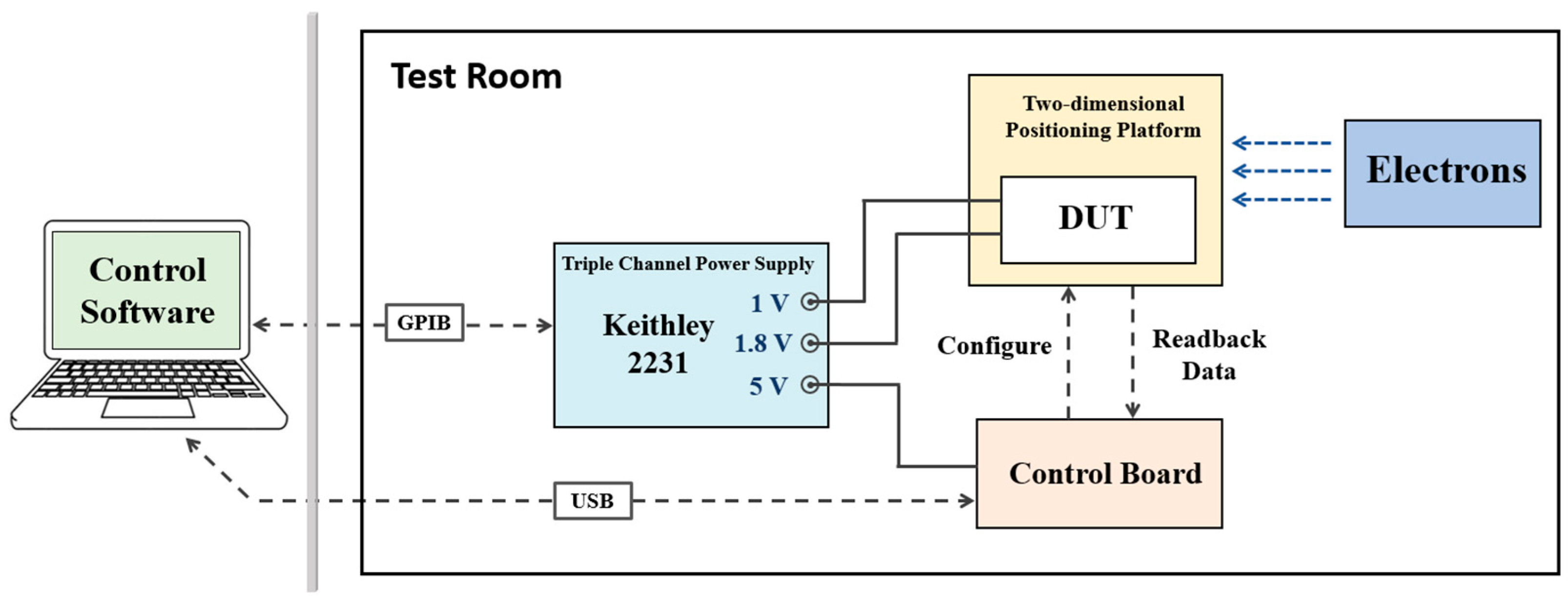
Based on the characteristics of SRAM-based FPGA devices, the SEE test system is shown in Figure 2. The test system included a triple-channel power supply, control board, DUT, and computer. The Keithley 2231 SourceMeter was selected as the three-channel power supply to supply power to the SEE test system, providing 5 V voltage for the control board and 1 V and 1.8 V voltage for the test board. This was controlled remotely by the laptop over a GPIB line. The control board was used to communicate with the computer, including sending and receiving test data. The DUT was connected to the control board to realize configuration and data reading functions. The SEE test system can detect both SEFI and SEU.
Before the electron irradiation, the status of DUT was checked to make sure there was no original error in the FPGA. There was no SEFI or SEU in all modules, and the core current was 622 mA. During the electron irradiation, the computer sent and read data periodically, and the core current was monitored simultaneously. If the core current increases to 1.5 times higher than normal and can only recover via power restart, it will be recorded as SEL.
According to SEE sensitivity in different FPGA modules, the SEFI test was performed in POR and Select-MAP (SMAP) register. In electronic irradiation experiments, monitoring is carried out of the status register DONE signal. If it is low, it indicates that the POR function has failed. Continuously read and write data to the FAR register. If the read and written data do not match, it indicates that SEFI has occurred at the SMAP register. The test results for SEFI are either PASS or FAIL.
CLB and BRAM are sensitive regions for SEU. The content of SEU covers two types of resources. In SEU testing, the data storage functions of the CLB and BRAM modules were tested. CLB is configured as a shift register. The initial value was moved into the shift register. After the irradiation, the data were removed, and the number of errors was compared. The SEU test of BRAM was carried out by comparing the read-back bitstream data with the preset standard data. The SEU test results indicate the number of flips in CLB and BRAM.

3. Experimental Results

The experimental results under electron irradiation with different energies are shown in Table 1. When the electron energy was 3 MeV, SEFI occurred in the POR register, and a large number of SEUs were observed in CLB and BRAM. Under other electron energies, there was no SEL, SEFI, or SEU observed in the DUT. These experimental results show that the nano-scale FPGA has significant sensitivity in SEE under electron irradiation of some specific energy.

4. Simulation and Discussion

Experimental results show that SEFI occurred in the POR register, and SEU was observed in the CLB and BRAM only when FPGA is irradiated by 3 MeV electrons. In order to further explore the mechanism of electron-induced SEE, the Monte Carlo simulation tool Geant4 was used to investigate the physical interaction between the electrons and the POR register of the FPGA. Based on the simulation results from Geant4, a combination of TCAD and SPICE simulations were further used to establish device-level and circuit-level models to analyze the variation in device characteristics and its underlying mechanism during electron irradiation.

4.1. Monte Carlo Simulations

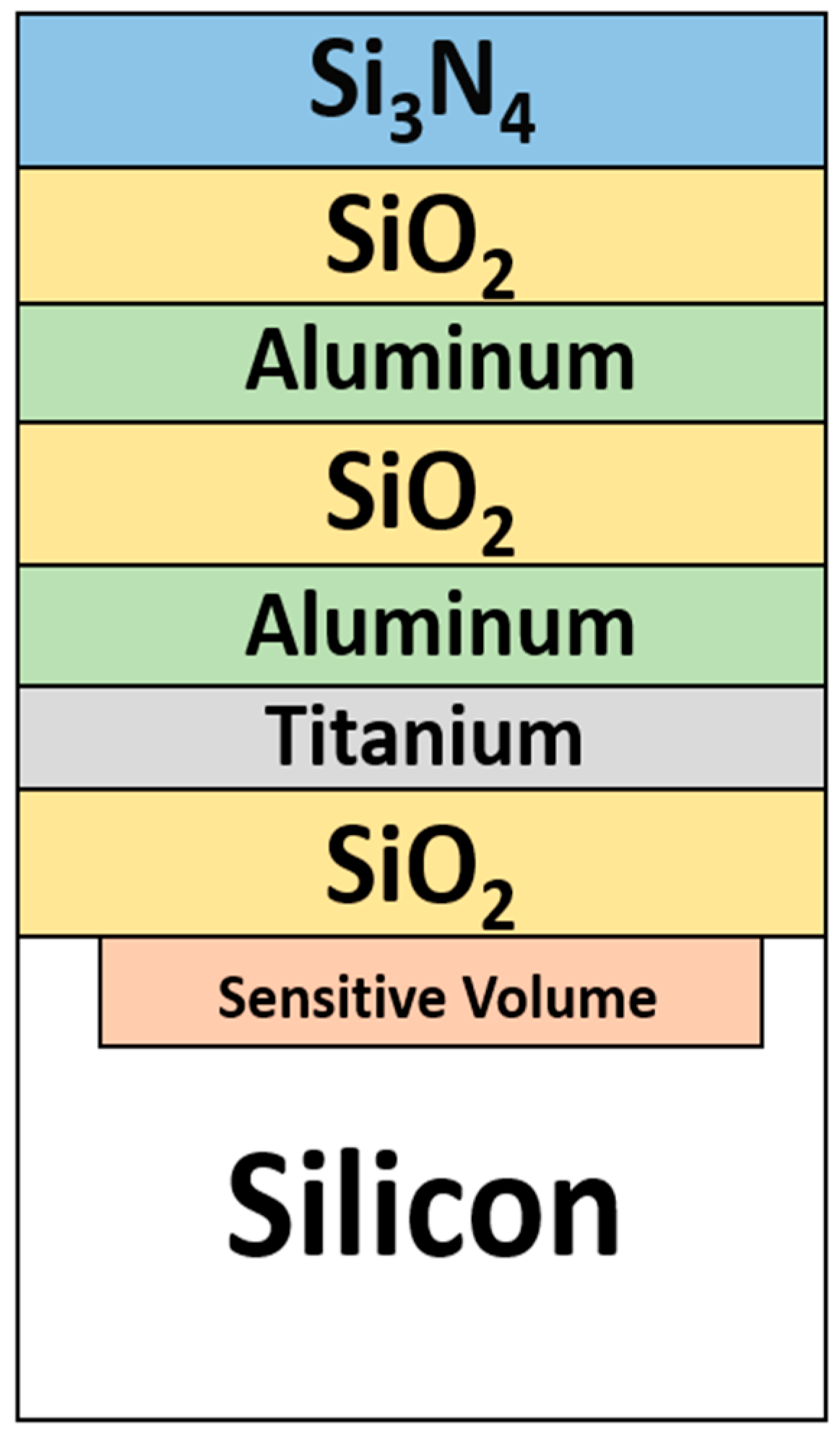
Through the Geant4 [17,18], ionization energy loss (IEL) and non-ionization energy loss (NIEL) in the fundamental MOSFET structure of the POR register under electron irradiation with different energies were obtained [19]. The geometric structure in Geant4 simulation is shown in Figure 3.
The sensitive volume was placed in silicon with the dimension of 1 μm × 1 μm × 0.5 μm, and the deposition energy within this sensitive volume was recorded. The electron fluence used in simulation was 1 × 1012 cm−2, and the energies were 1, 2, 3, 4, and 5 MeV, which was the same process as that in the experiment.
Energy deposition is the energy transferred or deposited by an incoming particle into a material when it interacts with that material. Geant4 was used to compute the energy deposition of the events in the sensitive volume (orange cube) after particles were transported through surrounding metal materials. The energy deposited in the sensitive region is recorded for each event that passes through it. Therefore, the linear energy transfer (LET) distribution at different electron energies was further obtained according to LET = dE/(ρdx).
Since the LET threshold for SEU in 28 nm BRAM was previously found to be 0.12 MeV·cm2/mg and was even higher for 28 nm flip-flop [8,20], we divided the LET distribution into five regions, namely: 0.1 MeV·cm2/mg~0.3 MeV·cm2/mg, 0.3 MeV·cm2/mg~0.5 MeV·cm2/mg, 0.5 MeV·cm2/mg~0.8 MeV·cm2/mg, 0.8 MeV·cm2/mg~1 MeV·cm2/mg, and higher than 1 MeV·cm2/mg.
The LET distribution produced by different electron energy is shown in Figure 4. When the electron energy is 3 MeV, the LET distribution has the highest probability in the range of higher than 0.3 MeV·cm2/mg, which is 71.4%.
The interaction mechanism between high-energy electrons and DUT mainly includes direct ionization and indirect ionization. According to the simulation results of Geant4, the secondary particles generated by the incident of high-energy electrons are still mainly electrons. There are no heavy ions observed in the secondary particles, so the indirect ionization effect can be almost ignored. The main way to cause energy deposition in the device is directly ionization, which is consistent with the previous findings that the electrons below 10 MeV deposit energy mainly via direct ionization [21,22].

4.2. TCAD and Spice Simulations

Furthermore, we employed a comprehensive approach combining TCAD and SPICE to simulate the influence of SEFI on the device characteristics and the LET threshold of SEFI.
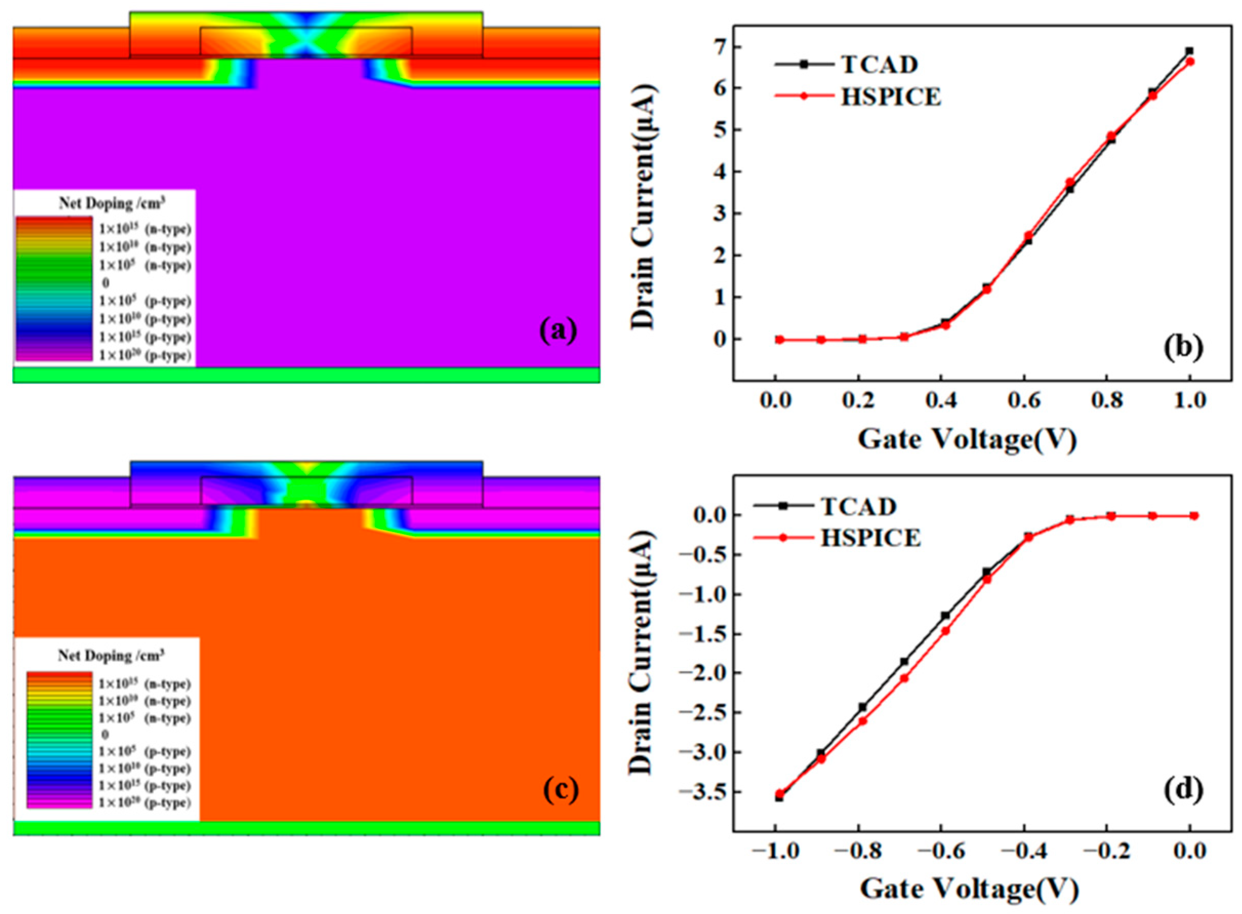
The fundamental unit of the POR register is a 28 nm bulk MOSFET which was modeled by TCAD with the parameters as shown in Table 2.
The characteristics curves of 28 nm bulk MOSFET were obtained by TCAD simulation, as shown in Figure 5. Using the maximum transconductance method [23], the MOS device threshold voltage was determined to be 0.29 V, which is close to the actual device [22]. A SPICE model can be further built after extracting the device parameters from TCAD results. As shown in Figure 5, the TCAD simulation results and the HSPICE simulation results agree well with each other, proving that the extracted SPICE model can be further used to build a circuit-level model for the POR register.
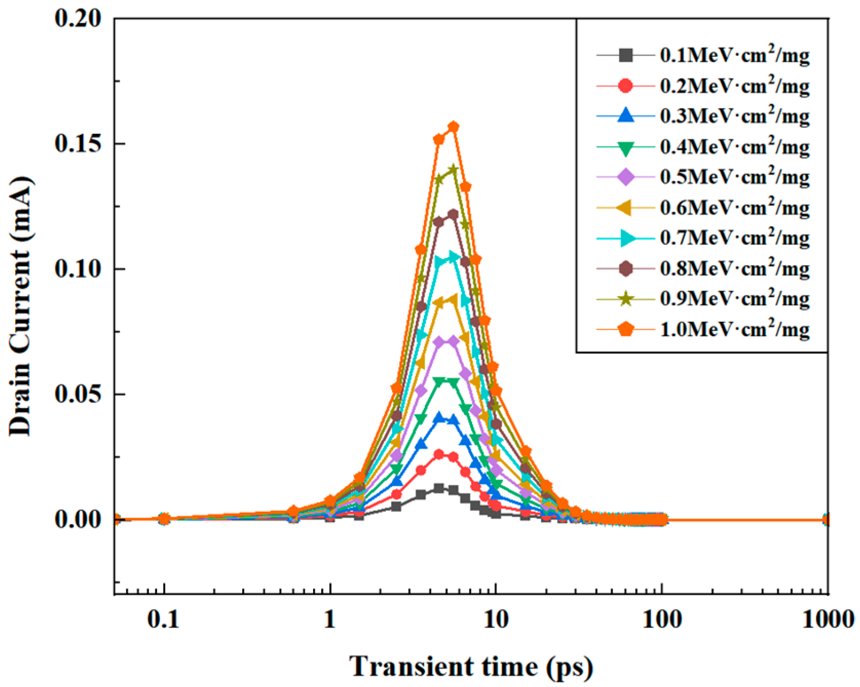
To investigate the influence of SEE on the device, we simulated the SEE-induced transient current in the TCAD model of the device. We defined the particle type, and the particles were vertically incident on the drain and passed through the device with a track radius of 0.02 μm. Since the distribution has the highest probability in the range of 0.1~1 MeV∙cm2/mg derived from Geant4 simulation above, the particle-induced single-event transient currents under this LET range were simulated via the TCAD model. As shown in Figure 6, the transient currents occur within a period of several tens of picoseconds, and the amplitude increases with the increase in the LET value.
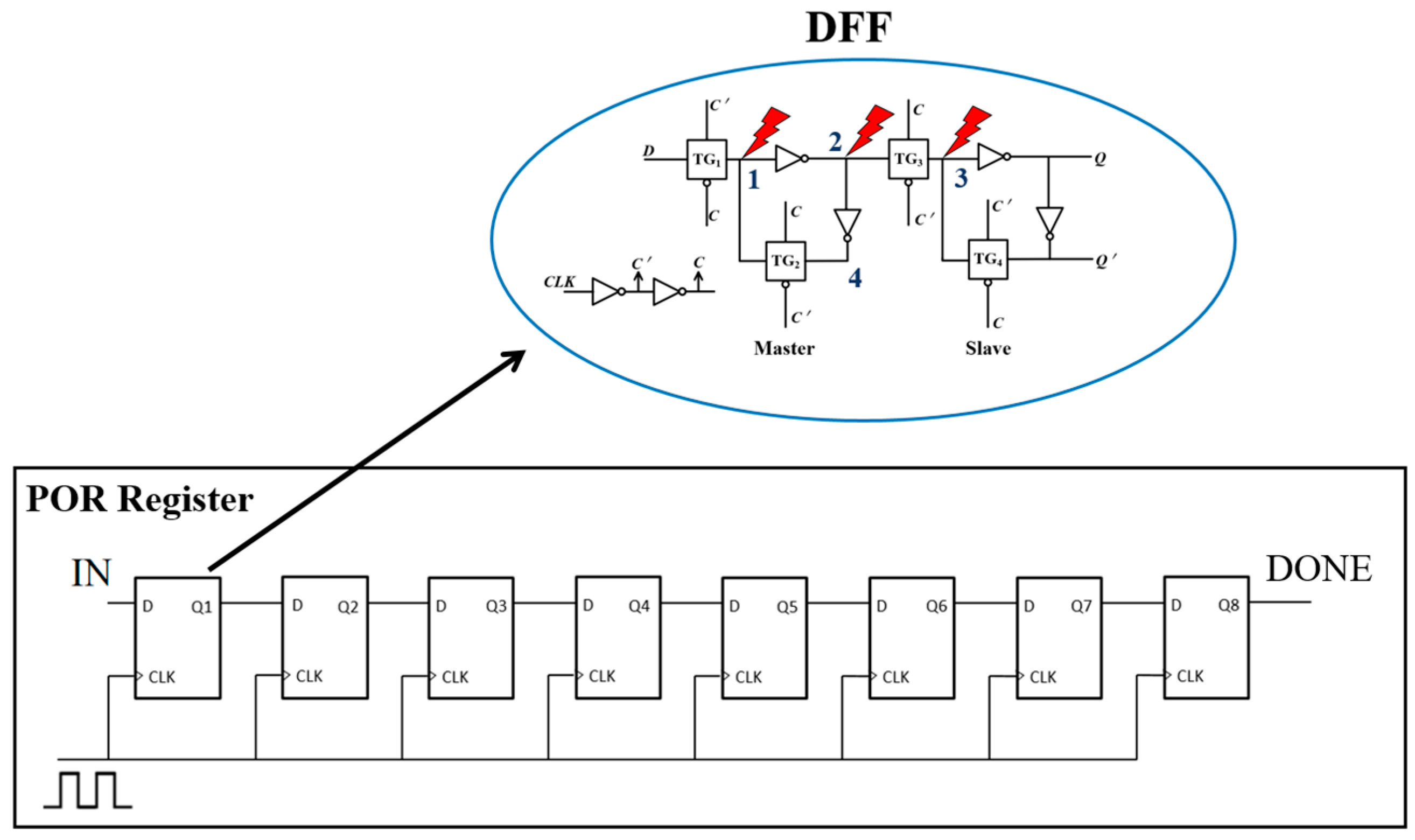
In order to further explore the influence of SEE, the equivalent circuit of the POR register was established utilizing the SPICE model. Whether SEFI has occurred in the POR register can be judged by the DONE port signal state in the POR register. If the DONE signal voltage is low, it is determined that SEFI has occurred. The sequential diagram of the DONE signal state can be obtained from the Xilinx overview [24], and the DONE signal state changes from “0” to “1” after eight clock periods to realize the configuration function. According to previous studies [25,26], the equivalent POR register structure including eight D flip-flops was built, which can implement the DONE sequential function (Figure 7). The configuration function of the POR register was simulated when there is no fault injected to the circuit, and sequential function of the POR register was simulated to check whether SEFI occurred when there is a fault injected into the circuit.
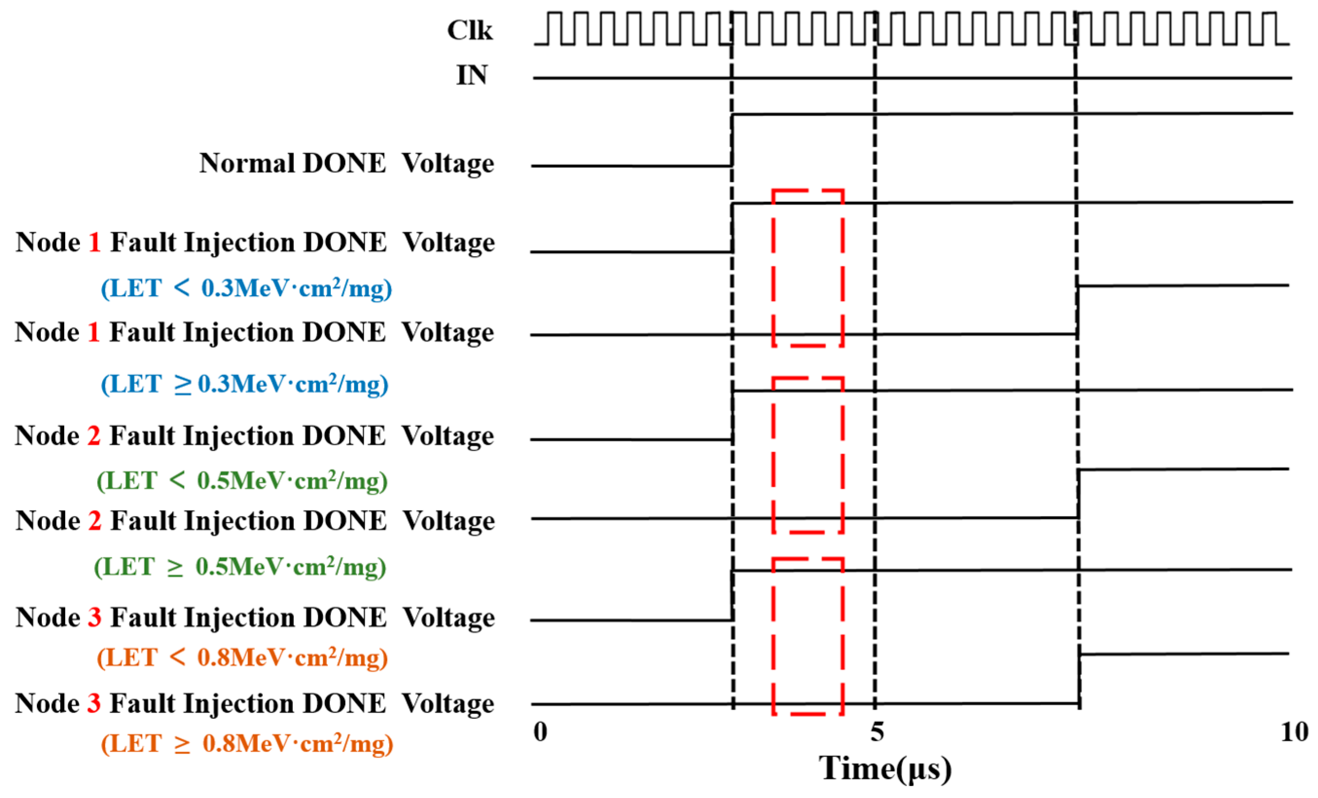
The SEE-induced transient currents for different LET values (Figure 6) were injected into circuit nodes 1, 2, and 3 of the POR register (Figure 7) as fault, respectively. The critical LET values of SEFI were determined according to the DONE port signal state in the POR register. The simulation results of fault injection into different nodes are shown in Figure 8. When no fault is injected into the circuit, the DONE state transitions from low to high after eight clock periods, achieving the normal configuration function (Normal DONE Voltage in Figure 8). However, when the faults with different LET values and a duration of 5 μs are injected into each node separately, the DONE state transition may not happen, indicating the existence of SEFI. The LET thresholds that cause SEFI for different fault injection nodes were simulated by increasing LET with a step of 0.1 MeV·cm2/mg. When LET value increases to the threshold, the DONE state cannot transition from “0” to “1” within 5 μs, marked as red boxes in Figure 8, and returns to normal function after the fault duration of 5 μs. It is found that when a single-event transient current is injected into nodes 1, 2, and 3, the LET thresholds for SEFI are 0.3 MeV·cm2/mg, 0.5 MeV·cm2/mg, and 0.8 MeV·cm2/mg, respectively, as shown in Figure 8. Since node 1 has the lowest LET threshold for SEFI, this node is the most sensitive location for single-event soft errors in the device.
The mechanism of different sensitivity in different nodes can be understood as follows. Any changes in input are reflected at node 4, which is reflected at the DONE at the next positive edge of the eight clock periods. If input changes, the changes would be reflected only at node 4 when the CLK signal is low, and it will appear at the output only when the CLK is high. When the fault is injected into node 1 and lasts for 5 μs, node 4 keeps retaining the previously stored value of “0”, and it will be reflected in the DONE signal at the next positive edge of the CLK signal. Therefore, the DONE signal state remains low, the normal configuration function cannot be realized, and SEFI occurs in the device. Node 1 is at the master stage of the D flip-flop, and node 2 and node 3 are at the slave stage, which is related to the master stage. Therefore, node 1 is more sensitive than the other nodes and has the lower LET threshold of SEFI.
The master–slave stage of the D flip-flop is connected by the source–drain terminals at the transmission gate, so there is current interaction between the master stage and slave stage, which plays a role of transfer. The flip of the master stage is transmitted to the slave stage, and the storage state of the slave stage also changes the storage state of the master stage. Therefore, there is mutual influence between different sensitive nodes.
Combined with SPICE simulation results, due to the sensitive volume being small and the large number of transistors affected, the electron-induced transient current not only affects multiple sensitive nodes but also causes interaction between different sensitive nodes. Finally, the SEFI occurs under the irradiation of high-energy electrons.
The above combined simulation results show that the LET threshold for SEFI in SRAM-based FPGA is 0.3 MeV·cm2/mg. According to Figure 4, compared with other energies, when the electron energy is 3 MeV, the probability of LET distribution in the range of greater than 0.3 is higher than other energies. This can be attributed to the mechanism as the reason why the device was more sensitive to the 3 MeV electrons. However, the reason that the peak effect in experiments, i.e., the SEFI can only be observed at 3 MeV while not for other energies is not clear. We consider that it may be due to the relatively low probability of SEFI for other energies and not high enough fluence in experiments. In addition, SEU in CLB and BRAM is due to the function failure of the test system caused by SEFI.

5. Conclusions

Electron-induced SEE was investigated in a 28 nm bulk SRAM-based FPGA utilizing high-energy electrons with energy of 1 MeV~5 MeV, and the SEFI was observed when the electron energy was 3 MeV. Monte Carlo simulation shows that the method of electron deposition energy is mainly direct ionization. A SEE model of the POR register was built via the combination of TCAD and SPICE, revealing that the node near the device input is the most sensitive location for SEE, and the LET threshold is 0.3 MeV·cm2/mg. Since the LET distribution has the highest probability in the range of higher than 0.3 MeV·cm2/mg when electron energy is 3 MeV, and due to the sensitive volume being small and the large number of transistors affected, the electron-induced transient current affects multiple sensitive nodes leading to SEFI in the device. Consequently, the probability of SEFI occurrence is greater at 3 MeV compared to other energies. Therefore, when using this or similar FPGAs in space applications, it is crucial to pay special attention to the flux of 3 MeV electrons and implement shielding to protect against electrons around this energy level. These findings provide experimental and simulation support for the operation of nanoscale bulk SRAM-based FPGA in high-energy electron irradiation environments.

Author Contributions

J.T.: Methodology, Software, Investigation, Writing—review and editing. R.C.: Conceptualization, Methodology, Writing—review and editing, Supervision. Y.L.: Software, Investigation. Y.C.: Software, Investigation. B.M.: Investigation, Formal analysis. L.Z.: Investigation, Formal analysis. S.C.: Software, Investigation. H.L.: Investigation, Formal analysis. Y.X.: Conceptualization, Supervision. All authors have read and agreed to the published version of the manuscript.

Funding

This research was funded by Postgraduate Research and Practice Innovation Program of Jiangsu Province grant number No. SJCX23_1928.

Data Availability Statement

Data are contained within the article.

Conflicts of Interest

The authors declare that they have no known competing financial interests.

References

  1. Biswas, S.; Jang, H.; Lee, Y.; Choi, H.; Kim, Y.; Kim, H.; Zhu, Y. Recent advancements in implantable neural links based on organic synaptic transistors. Exploration 2014, 4, 20220150. [Google Scholar] [CrossRef]
  2. Dodd, P.E.; Sexton, F.W. Critical Charge Concepts for CMOS SRAMs. IEEE Trans. Nucl. Sci. 1995, 42, 1764–1771. [Google Scholar] [CrossRef]
  3. Barak, J.; Murat, M.; Akkerman, A. SEU due to electrons in silicon devices with nanometric sensitive volumes and small critical charge. Nucl. Instrum. Methods Phys. Res. B 2012, 287, 113–119. [Google Scholar] [CrossRef]
  4. Koga, R.; Penzin, S.H.; Crawford, K.B.; Crain, W.R. Single Event Functional Interrupt (SEFI) Sensitivity in Microcircuits. In Proceedings of the 1997 European Conference on Radiation and Its Effects on Components and Systems (RADECS), Cannes, France, 15–19 September 1997; pp. 311–318. [Google Scholar]
  5. Hiemstra, D.M.; Kirischian, V. Single Event Upset Characterization of the Virtex-6 Field Programmable Gate Array Using Proton Irradiation. In Proceedings of the 2012 IEEE Radiation Effects Data Workshop (REDW), Miami, FL, USA, 16–20 July 2012; pp. 1–4. [Google Scholar]
  6. Tonfat, J.; Lima Kastensmidt, F.; Artola, L.; Hubert, G.; Medina, N.H.; Added, N.; Aguiar, V.A.P.; Aguirre, F.; Macchione, E.L.A.; Silveira, M.A.G. Analyzing the Influence of the Angles of Incidence and Rotation on MBU Events Induced by Low LET Heavy Ions in a 28-nm SRAM-Based FPGA. IEEE Trans. Nucl. Sci. 2017, 64, 2161–2168. [Google Scholar] [CrossRef]
  7. Maillard, P.; Hart, M.; Barton, J.; Jain, P.; Karp, J. Neutron, 64 MeV Proton, Thermal Neutron and Alpha Single-Event Upset Characterization of Xilinx 20 nm UltraScale Kintex FPGA. In Proceedings of the 2015 IEEE Radiation Effects Data Workshop (REDW), Boston, MA, USA, 13–17 July 2015; pp. 1–5. [Google Scholar]
  8. Lee, D.S.; Wirthlin, M.; Swift, G.; Le, A.C. Single-Event Characterization of the 28 nm Xilinx Kintex-7 Field-Programmable Gate Array under Heavy Ion Irradiation. In Proceedings of the 2014 IEEE Radiation Effects Data Workshop (REDW), Paris, France, 14–18 July 2014; pp. 1–5. [Google Scholar]
  9. Wang, Z.; Chen, W.; Yao, Z.; Zhang, F.; Luo, Y.; Tang, X.; Guo, X.; Ding, L.; Peng, C. Proton-Induced Single-Event Effects on 28 nm Kintex-7 FPGA. Microelectron. Reliab. 2020, 107, 113594. [Google Scholar] [CrossRef]
  10. Quinn, H.; Graham, P.; Krone, J.; Caffrey, M.; Rezgui, S. Radiation-Induced Multi-Bit Upsets in SRAM-Based FPGAs. IEEE Trans. Nucl. Sci. 2005, 52, 2455–2461. [Google Scholar] [CrossRef]
  11. Garrett, H.B.; Katz, I.; Jun, I.; Kim, W.; Whittlesey, A.C.; Evans, R.W. The Jovian Charging Environment and Its Effects—A Review. IEEE Trans. Plasma Sci. 2012, 40, 144–154. [Google Scholar] [CrossRef]
  12. King, M.P.; Reed, R.A.; Weller, R.A.; Mendenhall, M.H.; Schrimpf, R.D.; Sierawski, B.D.; Sternberg, A.L.; Narasimham, B.; Wang, J.K.; Pitta, E.; et al. Electron-Induced Single-Event Upsets in Static Random Access Memory. IEEE Trans. Nucl. Sci. 2013, 60, 4122–4129. [Google Scholar] [CrossRef]
  13. Samaras, A.; Pourrouquet, P.; Sukhaseum, N.; Gouyet, L.; Vandevelde, B.; Chatry, N.; Ecoffet, R.; Bezerra, F.; Lorfevre, E. Experimental Characterization and Simulation of Electron-Induced SEU in 45-nm CMOS Technology. IEEE Trans. Nucl. Sci. 2014, 61, 3055–3060. [Google Scholar] [CrossRef]
  14. Trippe, J.M.; Reed, R.A.; Austin, R.A.; Sierawski, B.D.; Weller, R.A.; Funkhouser, E.D.; King, M.P.; Narasimham, B.; Bartz, B.; Baumann, R.; et al. Electron-Induced Single Event Upsets in 28 nm and 45 nm Bulk SRAMs. IEEE Trans. Nucl. Sci. 2015, 62, 2709–2716. [Google Scholar] [CrossRef]
  15. Gadlage, M.J.; Roach, A.H.; Duncan, A.R.; Savage, M.W.; Kay, M.J. Electron-Induced Single-Event Upsets in 45-nm and 28-nm Bulk CMOS SRAM-Based FPGAs Operating at Nominal Voltage. IEEE Trans. Nucl. Sci. 2015, 62, 2717–2724. [Google Scholar] [CrossRef]
  16. Gadlage, M.J.; Roach, A.H.; Duncan, A.R.; Williams, A.M.; Bossev, D.P.; Kay, M.J. Soft Errors Induced by High-Energy Electrons. IEEE Trans. Device Mater. Reliab. 2017, 17, 157–162. [Google Scholar] [CrossRef]
  17. Weller, R.A.; Mendenhall, M.H.; Reed, R.A.; Schrimpf, R.D.; Warren, K.M.; Sierawski, B.D.; Massengill, L.W. Monte Carlo Simulation of Single Event Effects. IEEE Trans. Nucl. Sci. 2010, 57, 1726–1746. [Google Scholar] [CrossRef]
  18. Caron, P.; Inguimbert, C.; Artola, L.; Bezerra, F.; Ecoffet, R. Role of Electron-Induced Coulomb Interactions to the Total SEU Rate during Earth and JUICE Missions. IEEE Trans. Nucl. Sci. 2021, 68, 1607–1612. [Google Scholar] [CrossRef]
  19. 7Series FPGAs Overview (v2.6.1). Available online: https://docs.amd.com/v/u/en-US/ds180_7Series_Overview.pdf (accessed on 8 September 2020).
  20. Lv, H.; Zhang, H.; Mei, B.; Li, P.; Mo, R.; Sun, Y. Research of the upset effect on nanodevices caused by high energy electron irradiation. Spacecr. Environ. Eng. 2021, 38, 358–363. [Google Scholar] [CrossRef]
  21. Caron, P.; Inguimbert, C.; Artola, L.; Chatry, N.; Sukhaseum, N.; Ecoffet, R.; Bezerra, F. Physical Mechanisms Inducing Electron Single-Event Upset. IEEE Trans. Nucl. Sci. 2018, 65, 1759–1767. [Google Scholar] [CrossRef]
  22. Inguimbert, C.; Ecoffet, R.; Falguere, D. Electron Induced SEUs: Microdosimetry in Nanometric Volumes. IEEE Trans. Nucl. Sci. 2015, 62, 2846–2852. [Google Scholar] [CrossRef]
  23. Zhang, L.; Cao, Y.; Ren, C.; Ma, M.; Lv, H.; Lv, L.; Zheng, X.; Ma, X. Single Event Effect of 28 nm MOSFET Device. Mod. Appl. Phys. 2022, 13, 10606. [Google Scholar] [CrossRef]
  24. 7Series FPGAs Configuration (v1.17). Available online: https://docs.amd.com/v/u/en-US/ug470_7Series_Config.pdf (accessed on 5 December 2023).
  25. Artola, L.; Hubert, G.; Ducret, S.; Mekki, J.; Al Youssef, A.; Ricard, N. Impact of D-Flip-Flop Architectures and Designs on Single-Event Upset Induced by Heavy Ions. IEEE Trans. Nucl. Sci. 2018, 65, 1776–1782. [Google Scholar] [CrossRef]
  26. Vlagkoulis, V.; Sari, A.; Vrachnis, J.; Antonopoulos, G.; Segkos, N.; Psarakis, M.; Tavoularis, A.; Furano, G.; Boatella Polo, C.; Poivey, C.; et al. Single Event Effects Characterization of the Programmable Logic of Xilinx Zynq-7000 FPGA Using Very/Ultra High-Energy Heavy Ions. IEEE Trans. Nucl. Sci. 2021, 68, 36–45. [Google Scholar] [CrossRef]
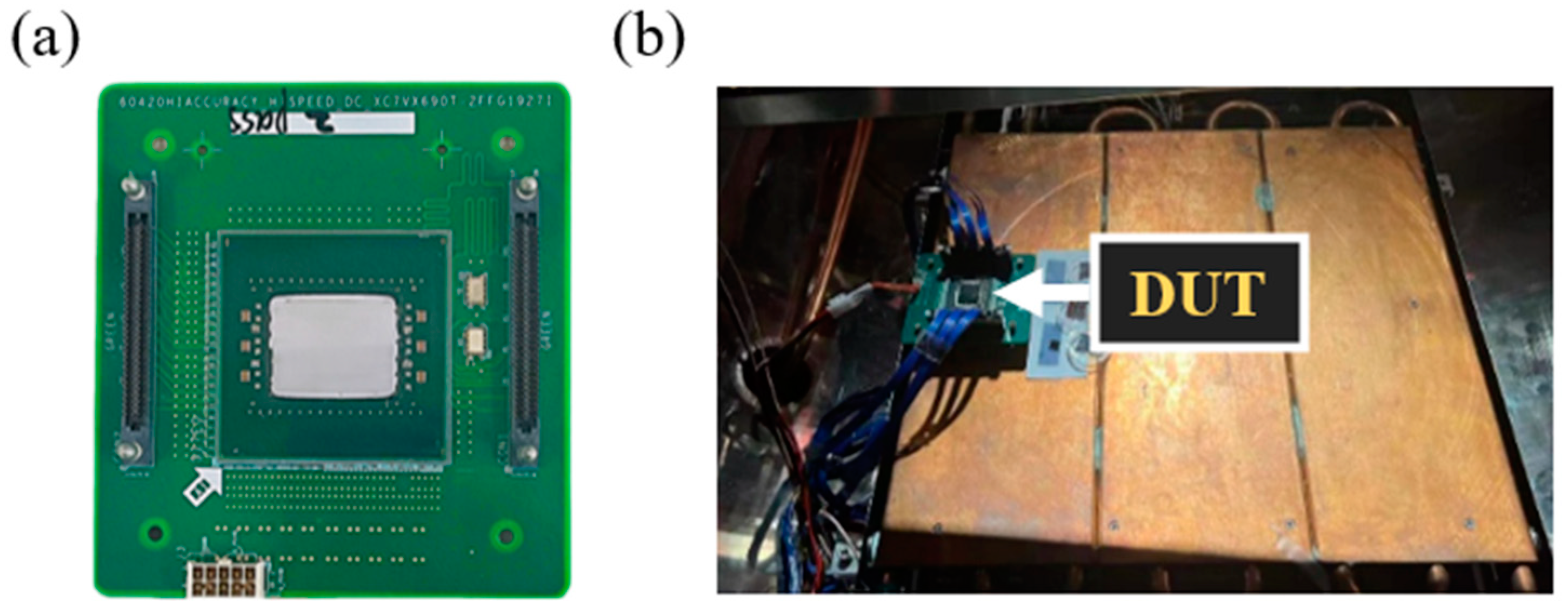
Figure 1. The 28 nm FPGA installed in the electron irradiation chamber. (a) Device under test, (b) experimental setup.
Electronics 13 02233 g001
Figure 2. SEE test system for DUT.
Electronics 13 02233 g002
Figure 3. Geometric model of POR used in Geant4 simulation.
Electronics 13 02233 g003
Figure 4. LET distribution ratio for different electron energies.
Electronics 13 02233 g004
Figure 5. Characteristics curves of 28 nm bulk MOSFET. (a) Structures of 28 nm NMOS; (b) NMOS transfer characteristic curve; (c) Structures of 28 nm PMOS; (d) PMOS transfer characteristic curve.
Electronics 13 02233 g005
Figure 6. Drain transient current at different LET values.
Electronics 13 02233 g006
Figure 7. Fault injection in POR register. The inset indicates the fault injection nodes.
Electronics 13 02233 g007
Figure 8. SPICE simulation results when the fault is injected into different nodes. The red boxes indicate the DONE state of each fault injection node under different LET values.
Electronics 13 02233 g008
Table 1. Summary of the experimental results in the 28 nm FPGA.
Electron Energy
(MeV)
Fluence
(cm−2)
Recorded SELsRecorded SEFIsRecorded SEUs
PORSMAPCLBBRAM
1 1 × 10 12 NONEPASSPASS00
2 1 × 10 12 NONEPASSPASS00
3 1 × 10 12 NONEFAILPASS28,671,3731,760,000
4 1 × 10 12 NONEPASSPASS00
5 1 × 10 12 NONEPASSPASS00
Table 2. Process parameters of 28 nm bulk MOS devices.
ParametersValue
Channel length/nm28
Thickness of gate oxide (SiO2)/nm2
Channel doping/cm−31 × 1016
Source/drain doping/cm−34 × 1020
Substrate doping/cm−33 × 1018
Disclaimer/Publisher’s Note: The statements, opinions and data contained in all publications are solely those of the individual author(s) and contributor(s) and not of MDPI and/or the editor(s). MDPI and/or the editor(s) disclaim responsibility for any injury to people or property resulting from any ideas, methods, instructions or products referred to in the content.