


Folded Narrow-Band and Wide-Band Monopole Antennas with In-Plane and Vertical Grounds for Wireless Sensor Nodes in Smart Home IoT Applications


Abstract
1. Introduction
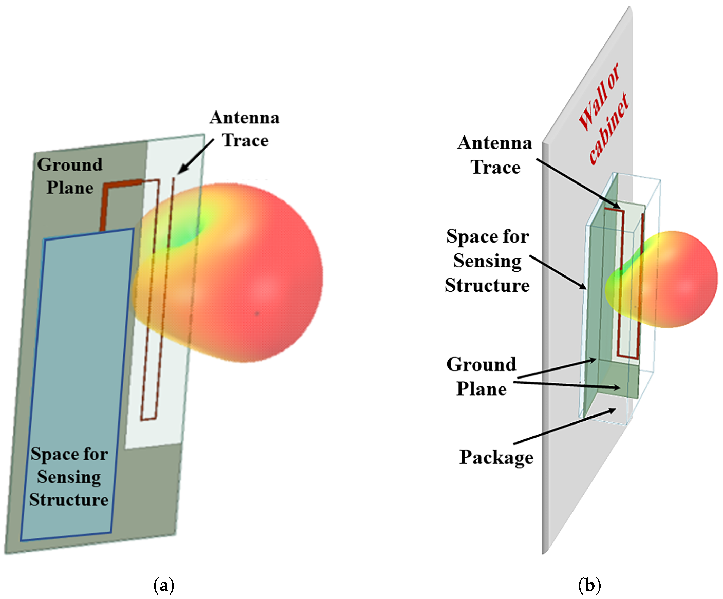
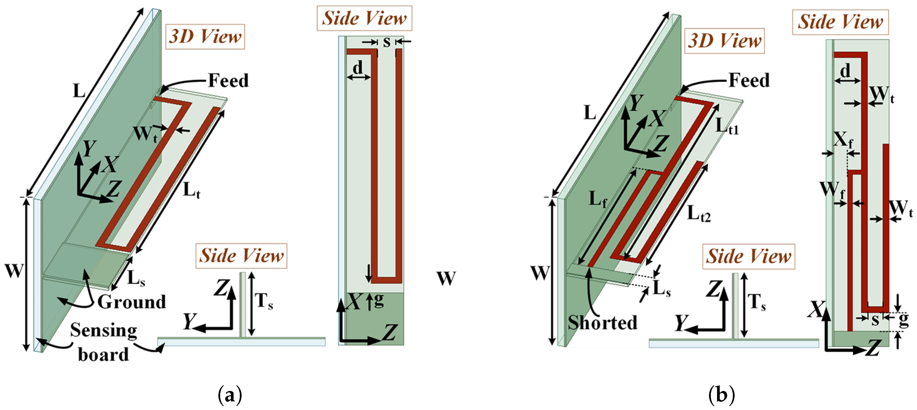
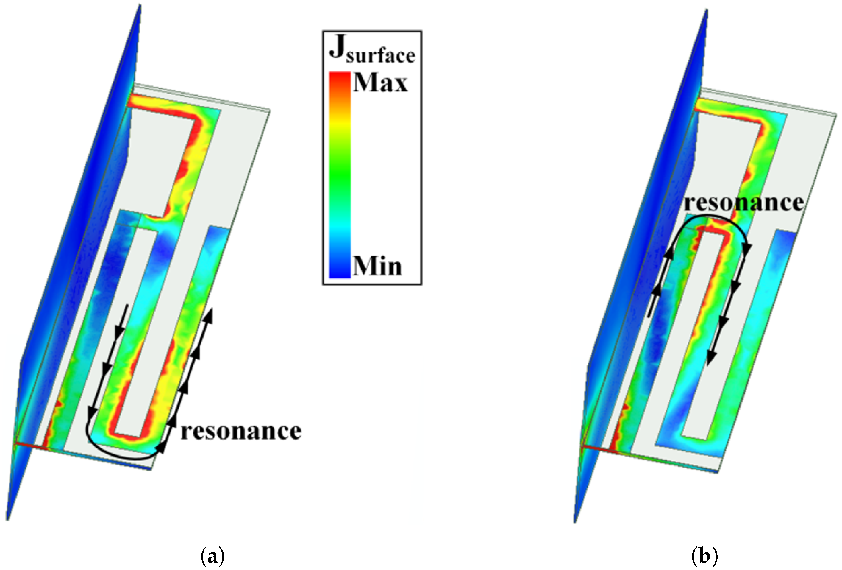
2. Antenna Design
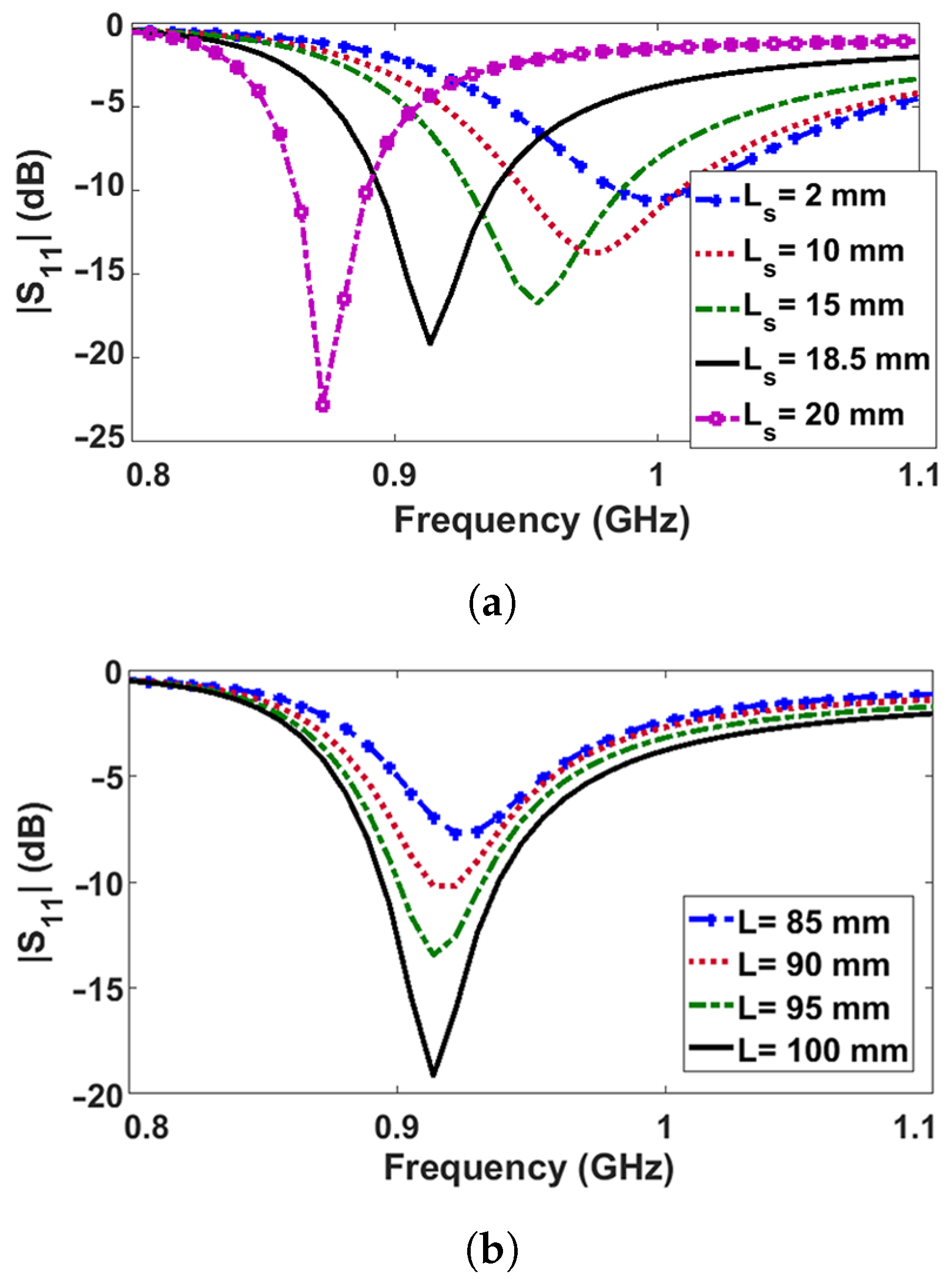
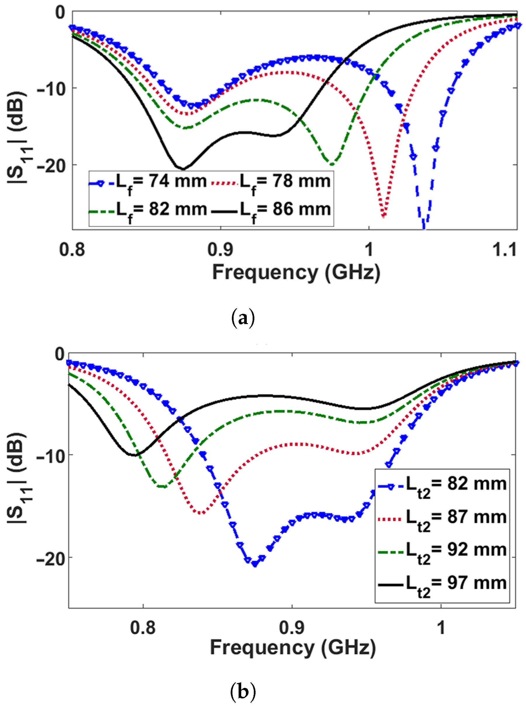
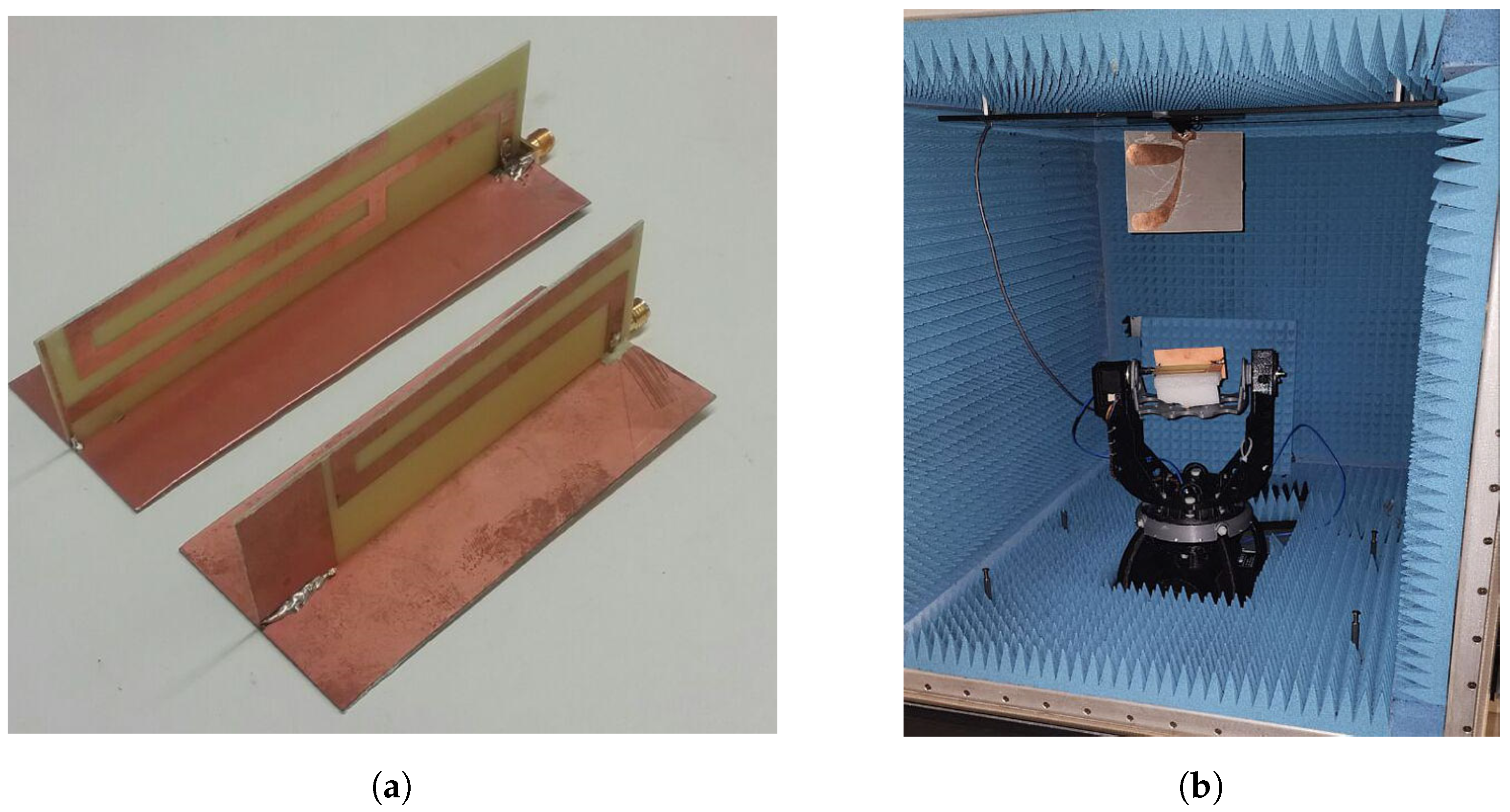
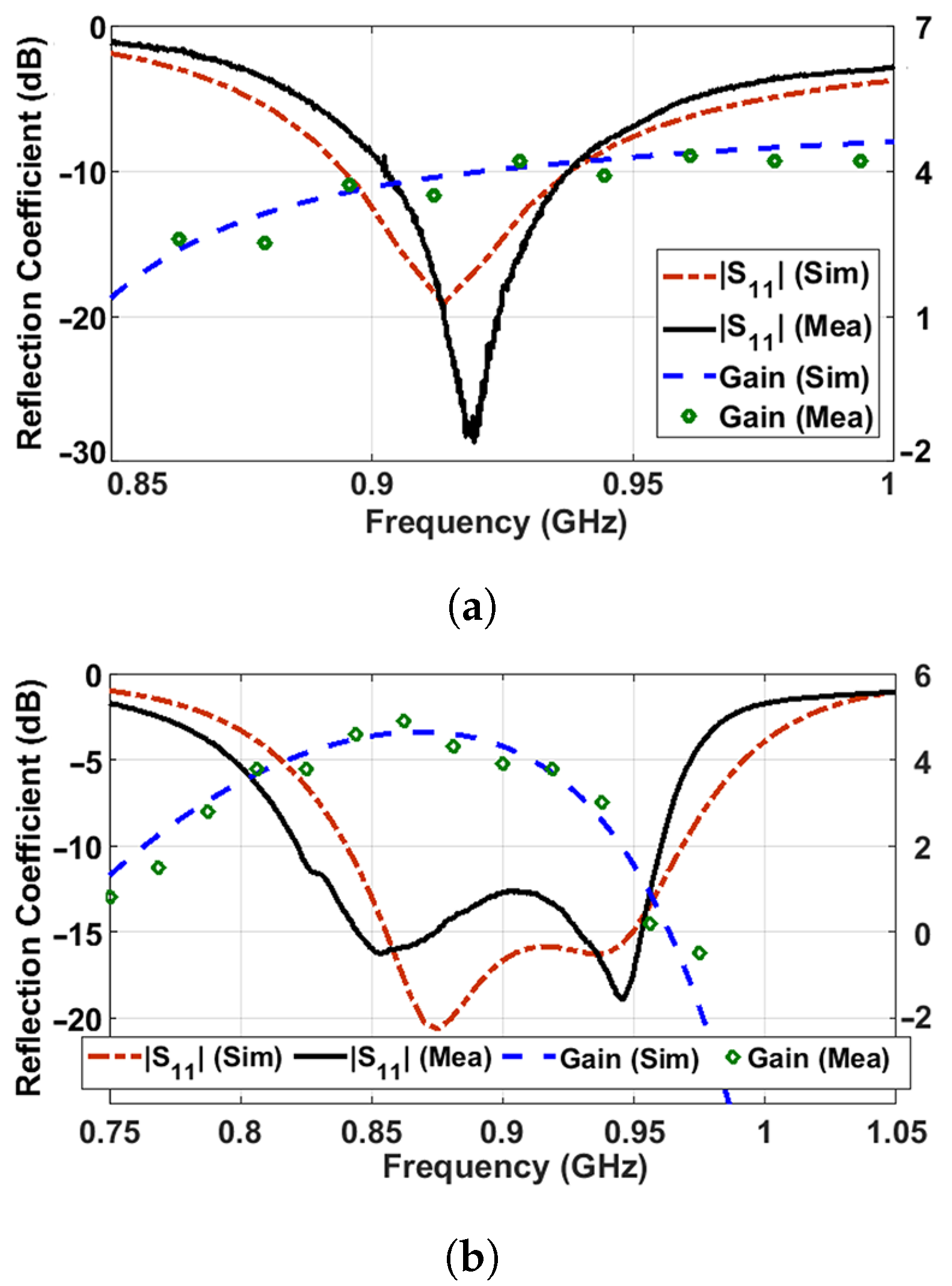
3. Experimental Results and Discussion
4. Conclusions
Author Contributions
Funding
Data Availability Statement
Conflicts of Interest
References
- Saghlatoon, H.; Mirzavand, R.; Honari, M.M.; Mousavi, P. Sensor Antenna Transmitter System for Material Detection in Wireless-Sensor-Node Applications. IEEE Sens. J. 2018, 21, 8812–8819. [Google Scholar] [CrossRef]
- Liu, H.; Cheng, Y.; Yan, M. Electrically Small Loop Antenna Standing on Compact Ground in Wireless Sensor Package. IEEE Antennas Wirel. Propag. Lett. 2016, 64, 76–79. [Google Scholar] [CrossRef]
- Varnoosfaderani, M.V.; Thiel, D.V.; Lu, J.W. A Wideband Slot Antenna in a Box for Wearable Sensor Nodes. IEEE Antennas Wirel. Propag. Lett. 2015, 14, 1494–1497. [Google Scholar] [CrossRef]
- Wu, T.; Li, R.; Tentzeris, M.M. A Scalable Solar Antenna for Autonomous Integrated Wireless Sensor Nodes. IEEE Antennas Wirel. Propag. Lett. 2011, 10, 510–513. [Google Scholar] [CrossRef]
- Khalid, N.; Iyer, A.K.; Mirzavand, R. A Batteryless Six-Port RFID-Based Wireless Sensor Architecture for IoT Applications. IEEE Internet Things J. 2022, 9, 18550–18558. [Google Scholar] [CrossRef]
- Solar, H.; Beriain, A.; Rezola, A.; del Rio, D.; Berenguer, R. A 22-m Operation Range Semi-Passive UHF RFID Sensor Tag with Flexible Thermoelectric Energy Harvester. IEEE Sens. J. 2022, 22, 19797–19808. [Google Scholar] [CrossRef]
- Sriram, V.P.; Raj, K.B.; Srinivas, K.; Pallathadka, H.; Sajja, G.S.; Gulati, K. An Extensive Systematic Review of RFID Technology Role in Supply Chain Management. In Proceedings of the International Conference on Signal Processing, Computing and Control (ISPCC), Solan, India, 7–9 October 2021; pp. 789–794. [Google Scholar]
- Zhang, S.; Liu, X.; Liu, Y.; Ding, B.; Guo, S.; Wang, J. Accurate Respiration Monitoring for Mobile Users with Commercial RFID Devices. IEEE J. Sel. Areas Commun. 2021, 39, 513–525. [Google Scholar] [CrossRef]
- Zhang, K.; Amineh, R.K.; Dong, Z.; Nadler, D. Microwave Sensing of Water Quality. IEEE Access 2019, 7, 69481–69493. [Google Scholar] [CrossRef]
- Lehpamer, H. RFID Design Principles; Artech House: Norwood, MA, USA, 2007. [Google Scholar]
- Saghlatoon, H.; Mirzavand, R.; Honari, M.M.; Mousavi, P. Investigation on Passive Booster for Improving Magnetic Coupling of Metal Mounted Proximity Range HF RFIDs. IEEE Trans. Microw. Theory Tech. 2017, 65, 3401–3408. [Google Scholar] [CrossRef]
- Görtschacher, L.J.; Amtmann, F.; Muehlmann, U.; Merlin, E.; Priller, P.; Grosinger, J. Passive HF RFID Repeater for Communicating with Tags in Metal Housings. IEEE Antennas Wirel. Propag. Lett. 2020, 19, 1625–1629. [Google Scholar] [CrossRef]
- Khalid, N.; Mirzavand, R.; Saghlatoon, H.; Honari, M.M.; Mousavi, P. A Three-Port Zero-Power RFID Sensor Architecture for IoT Applications. IEEE Access 2020, 8, 66888–66897. [Google Scholar] [CrossRef]
- Alibakhshikenari, M.; Virdee, B.S.; Althuwayb, A.A.; Xu, K.D.; See, C.H.; Khan, S.; Park, I.; Falcone, F.; Limiti, E. Novel concentric hexagonal-shaped RFID tag antenna with T-shaped stub matching. IEEE J. Radio Freq. Identif. 2021, 6, 112–120. [Google Scholar] [CrossRef]
- Basit, A.; Khattak, M.I.; Althuwayb, A.; Nebhen, J. Compact tri-band bandpass filter based on asymmetric step impedance resonators for WiMAX and RFID systems. J. Electromagn. Eng. Sci. 2021, 21, 316–321. [Google Scholar] [CrossRef]
- Abdulhadi, A.E.; Abhari, R. Design and experimental evaluation of miniaturized monopole UHF RFID tag antennas. IEEE Antennas Wirel. Propag. Lett. 2012, 13, 248–251. [Google Scholar] [CrossRef]
- Tan, J.I.; Lee, Y.H.; Lim, E.H.; Bong, F.L.; Chung, B.K. A Low-Profile Top-Loaded Monopole Antenna for On-Metal RFID Tag Design. IEEE J. Radio Freq. Identif. 2024, 8, 448–457. [Google Scholar] [CrossRef]
- Aggarwal, I.; Tripathy, M.R.; Pandey, S.; Mittal, A. A Dual band Monopole Antenna For RFID Applications. In Proceedings of the 2021 IEEE International Conference on RFID Technology and Applications (RFID-TA), Delhi, India, 6–8 October 2021; pp. 67–70. [Google Scholar]
- Asci, C.; Wang, W.; Sonkusale, S. Security Monitoring System Using Magnetically-Activated RFID Tags; IEEE: Rotterdam, The Netherlands, 2020; pp. 1–4. [Google Scholar]
- Wang, Y.; Yan, S. A Compact In-Band Full Duplexing Antenna with Quasi-Isotropic Radiation Pattern for IoT-Based Smart Home and Intravehicle Wireless Communication Applications. IEEE Internet Things J. 2022, 9, 16689–16700. [Google Scholar] [CrossRef]
- Khalili, H.F.; Lemey, S.; Caytan, O.; Deckmyn, T.; Agneessens, S.; Ginste, D.V.; Rogier, H. Biodegradable Dual Semicircular Patch Antenna Tile for Smart Floors. IEEE Antennas Wirel. Propag. Lett. 2019, 18, 368–372. [Google Scholar] [CrossRef]
- Hu, Z.; Shen, Z.; Wu, W.; Lu, J. Low-Profile Top-Hat Monopole Yagi Antenna for End-Fire Radiation. IEEE Trans. Antennas Propag. 2015, 63, 2851–2857. [Google Scholar] [CrossRef]
- Zhang, X.; Sun, F.; Zhang, G.; Hou, L. Compact UHF/VHF Monopole Antennas for CubeSats Applications. IEEE Access 2020, 8, 133360–133366. [Google Scholar] [CrossRef]
- Zheng, M.; Wang, H.; Hao, Y. Internal Hexa-Band Folded Monopole/Dipole/Loop Antenna with Four Resonances for Mobile Device. IEEE Trans. Antennas Propag. 2012, 60, 2880–2885. [Google Scholar] [CrossRef]
- Li, Y.; Podilchak, S.K.; Anagnostou, D.E.; Constantinides, C.; Walkinshaw, T. Compact Antenna for Picosatellites Using a Meandered Folded-Shorted Patch Array. IEEE Antennas Wirel. Propag. Lett. 2020, 19, 477–481. [Google Scholar] [CrossRef]
- Zhang, H.; Li, M.; Yang, F.; Xu, S.; Zhou, H.; Yang, Y.; Chen, L. A Low-Profile Compact Dual-Band L-Shape Monopole Antenna for Microwave Thorax Monitoring. IEEE Antennas Wirel. Propag. Lett. 2020, 19, 448–452. [Google Scholar] [CrossRef]
- Abdulhadi, A.E.; Abhari, R. Passive UHF RFID printed monopole tag antenna for identification of metallic objects. In Proceedings of the 2012 IEEE International Symposium on Antennas and Propagation, Chicago, IL, USA, 8–14 July 2012; pp. 1–2. [Google Scholar]
- Ramirez, R.A.; Rojas-Nastrucci, E.A.; Weller, T.M. UHF RFID tags for on-/off-metal applications fabricated using additive manufacturing. IEEE Antennas Wirel. Propag. Lett. 2017, 16, 1635–1638. [Google Scholar] [CrossRef]
- Hussain, M.; Amin, Y.; Lee, K.G. A compact and flexible UHF RFID tag antenna for massive IoT devices in 5G system. Sensors 2020, 20, 5713. [Google Scholar] [CrossRef]
- Zhao, L.; Ma, Y.; Meng, W.; Peng, K.; Liu, K. Bendable folded-patch antenna with resonant ring manufactured based on foam support and PET substrate for on-metal UHF RFID. IEEE J. Radio Freq. Identif. 2023, 7, 591–600. [Google Scholar] [CrossRef]


| References | Antenna Type | Antenna Size mm2 | Radiation Pattern | Radiation Efficiency (%) | Realized Gain (dBi) |
|---|---|---|---|---|---|
| our work | Monopole | 100 × 48 | Directional | 95 | 4 |
| [27] | Monopole | 83.625 × 83.625 | Directional | 76 | 2.7 |
| [28] | Monopole | 98.75 × 57 | Omnidirectional | N/A | 3.2 |
| [29] | Dipole | 101.2 × 10.5 | Omnidirectional | N/A | 3.14 |
| [30] | Patch | 50 × 50 | Directional | N/A | −5.4 |
Disclaimer/Publisher’s Note: The statements, opinions and data contained in all publications are solely those of the individual author(s) and contributor(s) and not of MDPI and/or the editor(s). MDPI and/or the editor(s) disclaim responsibility for any injury to people or property resulting from any ideas, methods, instructions or products referred to in the content. |
© 2024 by the authors. Licensee MDPI, Basel, Switzerland. This article is an open access article distributed under the terms and conditions of the Creative Commons Attribution (CC BY) license (https://creativecommons.org/licenses/by/4.0/).
Share and Cite
Honari, M.M.; Javadi, S.P.; Mirzavand, R. Folded Narrow-Band and Wide-Band Monopole Antennas with In-Plane and Vertical Grounds for Wireless Sensor Nodes in Smart Home IoT Applications. Electronics 2024, 13, 2262. https://doi.org/10.3390/electronics13122262
Honari MM, Javadi SP, Mirzavand R. Folded Narrow-Band and Wide-Band Monopole Antennas with In-Plane and Vertical Grounds for Wireless Sensor Nodes in Smart Home IoT Applications. Electronics. 2024; 13(12):2262. https://doi.org/10.3390/electronics13122262
Chicago/Turabian StyleHonari, Mohammad Mahdi, Seyed Parsa Javadi, and Rashid Mirzavand. 2024. "Folded Narrow-Band and Wide-Band Monopole Antennas with In-Plane and Vertical Grounds for Wireless Sensor Nodes in Smart Home IoT Applications" Electronics 13, no. 12: 2262. https://doi.org/10.3390/electronics13122262
APA StyleHonari, M. M., Javadi, S. P., & Mirzavand, R. (2024). Folded Narrow-Band and Wide-Band Monopole Antennas with In-Plane and Vertical Grounds for Wireless Sensor Nodes in Smart Home IoT Applications. Electronics, 13(12), 2262. https://doi.org/10.3390/electronics13122262