Article

Sliding-Mode Control of Linear Induction Motor Based on Exponential Reaching Law

School of Electrical Engineering, Naval University of Engineering, Wuhan 430030, China
*
Author to whom correspondence should be addressed.
Electronics 2024, 13(12), 2352; https://doi.org/10.3390/electronics13122352
Submission received: 8 April 2024 / Revised: 29 May 2024 / Accepted: 13 June 2024 / Published: 15 June 2024
(This article belongs to the Section Power Electronics)

Abstract

:
As a strongly coupled, multivariable, high-order nonlinear, time-varying complex system, a linear induction motor is susceptible to outside disturbances and mismatched parameters. Because of its straightforward control mechanism and fixed PI value, the traditional PI regulator is frequently utilized in linear induction motor speed control systems. However, because of these limitations, it frequently falls short of meeting the high-performance control needs of the motor in complex operating conditions. In order to solve the contradiction between the sliding-mode motion reaching time and vibration, the sliding-mode variable structure control is applied to the linear induction motor speed control system in this paper. The sliding-mode controller is designed using the exponential reaching law method, and the designed system is analyzed through simulation. The findings demonstrate how the controller enhances the system’s robustness and disturbance resistance by bringing about the advantages of rapidity, stability, no overshooting, and a strong resistance to load disturbance.

1. Introduction

Linear induction motors (LIM) have been widely used in the electromagnetic ejection systems of naval aircraft, urban rail transportation (e.g., AirTrain in Canada, JFK Airlines in the U.S., Ode Line in Japan, Guangzhou Metro Lines 4, 5, and 6, and Changsha low-speed magnetic levitation (MLF) line) [1], passenger terminal personnel transportation (e.g., at the Dallas Fort Worth International Airport) [2], and electrically operated gates due to their unique linear type of motion [3].
Nevertheless, LIMs are complex objects with variable parameters that are multivariable, strongly coupled, and nonlinear. Although it can meet control requirements within a certain range when using traditional proportion integration differentiation (PID) controls, the motor’s performance in complex working conditions is not limited by its application occasions because it depends on an accurate model of LIM, which is highly susceptible to external perturbations and parameter mismatches. This makes it difficult to obtain satisfactory speed regulation and positioning performance [4,5].
Motor operating performance can be effectively enhanced by modern control theories like model-referenced adaptive control, fuzzy control, and neural network control [6,7]. However, the model-referenced adaptive control’s anti-disturbance performance is insufficient to meet the control requirements of real-world scenarios; the fuzzy control’s effect is less than ideal due to the interaction of complex fuzzy rules; and the neural network controller necessitates a very fast digital processor due to its requirement for constantly learning how to adjust the parameters.
Two Soviet researchers, S.V. Emelyanov and V.I. Utkin [8,9], introduced the sliding-mode variable-structure control in the 1950s, which has the benefits of strong immunity and robustness. Discontinuity, which typically consists of a sliding-mode surface and a sliding-mode controller, is the primary distinction between sliding-mode control and conventional nonlinear control techniques. During the arrival phase, which has a finite duration, the sliding-mode controller drives the system state to the sliding-mode surface. The system state is thus compelled to travel along the surface of the sliding mode until it converges to zero, or the sliding phase.
The use of the sliding-mode variable-structure control (SMC) for linear induction motor control is currently poorly documented. In order to address the issue of sensitivity to uncertainties during the operation of permanent magnet linear synchronous motors, such as system parameter mismatch and end effects, ref. [10] designed a fixed boundary layer sliding-mode controller using a feedback linearized msat function; while [11], in order to solve the contradiction between the tracking performance of the system of permanent magnet linear synchronous motors and the robust performance, proposed a combination of the H robust control and the sliding-mode control for the permanent magnet synchronous linear motor’s robust tracking control strategy.
In order to effectively counter the centralized uncertainty of the LIM drive, ref. [12] proposed a sliding-mode controller embedded with a workable fuzzy compensator based on a backstepping control design. However, because of hysteresis in the area where the switching devices are located, the switching delays of the devices, and the features of the discrete system itself, the sliding-mode variable structure control is susceptible to the jitter phenomenon when applied to a real system, which is highly detrimental to the electromechanical system.
Higher-order sliding-mode [13] and intelligent sliding-mode control [14], and convergence law [15,16] are now the main techniques for suppressing jitter; however, in this study, jitter is suppressed from the standpoint of convergence law. There are numerous common convergence laws in use today, including general convergence law, exponential convergence law, idempotent convergence law, and isochronous convergence law. In comparison to pure isochronous convergence, the exponential convergence law shortens the convergence time by accelerating the speed of convergence and containing both an isochronous and an exponential convergence term, which are superposed to zero during the convergence motion stage, which ensures the arrival in a finite amount of time because it is not an asymptotic convergence, in contrast with pure exponential convergence.
Related research has demonstrated that this method has been effectively used in the domains of power factor correction, electric power systems, and switched reluctance motor control [17,18,19], but it is not as commonly used with linear induction motors.
To enhance the speed control system’s anti-interference performance, a permanent magnet synchronous motor speed controller based on a super-helical sliding-mode algorithm was proposed in [20]. In addition, ref. [21] adjusted the higher-order sliding-mode controller’s gain online using an adaptive law to lower the system jitter. In [22], a higher-order sliding-mode observer is constructed to simultaneously observe the motor speed and load torque. This improves the motor’s dynamic performance and lessens the negative impact of encoder measurement noise. In [23], by utilizing fuzzy logic rules to modify the terminal sliding-mode controller’s gain online, an adaptive fuzzy terminal sliding-mode controller is put forth. In order to achieve accurate tracking control of the motor’s speed loop under load perturbations and electromagnetic disturbances, this paper has designed a sliding-mode controller for linear induction motors based on the exponential reaching law. The goal is to address the poor control performance of linear induction motors under the influence of parameter mismatch and external perturbations.
The paper is structured as follows: Section 2 provides the mathematical model of the linear induction motor in the dq coordinate system. Next, in Section 3, the exponential convergence law-based SMC speed controller is established. The simulation results of loading and unloading under SMC and PI, as well as acceleration and deceleration, are provided and discussed in Section 4 in order to validate the suggested control method. Section 5 concludes with some final thoughts.

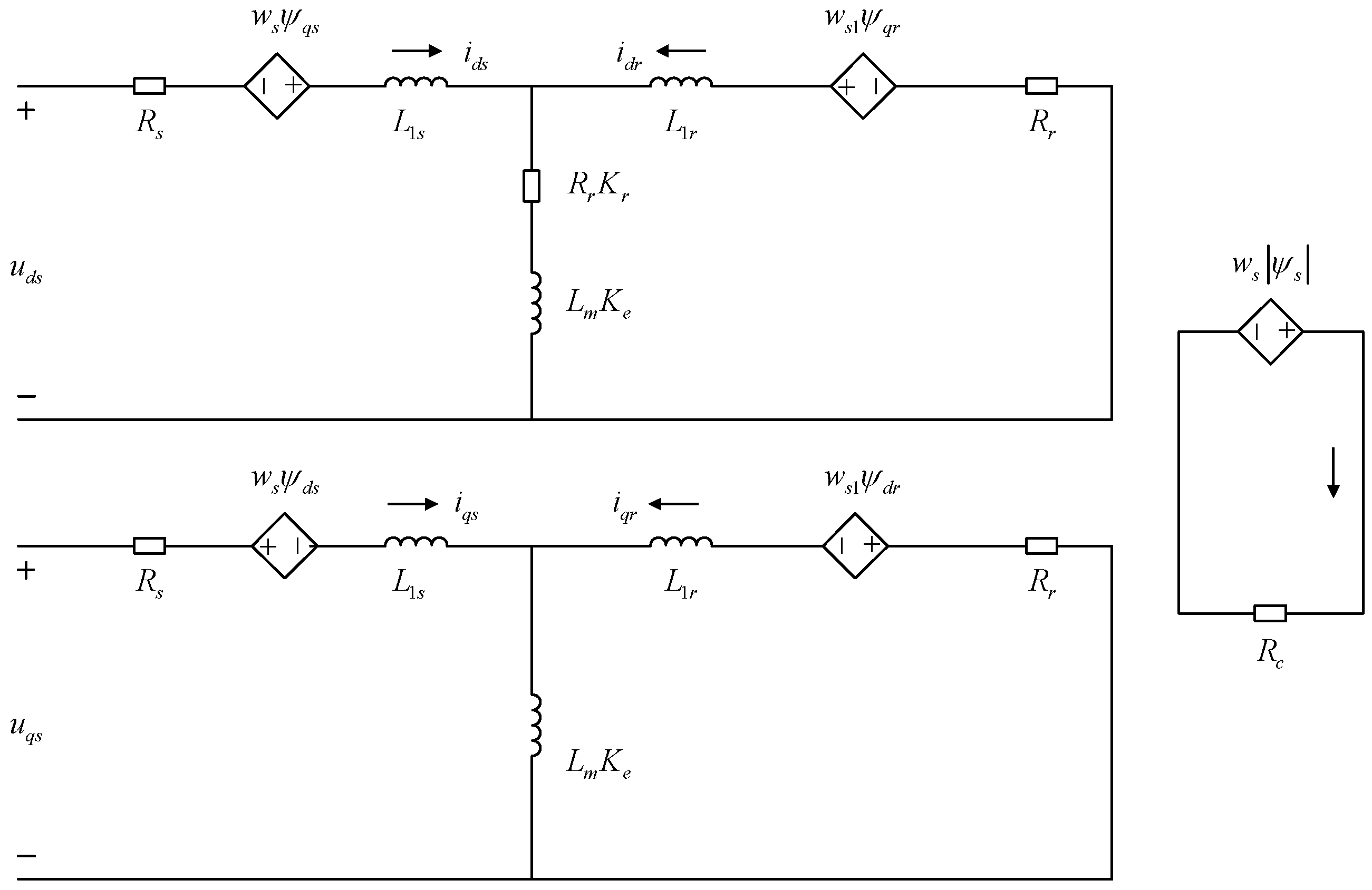
2. Mathematical Modeling of Linear Induction Motors

The iron loss resistor is typically connected in parallel next to the excitation branch in order to simplify the analysis because the rotary inductance motors (RIM) leakage inductance is very small [24]. This simplified analysis will not result in a significant error in the model. In contrast with the excitation inductance, the primary leakage inductance of the LIM with a large air gap is significant and cannot be ignored.
Following the generalized Clarke transform [25,26] to obtain the mathematical model in the α–β subplane involving only the electromechanical energy conversion, and then rotational transformation to obtain the equivalent dc motor model in the d–q subplane, Figure 1 shows the equivalent circuit of the LIM, taking into account the edge effect and iron dissipation resistance. The transformation matrix is shown in the Appendix A as Equations (A1) and (A2). Table A1 of Appendix A displays the symbols’ meanings that are mentioned in this equivalent circuit [27].
This is equivalent to shunting the excitation inductance by connecting an inductor in parallel with the LIM excitation circuit. The model starts with the Q coefficient of the Duncan model, and the secondary guide plate eddy current generates a magnetic field that partially offsets the motor air gap magnetic field. Ke and Kr, which are the excitation inductance attenuation coefficient and secondary eddy current loss coefficient, respectively, are derived in this manner; the specific expressions are provided in the Appendix A equations as Equations (A3)–(A5).
Consequently, the following is an appropriate way to write the asymmetric equivalent circuit voltage and flux equations of the LIM:
u ds = i ds R s + p ψ ds ω s ψ qs + ( i ds + i dr ) R r K r u qs = i qs R s + p ψ qs + ω s ψ ds 0 = i dr R r + p ψ dr ω sl ψ qr + ( i ds + i dr ) R r K r 0 = i qr R r + p ψ qr + ω sl ψ dr
ψ ds = L ls i ds + L m K e ( i ds + i dr ) ψ qs = L ls i qs + L m K e ( i qs + i qr ) ψ dr = L lr i dr + L m K e ( i ds + i dr ) ψ qr = L lr i qr + L m K e ( i qs + i qr )
The thrust equation based on secondary flux orientation can be written as follows:
F = β L me ( i dr i qs i qr i ds ) = β L me L me + L lr ψ dr i qs
where p is the differential operator, β = π/τ. To simplify the expression below, let Lme = LmKe, Rre = RrKr, k T = β L me L me + L lr ψ dr .
The mechanical equation of motion is as follows:
F F l = m d v d t + B v
where F, Fl, B and m are the electromagnetic thrust, load, system viscosity coefficient, and traction weight of the linear induction motor, respectively.

3. Sliding-Mode Controllers

3.1. Design for Reaching Law

The general sliding-mode control only takes into account the ability to converge to the sliding-mode surface and satisfy the stability conditions; the stability conditions do not account for the manner in which the motion converges to the sliding-mode surface. The sliding-mode variable structure control process is divided into two phases, normal motion and sliding mode. The reaching law method can better ensure the quality of the normal motion phase, and the appropriate design of the reaching law can be used away from the switching surface, where the speed of the motion point tends to be large in order to accelerate the dynamic response of the system. Furthermore, upon the convergence with the switching surface, the speed decreases asymptotically to zero, in order to weaken the shivering vibration.
The exponential reaching law method is better able to attenuate the sliding-mode jitter, and it is simpler and more intuitive to find u. It takes the following form:
s ˙ = ε sgn ( s ) k s
where ε and k are constants greater than zero, s represents the sliding variable.
Equation (5) with s > 0 would be as follows:
s ˙ = ε k s
Assuming the initial value of the sliding mold surface is s0, the conventional expression for s(t) can be obtained by solving the following mathematical formula:
s ( t ) = ε k + s 0 + ε k e k t
It can be seen that in the exponential reaching law the rate of convergence is faster than the exponential law when t is sufficiently large.
When s > 0 and s(t) = 0, there are the following:
ε k = s 0 + ε k e k t ln ε k ln s 0 + ε k = k t
From this, the following can be sought:
t = 1 k ln ( s 0 + ε k ) ln ε k
It is evident that the system has a finite amount of time to travel from the initial state to the sliding-mode surface. The engineering application takes into account the combination of the coefficient k and the change in the actual system state quantity. The parameter k influences the time it takes to reach the sliding-mode surface. Increasing k can speed up response times, but doing so will result in an excessive tendency toward the sliding-mode surface.

3.2. Stabilization Analysis

Take the state variables of the LIM system as follows:
x 1 = v v x 2 = x ˙ 1 = v ˙
where v* is the given speed, v the actual speed. x1 is the velocity error, v* is the reference speed of the motor, which is usually a constant, and v is the actual motor speed.
Combining this with Equation (4) gives the following:
x ˙ 1 = v ˙ = 1 m k T i q s B v F l x ˙ 2 = v ¨ = k T m i ˙ q s
The state space of the system can be obtained using the following:
x ˙ 1 x ˙ 2 = 0 1 0 0 x 1 x 2 + 0 k T m i ˙ q s
The sliding-mode surface is as follows:
s = c x 1 + x 2
where c is the sliding-mode gain coefficient to be designed. The derivation for s is obtained using the following:
s ˙ = c x ˙ 1 + x ˙ 2 = c x 2 + x ˙ 2 = c x 2 k T m i ˙ q s
The choice of limiting the exponential reaching law method in the s-form, when finding the control quantity, is made possible with a combination of Equations (5) and (14) as follows:
ε sgn ( s ) k s = c x 2 k T m i ˙ q s
The expression for the control quantity iqs can be obtained from Equation (16) as follows:
i q s = m k T c x 2 + ε sgn ( s ) + k s d t
The Lyapunov function is chosen as V = 1/2*s2, and from the Lyapunov stability theory, the stability of the system controlled by the sliding-mode needs to satisfy the following conditions:
V ˙ c = s s ˙ = s ( ε sgn ( s ) k s ) lim s 0 V ˙ c < 0
where ε, k are constants greater than zero, ensuring that s is different from the isosign. According to the Lyapunov stability theory, it can be seen that the system satisfies the stability conditions, proving that the system under the control of this reaching law sliding-mode is stable.

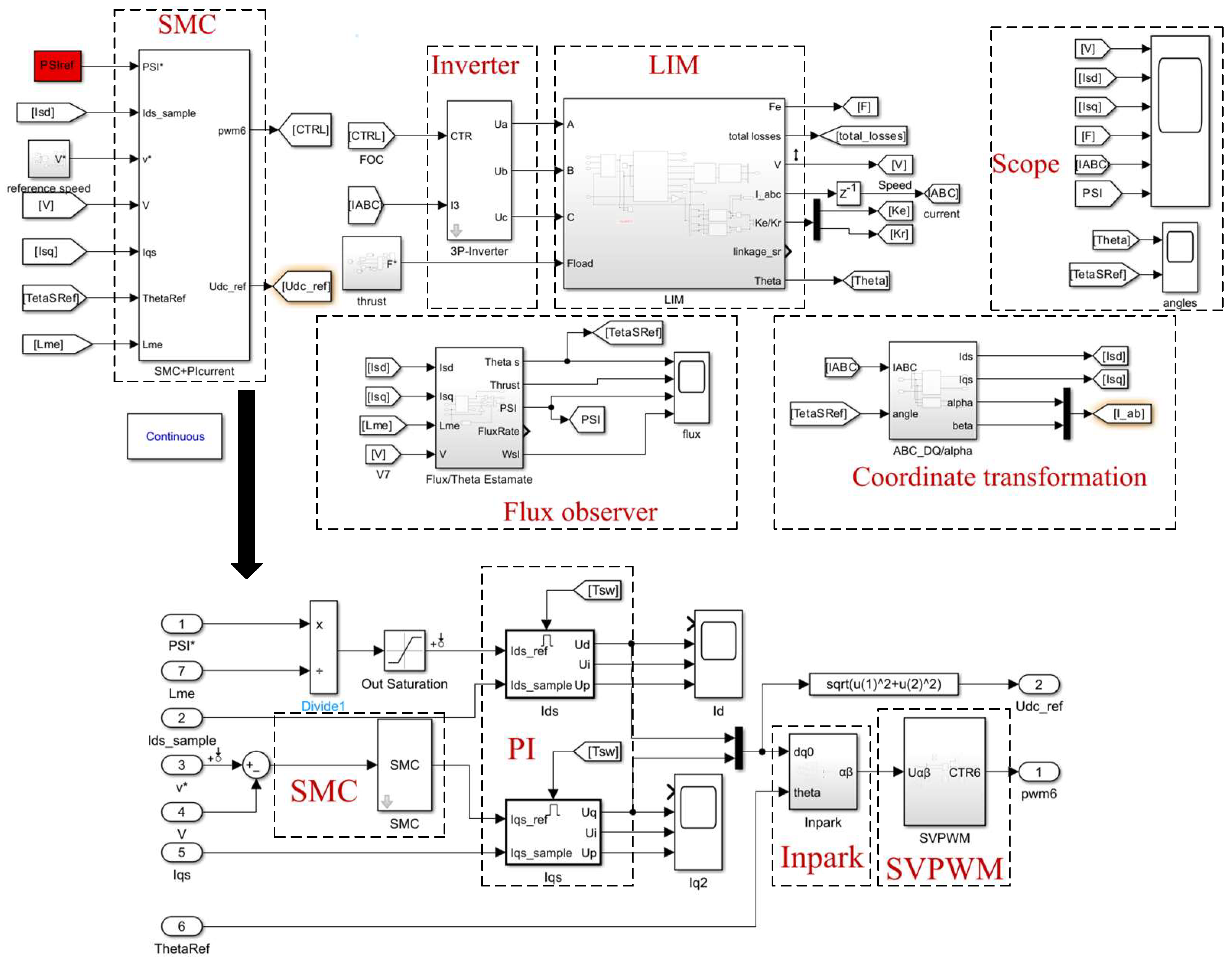
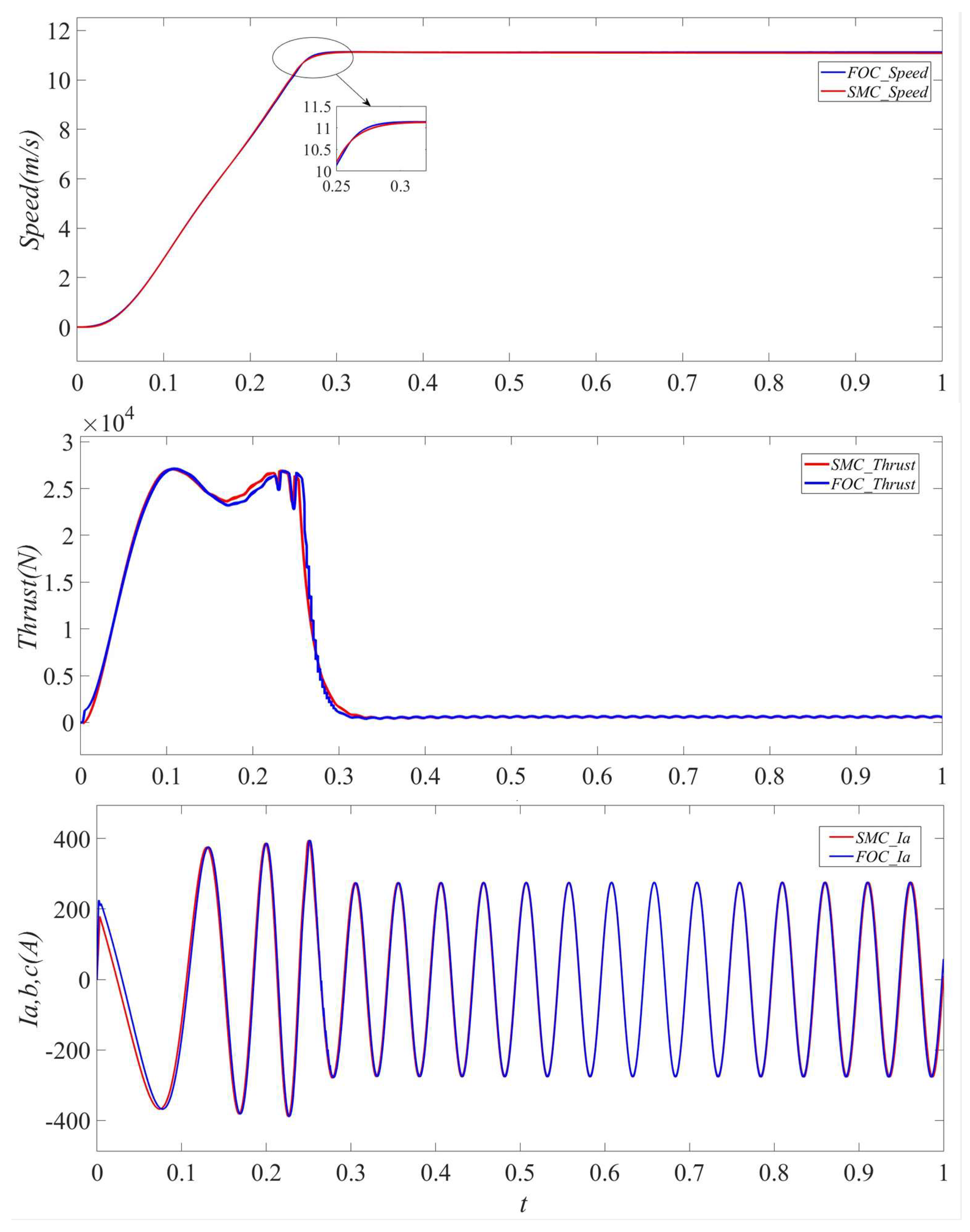
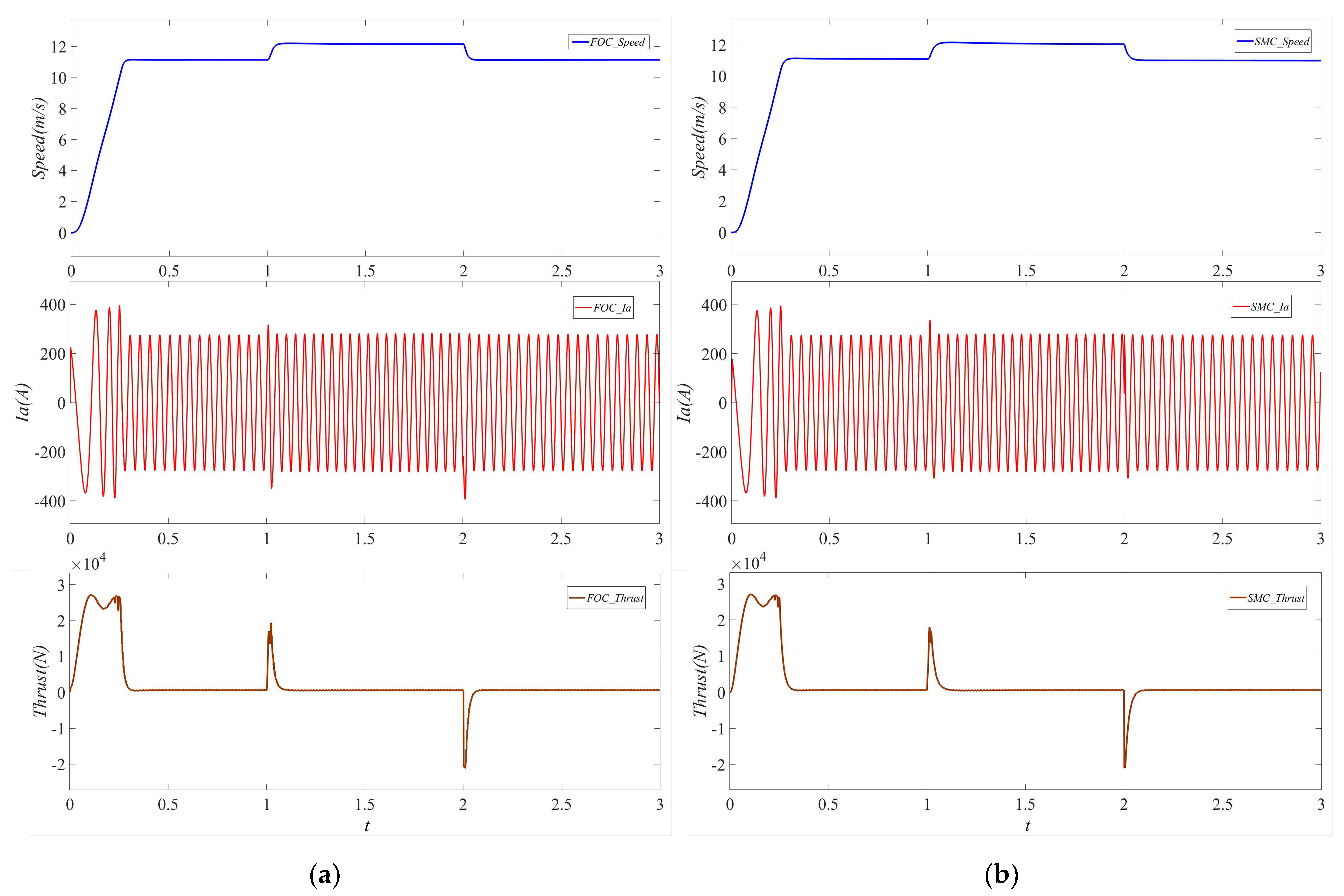
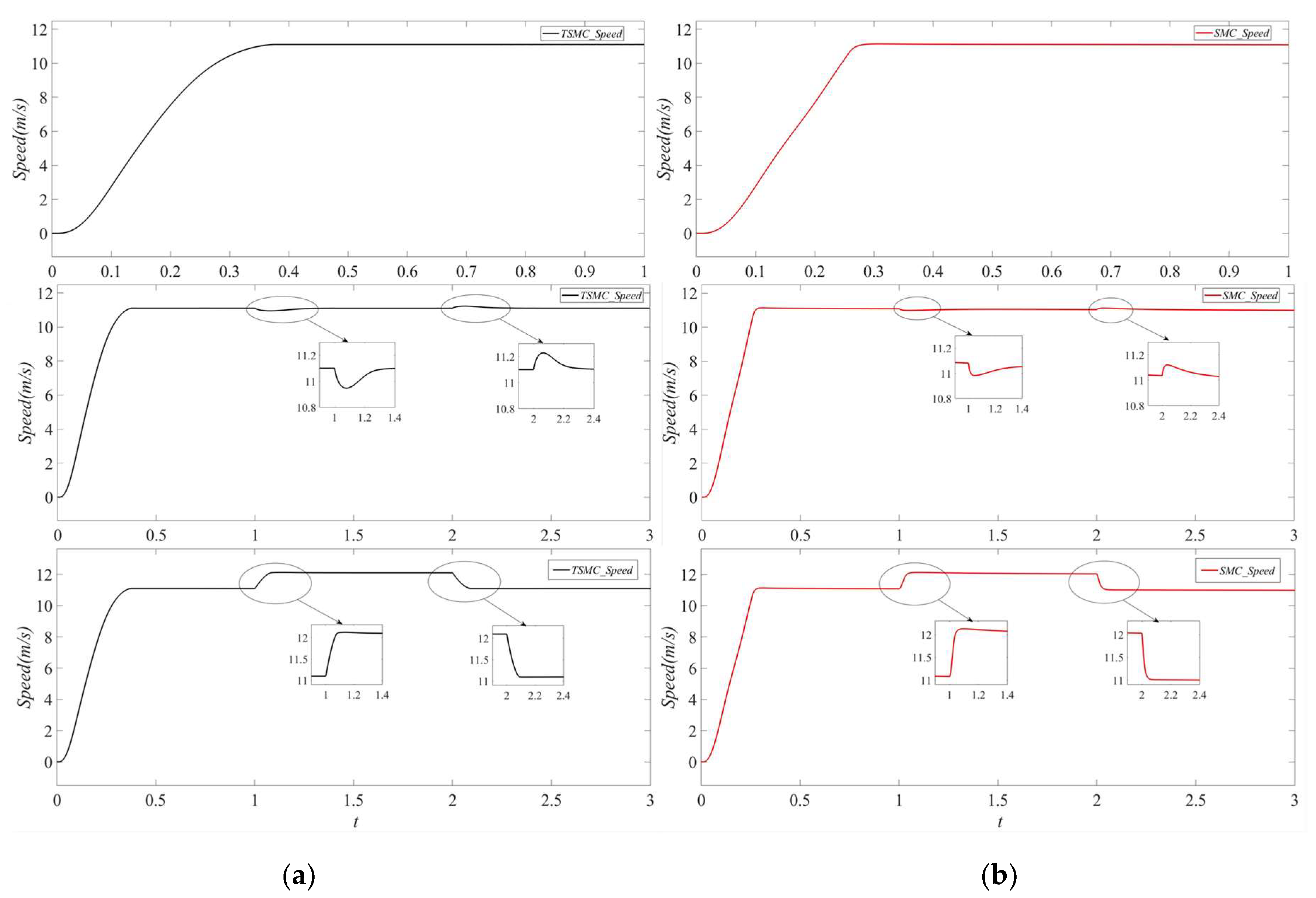
4. Simulation and Analysis

The research object of this paper is a three-phase linear induction motor, whose main parameters are shown in Table A2 of Appendix A. The PI parameter values were tuned by a combination of empirical and formulaic methods, with speed PI parameter values of 50, 450, straight-axis current PI parameter values of 0.05, 150, and cross-axis current PI parameter values of 0.1, 520. Figure 2 and Figure 3 show the structural flowchart and the block diagram of the simulation system for the sliding-mode control of the linear induction motor, respectively. In addition, the values of the c, ε and k parameters associated with the sliding-mode speed controllers in this paper are 0.2, 0.01, and 4500, respectively.
The response waveforms of the system’s three-phase current, thrust, and speed under PI and SMC at startup, with a load of 600 N and a speed of 11.1 m/s, are displayed in Figure 4. As can be seen in Table 1, the system startup response speed is slightly faster under both the traditional PI control and the action of the SMC. The response waveforms of the speed, thrust, and three-phase current show that there is overshooting in the startup of the system under the PI control, whereas the system can reach the given speed faster without overshooting. When using the SMC action, the system starts up a little quicker than when using traditional PI control.
The velocity, thrust, and single-phase current response waveforms under PI and SMC are displayed in Figure 5 when the system is accelerated and decelerated. The rated speed is abruptly increased by the system to 12.1 m/s at 1 s and then decreased to 11.1 m/s at 2 s. The response waveforms for thrust, speed, and single-phase current show that SMC and PI both perform better at regulating speed. Table 1 shows that the system’s response to SMC action in acceleration and deceleration conditions is marginally quicker than the system’s response to traditional PI control.
The response waveforms for thrust, speed, and single-phase current under PI and SMC when the system is loaded or unloaded are displayed in Figure 6. In one second, the system loads to 5000 N, and in two seconds, it drops to 600 N. Speed, thrust, and single-phase current response waveforms demonstrate that SMC and PI have comparable anti-disturbance capabilities. Table 2 illustrates that, in contrast with the traditional PI control, the system’s speed fluctuation when a load is added or subtracted is somewhat less under the influence of SMC, and the system’s resistance to load disturbance is robust.
This method results in poor dynamic and static performance on linear induction motors with large variations in motor parameters because of the complexity and fundamental invariance of the traditional vector control PI parameter tuning, as well as the drawbacks of significant overshoot and inadequate disturbance resistance. Because of this, the sliding-mode variable structure is used in this paper to enhance the motor’s dynamic and static performance as well as its anti-disturbance performance. Table 1 and Table 2 make this evident, showing that the linear induction motor performs better under the SMC than it does under traditional vector control, with a shorter acceleration and deceleration response time and a smaller speed drop when adding or removing loads, both of which are consistent with the theoretical findings.
Figure 7 illustrates the advantages of the controller designed in this paper over the traditional sliding-mode controller, which chooses the sliding-mode surface as x1 and the equal-velocity convergence law. These advantages include suppressing perturbation, accelerating response speed, and suppressing overshooting.
In summary, the sliding-mode controller proposed in this paper performs better at reducing overshooting, increasing response speed, and being robust against changes in load.

5. Conclusions

The results of the simulation demonstrate that the sliding-mode controller based on the exponential reaching law suggested in this paper is workable and efficient when applied to the vector-controlled linear induction motor speed control system. This can enhance the system’s anti-disturbance and dynamic performance. The benefits of using the SMC system over the traditional PI control include its quicker response time, reduced overshooting of speed, and increased resilience to load disturbances. This approach increases the system’s resistance to disturbances while also making it more robust. It enhances the ability of linear induction motors to handle a variety of challenging operating situations, which substantially encourages their implementation in the emergency prone fields of urban rail transportation, electromagnetic emission, and electric doors.

Author Contributions

This research article contains the authors’ contributions to the writing and completion of such an academic achievement project. The authors S.M. and J.Z. mainly completed the physical model design, data analysis, and writing of the article. The authors Y.X., H.W., X.Y. mainly performed the literature retrieval, literature summary, and literature analysis. All authors have read and agreed to the published version of the manuscript.

Funding

This research received the funding from the University’s independent project (2022504040).

Data Availability Statement

The datasets used and analyzed during the current study are available from the corresponding author on reasonable request.

Acknowledgments

Throughout the writing of this dissertation, I received a great deal of support and assistance. I want to thank my supervisor, Jinggong Zhao, whose expertise was invaluable in formulating the research questions and methodology. Your insightful feedback pushed me to sharpen my thinking and brought my work to a higher level.

Conflicts of Interest

All authors disclosed no relevant relationships.

Appendix A

Table A1. The main parameters and abbreviations of this paper are defined.
SymbolsDefinition
RsPrimary (stator) resistance
RrSecondary (rotor) resistance
RcIron loss resistance
L1sPrimary (stator) leakage inductance
L1rSecondary (rotor) leakage inductance
LsPrimary (stator) Inductance
LrSecondary (rotor) inductance
LmMagnetizing inductance
ids,  iqsPrimary d- and q-axis currents
ΨdrSecondary d-axis flux
ωsPrimary angular frequency
ωrElectric angular velocity of secondary
sSlip
ωs1Slip angular frequencies
FThrust
TElectromagnetic torque
τPole pitch
LIMLinear induction motors
SMCSliding-mode control
PIDProportion integration differentiation
RIMRotary inductance motors
SVPWMSpace vector pulse width modulation
where Ψ, L, and R represent the flux, inductance, and resistance, respectively, and the subscripts d and q indicate the components of each physical quantity in the d and q axis system, s and r refer to the secondary and primary components, and m and c are the magnetization and iron loss components. ωs and ωs1 are the primary electrical angular frequency and the slip angular frequency.
The simulation parameters are shown in Table A2.
Table A2. LIM main parameters.
ParametersValuesUnit
Pole-pair number6-
Pole pitch0.2808m
Rated flux6Wb
Primary resistance0.138Ω
Secondary resistance46.4Ω
Iron loss resistance167Ω
Magnetizing inductance0.026477H
Primary leakage inductance0.006688H
Secondary leakage inductance0.002091H
Secondary length2.476m
The Clarke transformation matrix Tα-β, and the Park transformation matrix Td-q are as follows:
T d- q = cos θ sin θ 0 sin θ cos θ 0 0 0 I 4
where I4 is a fourth-order unit matrix.
T α - β = 3 3 1 1 2 1 2 3 2 3 2 0 0 3 2 3 2 1 2 1 2 1 1 1 2 1 2 3 2 3 2 0 0 3 2 3 2 1 2 1 2 1 1 1 1 0 0 0 0 0 0 1 1 1
The coefficients Ke and Kr are as follows:
K e = 1 1 + K m K r = K 1 + K 2
where Km, K1, K2 are as follows:
K m = 1 Q 1 + S 2 e S 1 T r Q S 1 e S 2 T r Q 2 λ T r = L m + L r R r , T v = D V Q = D R r V ( L m + L lr ) λ = R r 2 L lr 2 R r L lr T r S 1 , 2 = R r 2 L lr ± λ
K 1 = R r 2 4 λ 2 L lr 2 T v e 2 S 1 T v 1 2 S 1 + e 2 S 2 T v 1 2 S 2 2 e ( S 1 + S 2 ) T v + 2 S 1 + S 2 K 2 = R r 2 4 λ 2 L lr 2 Q 1 2 e 2 S 1 T v + e 2 S 2 T v e ( S 1 + S 2 ) T v

References

  1. Li, J.Q.; Li, W.L.; Deng, G.Q.; Ming, Z. Continuous-Behavior and Discrete-Time Combined Control for Linear Induction Motor-Based Urban Rail Transit. IEEE Trans. Magn. 2016, 52, 8500104. [Google Scholar] [CrossRef]
  2. Boldea, I.; Pucci, M.; Xu, W. Design and Control for Linear Machines, Drives, and MAGLEVs—Part I. IEEE Trans. Ind. Electron. 2018, 65, 7423–7426. [Google Scholar] [CrossRef]
  3. Boldea, I.; Tutelea, L.N.; Xu, W.; Pucci, M. Linear Electric Machines, Drives, and MAGLEVs: An Overview. IEEE Trans. Ind. Electron. 2018, 65, 7504–7515. [Google Scholar] [CrossRef]
  4. Lai, C.K.; Shyu, K.K. A Novel Motor Drive Design for Incremental Motion System via Sliding-Mode Control Method. IEEE Trans. Ind. Electron. 2005, 52, 499–507. [Google Scholar] [CrossRef]
  5. Sun, Q.; Cheng, M.; Zhou, O. Variable-parameter PI control of a new biconvex permanent magnet motor speed control system. Chin. J. Electr. Eng. 2003, 7, 117–122. [Google Scholar]
  6. Oh, W.S.; Kim, Y.T.; Kim, C.S.; Kwon, T.S.; Kim, H.J. Speed control of induction motor using genetic algorithm based fuzzy controller. In Proceedings of the IECON’99. Conference Proceedings, 25th Annual Conference of the IEEE Industrial Electronics Society (Cat. No.99CH37029), San Jose, CA, USA, 29 November 1999–3 December 1999; IEEE: New York, NY, USA, 1999; Volume 2, pp. 625–629. [Google Scholar]
  7. Zhang, Z.; Wang, G.; Wang, Z.; Liu, Q.; Wang, K. Neural network based Q-MRAS method for speed estimation of linear induction motor. Measurement 2022, 205, 112203. [Google Scholar] [CrossRef]
  8. Utkin, V. Variable structure systems with sliding modes. IEEE Trans. Autom. Control 1977, 22, 212–222. [Google Scholar] [CrossRef]
  9. Hung, J.Y.; Gao, W.; Hung, J.C. Variable structure control: A survey. IEEE Trans. Ind. Electron. 1993, 40, 2–22. [Google Scholar] [CrossRef]
  10. Zhang, X.; Chen, Z.X.; Pan, J.M.; Wang, J. Fixed boundary layer sliding mode control of permanent magnet linear synchronous motors. Chin. J. Electr. Eng. 2006, 26, 115–121. [Google Scholar]
  11. Yanfeng, T.; Qingding, G. Sliding mode-H robust tracking control of permanent magnet linear synchronous motor. J. Electrotechnol. 2004, 2, 1060–1064. [Google Scholar]
  12. Chiang, H.H.; Hsu, K.C.; Li, I.H. Optimized Adaptive Motion Control Through an SoPC Implementation for Linear Induction Motor Drives. IEEE ASME Trans. Mechatron. 2015, 20, 348–360. [Google Scholar] [CrossRef]
  13. Levant, A. Chattering Analysis. IEEE Trans. Autom. Control 2010, 55, 1380–1389. [Google Scholar] [CrossRef]
  14. Utkin, V.I.; Poznyak, A.S. Adaptive sliding mode control with application to super-twist algorithm: Equivalent control method. Automatica 2013, 49, 39–47. [Google Scholar] [CrossRef]
  15. Wang, Y.; Feng, Y.; Zhang, X.; Liang, J. A New Reaching Law for Antidisturbance Sliding-Mode Control of PMSM Speed Regulation System. IEEE Trans. Power Electron. 2020, 35, 4117–4126. [Google Scholar] [CrossRef]
  16. Junejo, A.K.; Xu, W.; Mu, C.; Ismail, M.M.; Liu, Y. Adaptive Speed Control of PMSM Drive System Based a New Sliding-Mode Reaching Law. IEEE Trans. Power Electron. 2020, 35, 12110–12121. [Google Scholar] [CrossRef]
  17. Feng, L.; Sun, X.; Guo, D.; Yao, M.; Diao, K. Advanced Torque Sharing Function Strategy with Sliding Mode Control for Switched Reluctance Motors. IEEE Trans. Transp. Electrif. 2023, 10, 2302–2311. [Google Scholar] [CrossRef]
  18. Su, X.; Liu, X.; Song, Y.D. Event-Triggered Sliding-Mode Control for Multi-Area Power Systems. IEEE Trans. Ind. Electron. 2017, 64, 6732–6741. [Google Scholar] [CrossRef]
  19. Kun, D. Active power factor correction using sliding mode control with reaching law. In Proceedings of the 2007 2nd IEEE Conference on Industrial Electronics and Applications, Harbin, China, 23–25 May 2007; IEEE: New York, NY, USA, 2007. [Google Scholar]
  20. Hou, Q.; Ding, S.; Yu, X. Composite Super-Twisting Sliding Mode Control Design for PMSM Speed Regulation Problem Based on a Novel Disturbance Observer. IEEE Trans. Energy Convers. 2021, 36, 2591–2599. [Google Scholar] [CrossRef]
  21. Ge, Y.; Yang, L.; Ma, X. Adaptive sliding mode control based on a combined state/disturbance observer for the disturbance rejection control of PMSM. Electr. Eng. 2020, 102, 1863–1879. [Google Scholar] [CrossRef]
  22. Zhang, T.; Xu, Z.; Li, J.; Zhang, H.; Gerada, C. A Third-Order Super-Twisting Extended State Observer for Dynamic Performance Enhancement of Sensorless IPMSM Drives. IEEE Trans. Ind. Electron. 2020, 67, 5948–5958. [Google Scholar] [CrossRef]
  23. Qian, R.; Luo, M.; Sun, P. Improved nonlinear sliding mode control based on load disturbance observer for permanent magnet synchronous motor servo system. Adv. Mech. Eng. 2016, 8, 168781401664267. [Google Scholar] [CrossRef]
  24. Lim, S.; Nam, K. Loss-minimising control scheme for induction motors. IEE Proc. Electr. Power Appl. 2004, 151, 385. [Google Scholar] [CrossRef]
  25. Zhao, Y.; Lipo, T.A. Modeling and control of a multi-phase induction machine with structural unbalance. IEEE Trans. Energy Convers. 1996, 11, 570–577. [Google Scholar] [CrossRef]
  26. Zhao, Y.; Lipo, T.A. Space vector PWM control of dual three-phase induction machine using vector space decomposition. IEEE Trans. Ind. Appl. 1995, 31, 1100–1109. [Google Scholar] [CrossRef]
  27. Garcia, G.O.; Luis, J.C.M.; Stephan, R.M.; Watanabe, E.H. An efficient controller for an adjustable speed induction motor drive. IEEE Trans. Ind. Electron. 1994, 41, 533–539. [Google Scholar] [CrossRef]
Figure 1. Asymmetric equivalent circuit of the d–q axis system of the LIM.
Electronics 13 02352 g001
Figure 2. The structural flowchart for the sliding-mode control of the linear induction motor.
Electronics 13 02352 g002
Figure 3. The block diagram of the simulation system for the sliding-mode control of the linear induction motor.
Electronics 13 02352 g003
Figure 4. Waveforms of speed, thrust, and three-phase current response during system startup.
Electronics 13 02352 g004
Figure 5. Velocity, thrust, and single-phase current response waveforms during system acceleration and deceleration: (a) PI; (b) SMC.
Electronics 13 02352 g005
Figure 6. Waveforms of speed, thrust, and single-phase current response when the system is loaded or unloaded: (a) PI; (b) SMC.
Electronics 13 02352 g006
Figure 7. Comparison of speed simulation waveforms of TSMC and SMC: (a) TSMC; (b) SMC.
Electronics 13 02352 g007
Table 1. Speed response times of the two control strategies under different operating conditions.
ts(s)
Constant SpeedAccelerationDecelerationAdding LoadsSubtracting Loads
PI0.2591.04552.03751.31952.3846
SMC0.2581.03662.03131.30112.3376
Table 2. Speed fluctuation of the two control strategies under different operating conditions.
ts(s)
Adding LoadsSubtracting Loads
PI0.10010.0837
SMC0.0990.0829
Disclaimer/Publisher’s Note: The statements, opinions and data contained in all publications are solely those of the individual author(s) and contributor(s) and not of MDPI and/or the editor(s). MDPI and/or the editor(s) disclaim responsibility for any injury to people or property resulting from any ideas, methods, instructions or products referred to in the content.

