Article

An 18–40 GHz Ridge Waveguide Magic-T Using Stepped Conducting T-Junction Transition

1
Science and Technology on Electronic Information Control Laboratory, Chengdu 610036, China
2
School of Electronic Science and Engineering, Xiamen University, Xiamen 361005, China
3
Shenzhen Research Institute of Xiamen University, Shenzhen 518057, China
*
Author to whom correspondence should be addressed.
Electronics 2024, 13(12), 2407; https://doi.org/10.3390/electronics13122407
Submission received: 26 May 2024 / Revised: 13 June 2024 / Accepted: 19 June 2024 / Published: 20 June 2024
(This article belongs to the Section Microwave and Wireless Communications)

Abstract

:
This paper presents a wideband ridge waveguide Magic-T based on an E- and an H-arm waveguide power divider using a stepped conducting T-junction transition. The Magic-T is designed to cover the full band of 18–40 GHz with a relative bandwidth of 76%. This bandwidth cannot be achieved by a Magic-T based on a conventional rectangular waveguide. Thus, the ridge waveguide ports have been employed and an 18–40 GHz ridge waveguide Magic-T has been fabricated and measured. It is demonstrated that the proposed Magic-T achieves better than 0.3 dB insertion loss and 15 dB return loss, less than 0.2 dB magnitude imbalance, and 2.5° phase imbalance. In addition, the measured data show good agreement with the simulation results, and high isolation is also obtained.

1. Introduction

Magic-T is a four-port component that allows the input signal from sum port 1 to be divided into two output signals of equal amplitude and phase, and two output signals with equal amplitude and relative phase are obtained when the input signal is from difference port 2. As a key four-port microwave component, Magic-T is mainly used in phased array antennas, related receivers, and monopulse tracking systems; it is usually used for measurement of the direction of the incident signal. Waveguide Magic-T has obvious advantages of approximating ideal magnitude and phase properties and high power-handling capability. However, traditional waveguide Magic-Ts are usually made up of a metal E- and H-arm with a metal cone loading for impedance matching. However, most of these Magic-Ts demonstrate a narrow bandwidth of around 10% [1]. By applying different matching components such as wedge, post, pin, and iris [2,3,4], wider bandwidth can be achieved. For example, in [4], the operation bandwidth was about 30%, which benefits from adding the matching cone to five steps. There are some kinds of improved structures that have also been demonstrated. For example, in [5], a waveguide Magic-T using ridge waveguide transition and an E-plane power divider operated in the frequency range of 28–36 GHz. It is worth noting that planar structures can be used in Magic-Ts to increase the operation bandwidth. Magic-Ts based on a planar microstrip and multilayer low-temperature co-fired ceramic (LTCC) can realize more than 40% bandwidth [6,7]. LTCC technology can be used for the realization of miniaturized multilayer hybrid integrated circuits and devices for microwave and millimeter wave applications [8]. Moreover, a hybrid Magic-T using waveguide to microstrip dual-probe transition was proposed for the entire Ka-band applications [9]. Due to their characteristics of small size and easy integration, planar structures are usually used in receiving systems. However, compared to the pure waveguide configurations, these Magic-Ts with planar structures usually have large insertion losses and reduced limited power-handling capability, limiting their applications in high-power systems. For example, a less than 0.8 dB insertion loss was obtained with the LTCC Magic-T in [7], while a less than 0.5 dB insertion loss can be achieved in waveguide Magic-Ts. The power-handling capacity of waveguide Magic-Ts is usually more than several hundred watts, which is dozens of times that of planar Magic-Ts. Owing to the advantages of a lower insertion loss, higher power-handling capacity, and greater heat dissipation, waveguide Magic-Ts are suitable for high-power transmitting systems where size is not a major concern. In addition, by combining ridge and E-plane gap waveguides, a Ka-band coplanar Magic-T operating in 26–40 GHz was proposed in [10], but it occupies a further dimension corresponding to the groove gap structure. It remains a challenge to realize a high-performance Magic-T with power-handling capability and more than 42% of bandwidth, especially over a one-octave bandwidth.
To overcome the above drawbacks, we demonstrate a wide ridge waveguide Magic-T fabricated by a WRD180C24 double-ridge waveguide, which can cover the entire band of 18–40 GHz (relative bandwidth of 76%) and possesses high power-handling capability. The bandwidth of this design is wider than most of the reported Magic-Ts based on pure rectangular waveguides and planar or hybrid structures found in the literature. The Magic-T design procedure is detailed and a prototype is fabricated and measured. It is found that the proposed Magic-T achieves good performance across the full band of 18–40 GHz with small magnitude and phase imbalance, and low insertion loss characteristics.

2. Ridge Waveguide Magic-T Design

The ridge waveguide Magic-T consists of two parts, an E-plane power divider and an H-plane power divider. In the first step, the E-plane and H-plane waveguide power dividers are designed, simulated, and optimized individually by the commercial 3D high frequency simulation software (HFSS), and the initial dimensions of both divides at the match point are obtained. Then, a combined structure of a ridge waveguide Magic-T is designed, simulated, and optimized. In the fabrication, the proposed Magic-T is first divided into three independent parts for machining and then assembled through pin positioning. The entire process requires high precision in machining and assembly, which may become a challenge for extra-high-frequency waveguide devices. Waveguide components are usually made up of copper and aluminum. In this work, we choose aluminum for the design since the processing technology of aluminum is compatible with silver plating, gold plating, and conductive oxidation processes, showing lower manufacturability and manufacturing costs than copper. It should be pointed out that, with the advancement of modern machining technology, 3D printing technology can be used for integrated machining and manufacturing, which can effectively solve machining and assembly accuracy problems, reduce implementation difficulties, and also provide an alternative way to achieve more complex designs. The application of 3D printing technology has also been demonstrated in microwave components, such as filters, couplers, and waveguide slot array antennas [11,12].

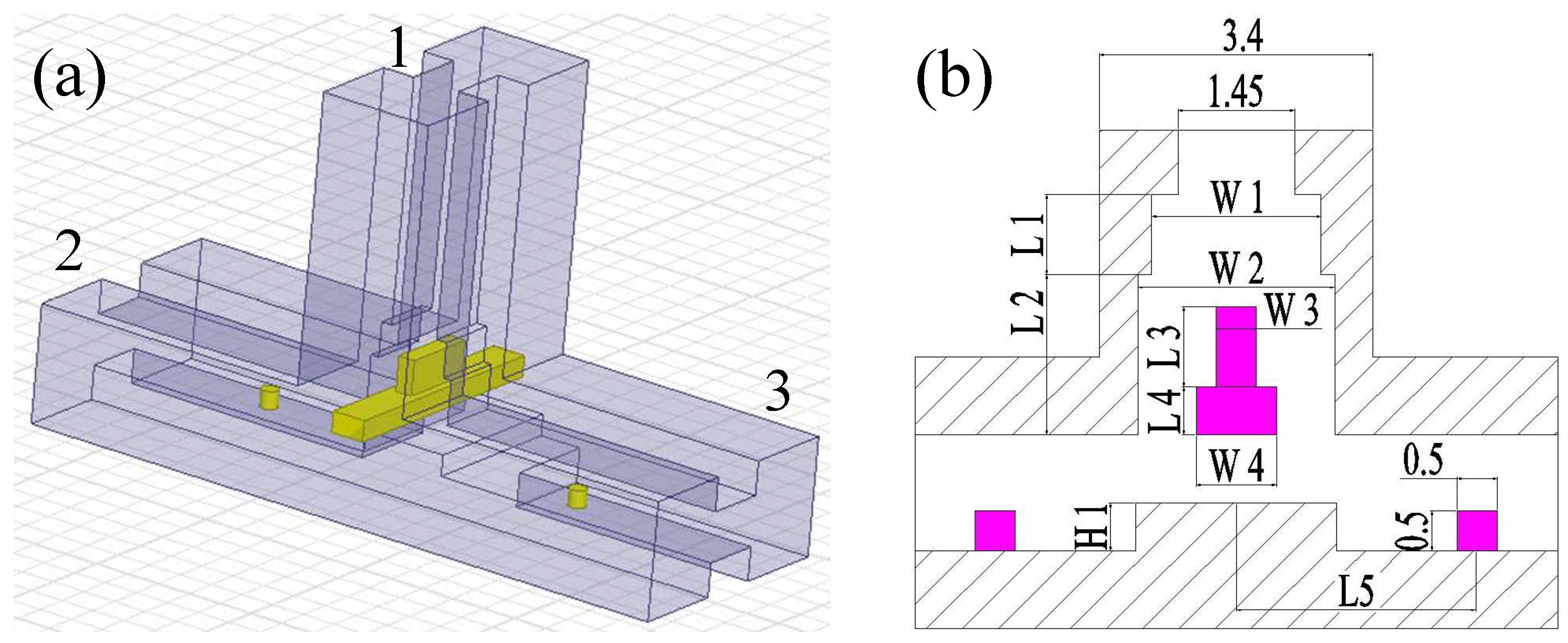
2.1. E-Plane Power Divider

Figure 1a sketches the structure of the E-plane power divider based on ridge waveguide structures. Port 1 is the “difference port”, which is divided into two waveguide branches, and the output ports 2 and 3 are symmetrical configurations. A stepped conducing T-junction transition with the height of H1 is employed between two output ports to achieve good impedance matching. There are two stepped metal impedance matching branches are placed in an E-arm that can separate the incident signal into two export transmission paths, and the detail dimension is illustrated in Figure 1b. To fabricate the two steps’ matching parts and optimized return loss of difference ports, the distance between two ridges with the initial value of 1.45 mm extends to the size of W2 by two steps. For instance, two metal cylinders with a diameter of 0.5 mm and a length of 0.5 mm are deposited on output ports which extend the operation bandwidth, and the location of the cylinders is symmetrical to each other with a distance of 5 mm to the center of the T-junction. The simulation results of this divider obtained from the commercial HFSS R17 are shown in Figure 2. It is found that both the S21 and S31 are above −3.2 dB and the S11 of port 1 is basically below −15 dB in the whole band of 18–40 GHz.

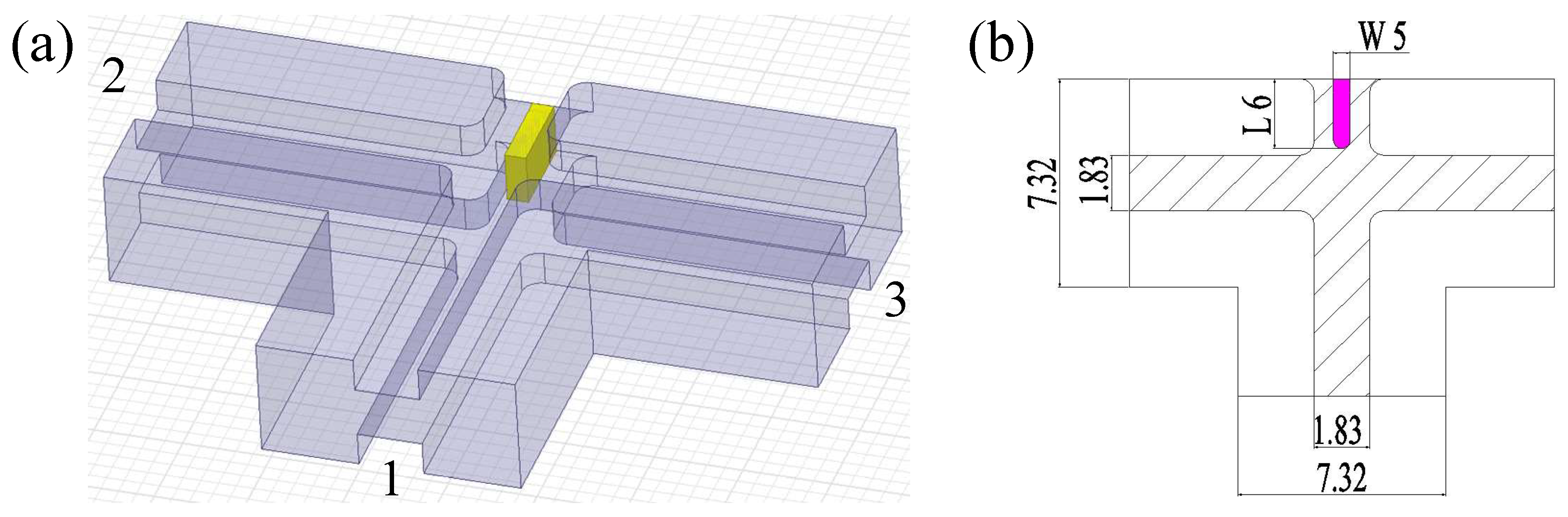
2.2. H-Plane Power Divider

The configuration of the H-plane power divider is shown in Figure 3a. Port 1 is the “sum port”, and ports 2 and 3 are the outputs. There is a conductive wall with a thickness of 0.6 mm and length of 2.45 mm placed in the center of the H-plane waveguide as shown in Figure 3b. It is worth noting that the height of the ridge waveguide close to the conductive wall was compressed from “b” size 3.4 mm to 1.45 mm, which is equal to the distance between the double ridges. Thus, this wall is connected from the lower plate to the upper plate. The length of the inductive wall was adjusted to 2.45 mm (L5) to achieve a broad bandwidth response. The simulated results of this H-Plane power divider are illustrated in Figure 4. It is found that the divider possesses good performance with both the S21 and S31 higher than −3.1 dB and the S11 is below −20 dB in the whole band of 18–40 GHz.
Based on the above dimension parameters of E-plane and H-plane power dividers, the initially combined ridge waveguide Magic-T structure is designed and sketched in Figure 5. As most of the parameters of the Magic-T are calculated in the previous design, the final dimension parameters of the Magic-T can be obtained after a small amount of optimization, as shown in Table 1. Specifically, there are some minor adjustments in the final design. For example, the corner cut is included to compensate for the discontinuity of the tee junction of the H-arm. A three-step impedance transformer is employed to match the height of “H1” as illustrated in Figure 1b, and the height of each step is 0.2 mm. In this way, ultra-wideband matching in the whole frequency range of 18–40 GHz can be achieved. As depicted in Figure 5, here, we re-assign port 1 as the sum port, port 2 as the difference port, and port 3 and port 4 are output ports. The simulation results show that all four ports are well matched and high isolation between the sum port and the difference port is also achieved.
The electric field distribution and power-handling capacity of the proposed waveguide Magic-T at 35 GHz are illustrated in Figure 6. The TE10 modes are supported in each port of the Magic-T, and the maximum electric fields are located in the T-junction transition region. The maximum electric field is about 5.4 × 10⁵ V/m when the input power is 500 W from port 1, as shown in Figure 6a, and the maximum electric field is about 5.6 × 10⁵ V/m when the input power is 500 W from port 2, as shown in Figure 6b. If we maintain the vacuum state in the structure, the simulated maximum electric field is much smaller than the breakdown threshold of the vacuum (3 × 10⁶ V/m). Thus, the power-handling capacity of the proposed waveguide Magic-T is more than 500 W, which meets most of the millimeter wave high-power applications. Figure 6c,d also illustrate the vector E-fields when the excitation signal was from the sum port 1 and difference port 2, respectively.

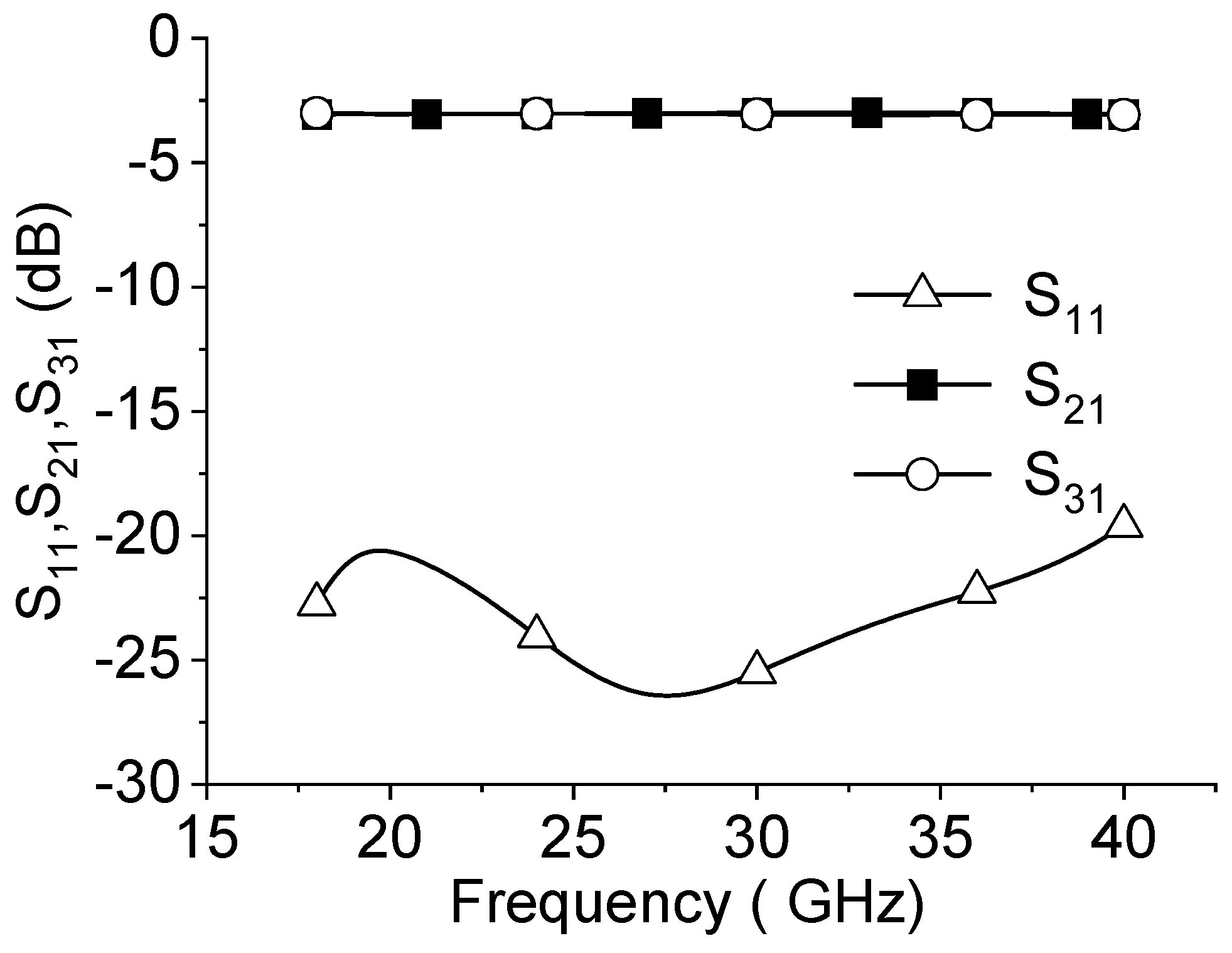
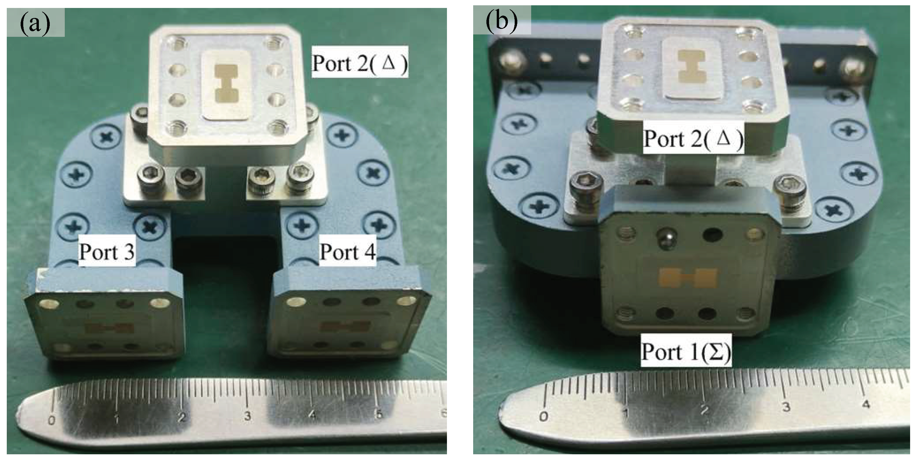
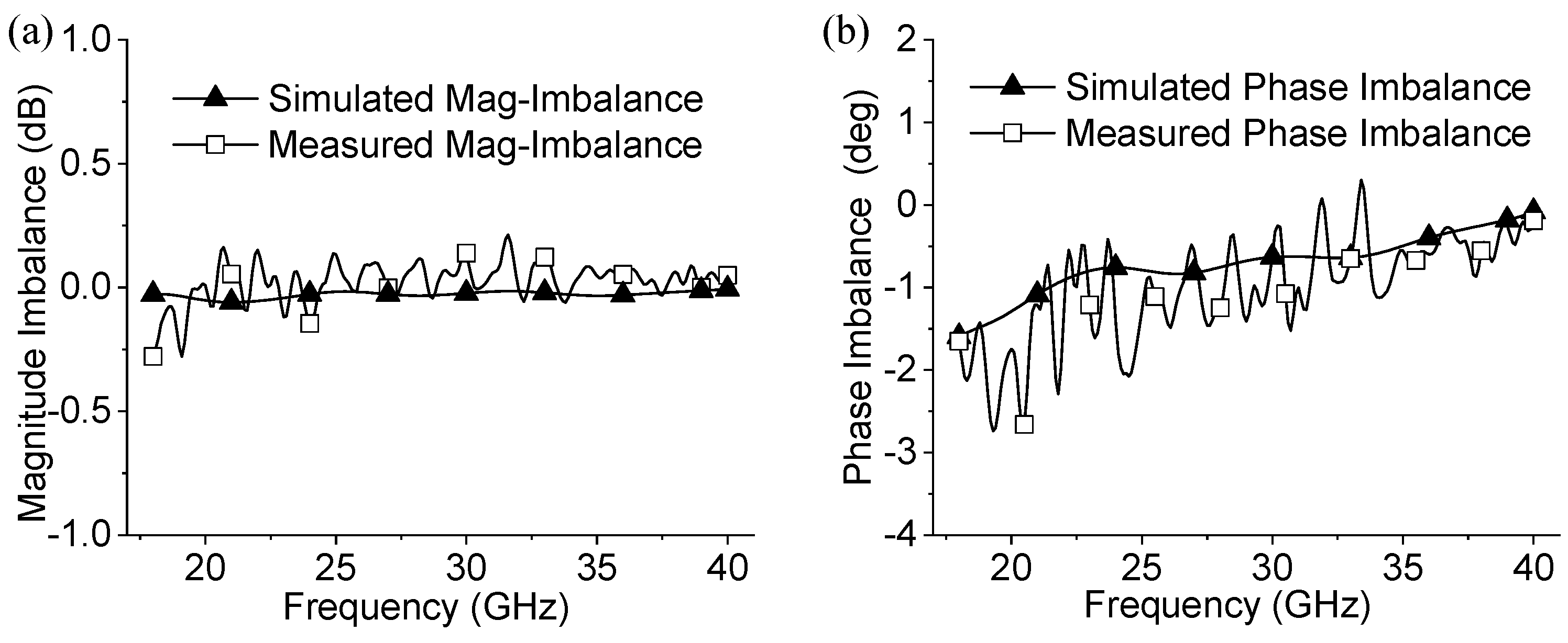
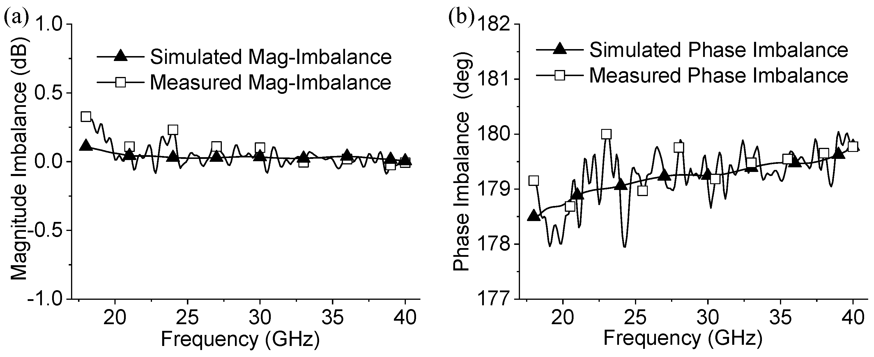
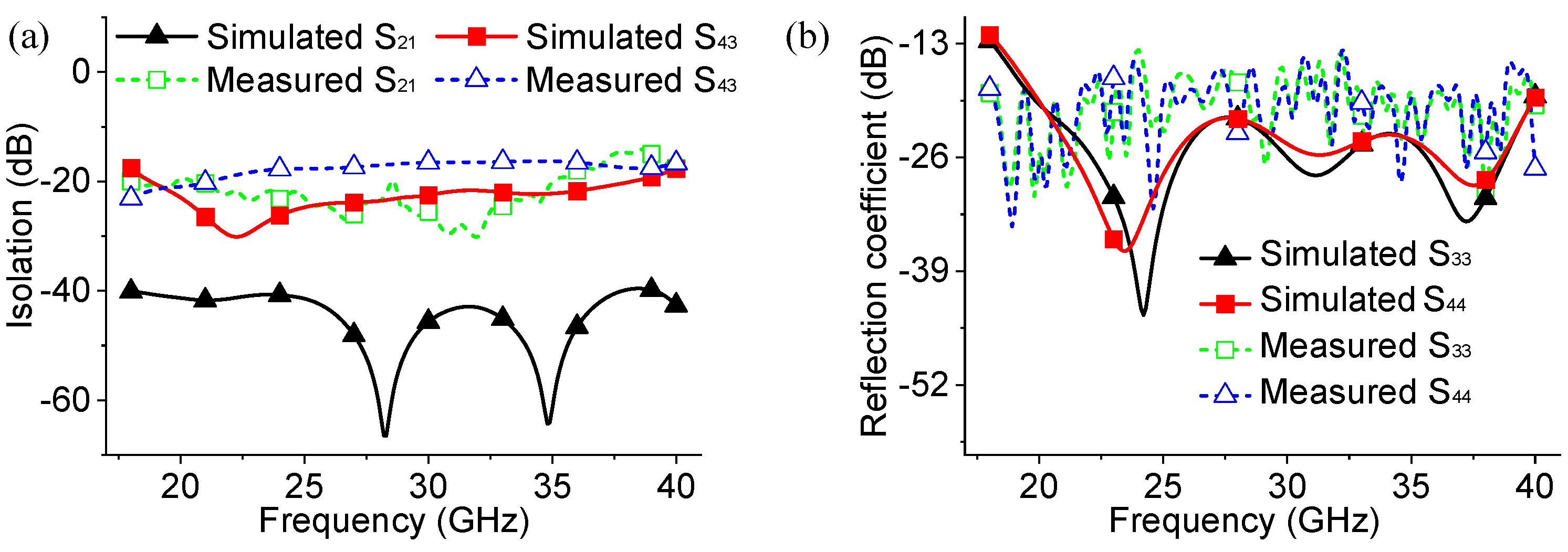
3. Measurement and Analysis

A prototype of the proposed ridge waveguide Magic-T was fabricated and measured, as shown in Figure 7. The two output ports are extended with two 90° bends to facilitate the connection for engineering applications. It should be noted that these bends are not mandatory and they can be flexibly designed according to specific requirements.
Figure 8 shows the measured results of scatting parameters in the frequency band ranging from 18 to 40 GHz. The S11 is lower than −15 dB, and the S31, S41, S32, and S42 are higher than −3.7 dB in the entire frequency band. That is to say, the insertion losses of the sum port and difference port are better than −0.7 dB, including the insertion loss of two connectors with 0.4 dB loss which transform the WRD180C24 ridge waveguide port to the coaxial ports connected to the vector network analyzer.
The simulation and experimental results are compared in Figure 9, Figure 10 and Figure 11. It is found that both results are in good agreement. The maximum magnitude and phase imbalance are less than 0.2 dB and 2.5° in 18–40 GHz, showing good magnitude and phase imbalance performance. The isolation between the sum port and the difference ports is more than 16 dB in 18–35 GHz and more than 15 dB in 35–40 GHz, respectively.
The performance comparison of the proposed ridge waveguide Magic-T and some designs from the previous literature is summarized in Table 2. For example, the K-band planar Magic-T based on LTCC technology [7] shows an insertion loss of 0.8 dB, a return loss of 8 dB, a magnitude imbalance of 0.8 dB, and a phase imbalance of 2.5° in 17–25 GHz (relative bandwidth of 38%). Similarly, a Ka-band hybrid Magic-T [9] demonstrated an insertion loss of 0.7 dB, a return loss of 15 dB, a magnitude imbalance of 0.25 dB, and a phase imbalance of 3° in 26–40 GHz (relative bandwidth of 42%). In contrast, the proposed ridge waveguide Magic-T not only offers a significantly wider bandwidth of 18–40 GHz (relative bandwidth of 76%) but also exhibits superior performance metrics: an insertion loss of 0.3 dB, a magnitude imbalance of 0.2 dB, and a phase imbalance of 2.5°. Additionally, the ridge waveguide Magic-T has the advantage of higher power-handling capability over those with planar structures. However, the conventional machining process used for its fabrication can introduce challenges related to machining and assembly accuracy at extremely high frequencies. Three-dimensional printing technology provides a potential solution to these challenges by enabling the fabrication of complex structures with virtually any shape, thereby increasing design flexibility.

4. Conclusions

A broadband ridge waveguide Magic-T with the features of low loss, high power-handling capability, good isolation, and excellent magnitude and phase imbalance performance has been analyzed, fabricated, and measured. The measured results show that the proposed Magic-T has superior characteristics in bandwidth which cover the entire K and Ka-bands in the frequency band of 18–40 GHz. The proposed Magic-T may have promising applications in wideband microwave, millimeter wave circuits and systems, such as antenna feed networks and power amplifier systems.

Author Contributions

L.Y. conceived the research; W.P., C.L. and H.W. undertook the simulations, experiments, and analysis. All authors have read and agreed to the published version of the manuscript.

Funding

This research is supported in part by the National Natural Science Foundation of China (U2230118), Natural Science Foundation of Xiamen Municipality (3502Z20227169), Guangdong Basic and Applied Basic Research Foundation (2024A1515011479), and Shenzhen Science and Technology Program (JCYJ20210324121606017).

Institutional Review Board Statement

Not applicable.

Informed Consent Statement

Not applicable.

Data Availability Statement

The details of data taken are cited in the text.

Conflicts of Interest

The authors declare no conflicts of interest.

References

  1. Chu, Q.; Wu, Q.; Mo, D. A Ka-Band E-Plane Waveguide Magic-T With Coplanar Arms. IEEE Trans. Microw. Theory Tech. 2014, 62, 2673–2679. [Google Scholar] [CrossRef]
  2. Beyer, R.; Rosenberg, U. CAD of magic tee with interior stepped post for high performance designs. IEEE MTT-S Int. Microw. Symp. Dig. 2003, 2, 1207–1210. [Google Scholar]
  3. Leal-Sevillano, C.A.; Ruiz-Cruz, J.A.; Montejo-Garai, J.R.; Relollar, J.M. Compact broadband couplers based on the waveguide Magic-T junction. In Proceedings of the 43rd European Microwave Conference, Nuremberg, Germany, 6–10 October 2013; pp. 151–154. [Google Scholar]
  4. Hwang, K.C. Design and Optimization of a Broadband Waveguide Magic-T Using a Stepped Conducting Cone. IEEE Microw. Wireless Compon. Lett. 2009, 19, 539–541. [Google Scholar] [CrossRef]
  5. He, Y.; Mo, D.; Wu, Q.; Chu, Q. A Ka-Band Waveguide Magic-T With Coplanar Arms Using Ridge Waveguide Transition. IEEE Microw. Wireless Compon. Lett. 2017, 27, 965–967. [Google Scholar] [CrossRef]
  6. U-Yen, K.; Wollack, E.J.; Papapolymerou, J.; Laskar, J. A broadband planar Magic-T using microstrip-slotline transitions. IEEE Trans. Microw. Theory Tech. 2008, 56, 172–177. [Google Scholar] [CrossRef]
  7. Peng, W.; Xiao, Q.; Chen, X. K-Band Planar Magic-T Using LTCC Technology. IEEE Microw. Wireless Compon. Lett. 2017, 27, 715–718. [Google Scholar] [CrossRef]
  8. Shafique, M.F.; Robertson, I.D. Fabrication of Microstructures in LTCC Technology Using Selective Laser Ablation. IEEE Trans. Compon. Packag. Manuf. Technol. 2015, 5, 845–851. [Google Scholar] [CrossRef]
  9. Peng, S.; Pu, Y.; Wu, Z.; Luo, Y. Compact Ka-band magic-T using waveguide to microstrip dual-probe transition. IEEE Microw. Wireless Compon. Lett. 2022, 32, 946–949. [Google Scholar] [CrossRef]
  10. Farahbakhsh, A. Ka-Band Coplanar Magic-T Based on Gap Waveguide Technology. IEEE Microw. Wireless Compon. Lett. 2020, 30, 853–856. [Google Scholar] [CrossRef]
  11. Zhang, Y.; Zhang, F.; Gao, Y.; Xu, J.; Guo, C.; Shang, X. 3D printed waveguide step-twist with bandpass filtering functionality. IEEE Electron. Lett. 2020, 50, 527–529. [Google Scholar] [CrossRef]
  12. Le Sage, G.P. 3D Printed Waveguide Slot Array Antennas. IEEE Access 2016, 4, 1258–1265. [Google Scholar] [CrossRef]
Figure 1. (a) Three-dimensional view of the E-Plane power divider. (b) Sectional view and detail dimension of E-Plane power divider (W1 = 2.1 mm, W2 = 2.6 mm, W3 = 0.5 mm, W4 = 1 mm, L1 = 1 mm, L2 = 2 mm, L3 = 1 mm, L4 = 0.6 mm, H1 = 0.6 mm, L5 = 5 mm).
Electronics 13 02407 g001
Figure 2. Simulation results of the E-plane ridge waveguide power divider.
Electronics 13 02407 g002
Figure 3. (a) Three-dimensional view of H-Plane power divider. (b) Sectional view and detail dimension of H-Plane power divider (W5 = 0.6 mm, L6 = 2.45 mm).
Electronics 13 02407 g003
Figure 4. Simulation results of the H-plane ridge waveguide power divider.
Electronics 13 02407 g004
Figure 5. Three-dimensional view of the proposed ridge waveguide Magic-T.
Electronics 13 02407 g005
Figure 6. (a) Electric field distribution from excitation signal of port 1 at 35 GHz. (b) Electric field distribution from excitation signal of port 2 at 35 GHz. (c) Vector_E distribution of difference port 1 input at 35 GHz. (d) Vector_E distribution of sum port 2 input at 35 GHz.
Electronics 13 02407 g006
Figure 7. (a) Front view of the fabricated ridge waveguide Magic-T prototype. (b) Back view of the fabricated Magic-T prototype.
Electronics 13 02407 g007
Figure 8. (a) Measured S31, S41, and S11 of sum port 1. (b) Measured S32, S42, and S22 of difference port 2.
Electronics 13 02407 g008
Figure 9. (a) Simulated and measured magnitude imbalance of sum port. (b) Simulated and measured phase imbalance of sum port.
Electronics 13 02407 g009
Figure 10. Simulated and measured magnitude imbalance of difference port (a) and phase imbalance of difference port (b).
Electronics 13 02407 g010
Figure 11. (a) Simulated and measured E-H S21 and co-linear isolation S21. (b) Simulated and measured reflection coefficients S33 and S44.
Electronics 13 02407 g011
Table 1. Dimension parameters for the Magic-T (unit: mm).
ParameterW1W2W3W4H1W5
Value2.12.50.5710.60.6
ParameterL1L2L3L4L5L6
Value11.281.40.652.35
Table 2. Comparison of waveguide Magic-T performance.
Refs.Freq. (GHz)BW.IL (dB)RL (dB)ΔA (dB)Δf (°)
[5]28–3625%−1150.27
[7]17–2538%0.880.86
[9]26–4042%0.7150.253
[10]26–4042%0.2515-1.3
This work18–4076%0.3150.22.5
Disclaimer/Publisher’s Note: The statements, opinions and data contained in all publications are solely those of the individual author(s) and contributor(s) and not of MDPI and/or the editor(s). MDPI and/or the editor(s) disclaim responsibility for any injury to people or property resulting from any ideas, methods, instructions or products referred to in the content.

