
Manifold Optimization-Based Data Detection Algorithm for Multiple-Input–Multiple-Output Orthogonal Frequency-Division Multiplexing Systems under Time-Varying Channels


Abstract
:1. Introduction
2. System Model
3. Conventional Data Detection Algorithm Based on Manifold Optimization
| Algorithm 1 Data detection algorithm based on manifold optimization for time-invariant channels. |
4. Proposed Manifold Optimization-Based Data Detection Algorithm for MIMO-OFDM Systems Under Time-Varying Channels
4.1. Problem Formulation and Solving
| Algorithm 2 The proposed manifold optimization-based data detection algorithm for MIMO-OFDM systems under time-varying channels. |
4.2. Improved Algorithm with Less Complexity
| Algorithm 3 The proposed less-complex algorithm. |
|
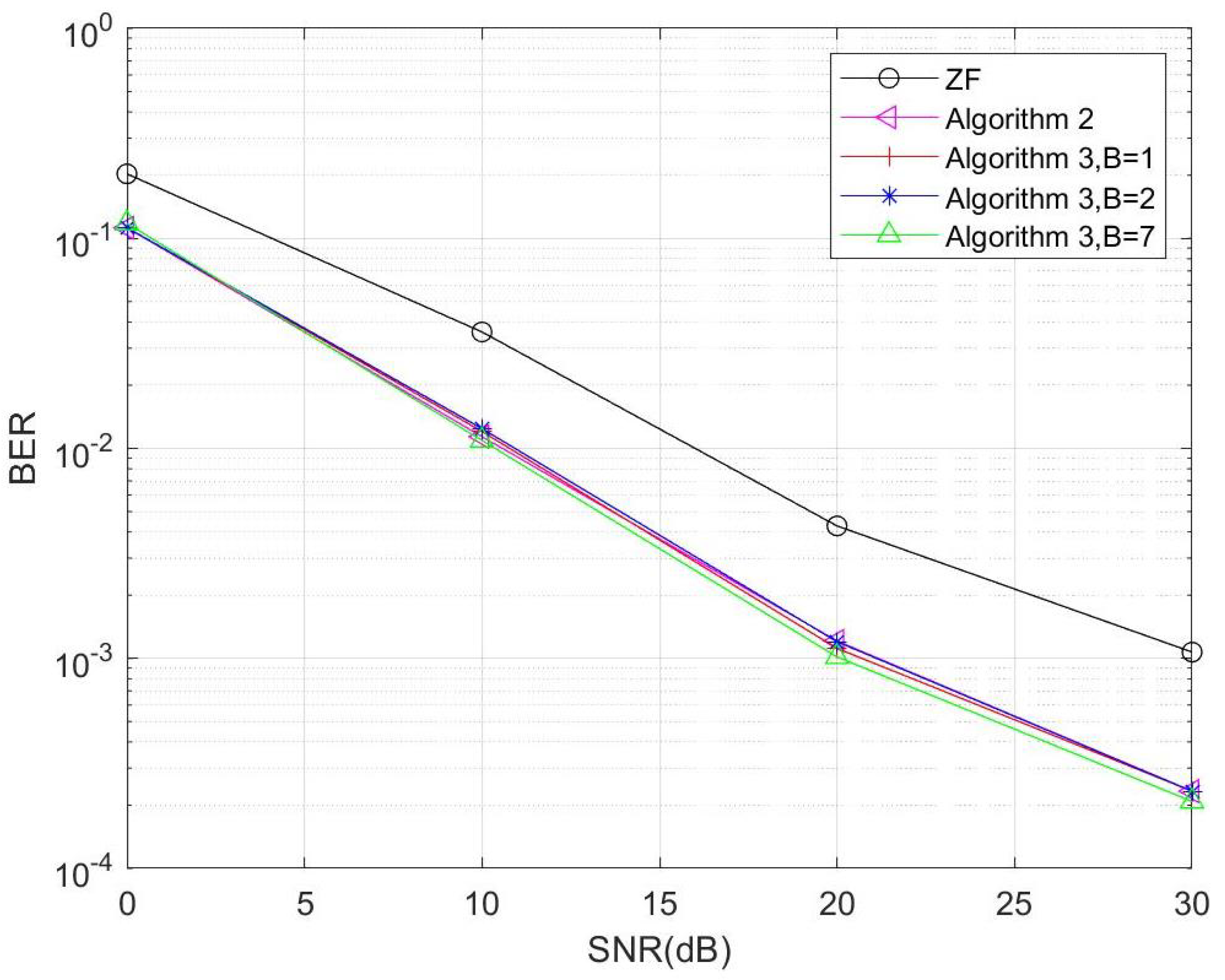
5. Simulation Results and Discussions
6. Conclusions
Author Contributions
Funding
Data Availability Statement
Conflicts of Interest
References
- Rusek, F.; Persson, D.; Lau, B.K.; Larsson, E.G.; Marzetta, T.L.; Edfors, O.; Tufvesson, F. Scaling Up MIMO: Opportunities and Challenges with Very Large Arrays. IEEE Signal Process. Mag. 2013, 30, 40–60. [Google Scholar] [CrossRef]
- Andrews, J.G.; Buzzi, S.; Choi, W.; Hanly, S.V.; Lozano, A.; Soong, A.C.K.; Zhang, J.C. What Will 5G Be? IEEE J. Sel. Areas Commun. 2014, 32, 1065–1082. [Google Scholar] [CrossRef]
- Farzamnia, A.; Moung, E.; Hlaing, N.W.; Kong, L.E.; Haldar, M.K.; Fan, L.C. Analysis of MIMO System through Zero Forcing and Minimum Mean Square Error Detection Scheme. In Proceedings of the 2018 9th IEEE Control and System Graduate Research Colloquium (ICSGRC), Shah Alam, Malaysia, 3–4 August 2018; pp. 172–176. [Google Scholar] [CrossRef]
- Zhang, B.; Yu, J.L.; Lai, J.W. A fast subspace channel estimation for STBC-based MIMO-OFDM systems. In Proceedings of the 2014 11th International Symposium on Wireless Communications Systems (ISWCS), Barcelona, Spain, 26–29 August 2014; pp. 75–79. [Google Scholar] [CrossRef]
- Scherb, A.; Zheng, C.; Kuhn, V.; Kammeyer, K. Comparison of methods for iterative joint data detection and channel estimation. In Proceedings of the 2004 IEEE 59th Vehicular Technology Conference, VTC 2004-Spring (IEEE Cat. No.04CH37514). Milan, Italy, 17–19 May 2004; Volume 1, pp. 98–102. [Google Scholar] [CrossRef]
- Zhou, Y.; Ng, T.S. Performance analysis on MIMO-OFCDM systems with multi-code transmission. IEEE Trans. Wirel. Commun. 2009, 8, 4426–4433. [Google Scholar] [CrossRef]
- Zhou, Y.; Ng, T.S. MIMO-OFCDM systems with joint iterative detection and optimal power allocation. IEEE Trans. Wirel. Commun. 2008, 7, 5504–5516. [Google Scholar] [CrossRef]
- Zhong, K.; Wu, Y.C.; Li, S. Signal Detection for OFDM-Based Virtual MIMO Systems under Unknown Doubly Selective Channels, Multiple Interferences and Phase Noises. IEEE Trans. Wirel. Commun. 2013, 12, 5309–5321. [Google Scholar] [CrossRef]
- Hu, J.; Liu, X.; Wen, Z.; Yuan, Y.X. A Brief Introduction to Manifold Optimization. J. Oper. Res. Soc. China 2020, 8, 199–248. [Google Scholar] [CrossRef]
- Cao, Y.; Yin, H.; He, G.; Debbah, M. Manifold Learning-Based CSI Feedback in Massive MIMO Systems. In Proceedings of the ICC 2022—IEEE International Conference on Communications, Seoul, Republic of Korea, 16–20 May 2022; pp. 225–230. [Google Scholar] [CrossRef]
- Chen, J.C. Manifold Optimization Approach for Data Detection in Massive Multiuser MIMO Systems. IEEE Trans. Veh. Technol. 2018, 67, 3652–3657. [Google Scholar] [CrossRef]
- Hong, X.; Gao, J.; Chen, S. Semi-Blind Joint Channel Estimation and Data Detection on Sphere Manifold for MIMO with high-order QAM Signaling. J. Frankl. Inst. 2020, 357, 5680–5697. [Google Scholar] [CrossRef]
- Yu, X.; Tu, L.; Yang, Q.; Yu, M.; Xiao, Z.; Zhu, Y. Hybrid Beamforming in mmWave Massive MIMO for IoV With Dual-Functional Radar Communication. IEEE Trans. Veh. Technol. 2023, 72, 9017–9030. [Google Scholar] [CrossRef]
- Li, Z.; Wang, S.; Wen, M.; Wu, Y.C. Secure Multicast Energy-Efficiency Maximization With Massive RISs and Uncertain CSI: First-Order Algorithms and Convergence Analysis. IEEE Trans. Wirel. Commun. 2022, 21, 6818–6833. [Google Scholar] [CrossRef]
- Absil, P.A.; Mahony, R.; Sepulchre, R. Optimization Algorithms on Matrix Manifolds; Princeton University Press: Princeton, NJ, USA, 2008; Volume 78. [Google Scholar] [CrossRef]
- Boumal, N.; Mishra, B.; Absil, P.A.; Sepulchre, R. Manopt, a matlab toolbox for optimization on manifolds. J. Mach. Learn. Res. 2014, 15, 1455–1459. [Google Scholar]
- Gong, C.; Hu, D. A GAN-Based Channel Estimation Method for MIMO OFDM Systems. In Proceedings of the 2023 8th International Conference on Communication, Image and Signal Processing (CCISP), Chengdu, China, 17–19 November 2023. [Google Scholar]
- Zhang, B.; Hu, D.; Wu, J.; Xu, Y. An Effective Generative Model Based Channel Estimation Method With Reduced Overhead. IEEE Trans. Veh. Technol. 2022, 71, 8414–8423. [Google Scholar] [CrossRef]


| Computational Operations | Computational Complexity |
|---|---|
| Algorithm | Subframe Length B | Computational Complexity |
|---|---|---|
| Algorithm 2 | \ | |
| Algorithm 3 | 1 | |
| 2 | ||
| 7 |
| Simulation Parameter Table | |
|---|---|
| Transmit Antennas | 4 |
| Receive Antennas | 4 |
| Subcarriers K | 64 |
| Data Frame Length | 14 |
| Doppler Shift/Hz | 400 |
| Sampling Rate/MHz | 30.72 |
Disclaimer/Publisher’s Note: The statements, opinions and data contained in all publications are solely those of the individual author(s) and contributor(s) and not of MDPI and/or the editor(s). MDPI and/or the editor(s) disclaim responsibility for any injury to people or property resulting from any ideas, methods, instructions or products referred to in the content. |
© 2024 by the authors. Licensee MDPI, Basel, Switzerland. This article is an open access article distributed under the terms and conditions of the Creative Commons Attribution (CC BY) license (https://creativecommons.org/licenses/by/4.0/).
Share and Cite
Li, Y.; Hu, D. Manifold Optimization-Based Data Detection Algorithm for Multiple-Input–Multiple-Output Orthogonal Frequency-Division Multiplexing Systems under Time-Varying Channels. Electronics 2024, 13, 2555. https://doi.org/10.3390/electronics13132555
Li Y, Hu D. Manifold Optimization-Based Data Detection Algorithm for Multiple-Input–Multiple-Output Orthogonal Frequency-Division Multiplexing Systems under Time-Varying Channels. Electronics. 2024; 13(13):2555. https://doi.org/10.3390/electronics13132555
Chicago/Turabian StyleLi, Yumeng, and Die Hu. 2024. "Manifold Optimization-Based Data Detection Algorithm for Multiple-Input–Multiple-Output Orthogonal Frequency-Division Multiplexing Systems under Time-Varying Channels" Electronics 13, no. 13: 2555. https://doi.org/10.3390/electronics13132555
APA StyleLi, Y., & Hu, D. (2024). Manifold Optimization-Based Data Detection Algorithm for Multiple-Input–Multiple-Output Orthogonal Frequency-Division Multiplexing Systems under Time-Varying Channels. Electronics, 13(13), 2555. https://doi.org/10.3390/electronics13132555