Article

Enhancing Wireless Charging for Electric Vehicles: Active Load Impedance Matching and Its Impact on Efficiency, Cost and Size

by
Nicolas Allali
Valeo Power, 95800 Cergy, France
Electronics 2024, 13(14), 2720; https://doi.org/10.3390/electronics13142720
Submission received: 4 June 2024 / Revised: 28 June 2024 / Accepted: 4 July 2024 / Published: 11 July 2024
(This article belongs to the Topic Advanced Wireless Charging Technology)

Abstract

:
This paper presents an advanced Wireless Power Transfer (WPT) system for electric vehicles (EVs) featuring Active Load Impedance Matching (ALIM) at the rectification stage. Unlike traditional synchronous rectification, ALIM dynamically adjusts load impedance, optimizing energy transfer efficiency and reducing thermal stresses, system costs, and mass. The system incorporates two circuits optimized for distinct frequency bands: one operates below 10 kHz using standard copper wiring for cost-effectiveness, and the other at 85 kHz, which significantly reduces the mass of the onboard coil and magnetic circuit while ensuring interoperability according to SAE J2954 standard. Our approach enhances charging efficiency across various operating conditions, improves thermal management, and minimizes maintenance costs. Additionally, it enables partial compensation for vehicle misalignment and ground assembly impedance, further boosting efficiency and interoperability. Experimental results demonstrate a notable increase in efficiency and reduction in system mass, confirming the superiority of the ALIM-equipped WPT system over conventional solutions. This paper underscores the potential of ALIM to advance the scalability, efficiency, and economic viability of wireless EV charging technology, promoting broader adoption and sustainability in EV infrastructures. By providing a comprehensive solution that addresses key challenges in wireless charging, our work paves the way for more efficient and cost-effective EV charging systems.

1. Introduction

Wireless charging for electric vehicles (EVs) presents a promising development within the automotive sector, offering a seamless and user-friendly recharge solution poised to transform the user experience. This technology is particularly suited for autonomous vehicles, removing the need for manual intervention during recharging and thus facilitating EV integration into daily routines and enhancing their adoption in the market.
The integration of Renewable Energy Sources (RES) for charging EVs is pivotal in enhancing sustainable transportation. The Vehicle-to-Everything (V2X) technology, encompassing Vehicle to Grid (V2G) and Vehicle to Home (V2H), facilitates bidirectional energy flow, supporting grid stability and home energy management [1]. Incorporating RES with V2X enables EVs to act as mobile energy storage units, optimizing energy utilization from sources like solar and wind power [2]. Such integration not only reduces carbon emissions but also enhances energy security and efficiency in urban areas [3,4].
However, several obstacles impede the widespread implementation of Wireless Power Transfer (WPT) within the automotive market [5]. High system costs, significant equipment mass, and suboptimal energy efficiency pose major challenges. Moreover, the difficulty of coexisting with nearby communication systems at the standard WPT frequency of 79 to 90 kHz [6] further restricts its adoption.
At the core of these challenges is the critical need for matching the battery’s charge impedance with the charging circuit [7,8,9,10,11]. Introducing active charge impedance adaptation as an innovative solution offers a significant enhancement in charging efficiency and reverse mode (V2X mode) performance. This approach enables active compensation for vehicle misalignment or ground clearance variation, essential for maximizing energy transfer efficiency, and underscores the importance of achieving high performance in V2X mode [12,13], which operates at reduced power compared to the vehicle charging mode.
Although the adoption of 85 kHz WPT technology traditionally faces challenges such as the prohibitive cost of the Litz wire needed to minimize energy losses at higher frequencies [14], our research also explores advancements at this standard frequency, which allows interoperability with other WPT systems [6]. Our innovative approach brings benefits to the following aspects:
  • Efficiency at Low Power: Enhanced low-power performance in vehicle charging and V2X modes at both low frequencies below 10 kHz and high frequencies like 85 kHz [11,12].
  • Efficiency at Low Operational Frequencies: Achieving better efficiency at frequencies below 10 kHz, allowing the use of standard plain copper wire instead of Litz wire in WPT inductors.
  • Loss Distribution: Improved loss distribution in the system, reducing cooling system costs and facilitating integration [15].
  • Partial Compensation for Misalignment: Partially compensates for the detuning of the compensation circuit caused by vehicle misalignment, thereby reducing performance loss [16].
This paper aims to delve deeply into the potential of active charge impedance adaptation in WPT systems. We will start by discussing the concepts of charge impedance and tuned circuits, followed by active compensation for misalignment and ground clearance through the emulation of reactive components. Subsequently, we introduce the theoretical design of a low-frequency WPT charger with Active Load Impedance Matching for an 800 V system. The implementation of such a charger on a demonstration vehicle follows this. After discussing these implementations, we explore the application of the Active Load Impedance Matching (ALIM) strategy at an 85 kHz operating frequency. We have filed specific patents for all original and innovative inventions featured in this publication.

2. Compensation Circuit

In the context of our project dedicated to developing an advanced EV charging solution, we rely on a DC power supply, Vdcin, which is available to provide the necessary energy for charging. This predefined infrastructure, capable of delivering a voltage greater than 600 V, combined with high battery voltages, typically ranging from 400 V to 800 V, is crucial for supporting fast and efficient charging operations. Achieving an output power equal to or greater than 11 kW is central to meeting contemporary demands for accelerated charging, while the bidirectional capability enriches our system, allowing it to support V2X applications and ensure dynamic interaction with the electrical grid. These ambitious objectives must be achieved while minimizing production costs and simplifying system complexity to the greatest extent. Let us now compare the various standard compensation circuits shown in Figure 1 through the lens of an automotive application.
The SS (Series–Series) circuit stands out for its simplicity and low cost, offering a promising avenue for economical and large-scale production. However, it is important to be aware of its limitations, particularly its sensitivity to misalignment and moderate bidirectional capability, which could restrict its efficiency in high-power charging scenarios and V2X applications.
The SP (Series–Parallel) circuit, with its remarkable energy efficiency even in the case of slight misalignment and its ability to efficiently manage bidirectionality thanks to advanced control, presents itself as a suitable solution for V2X applications. Nonetheless, this configuration is penalized by higher production costs and complexity, which may conflict with our cost-reduction objectives.
The PS (Parallel–Series) circuit shares several advantages with the SP circuit, particularly in terms of efficiency and bidirectionality, making it capable of meeting the need for rapid and bidirectional charging. However, its moderate cost and complexity could make it less attractive from an economic optimization viewpoint.
As for the PP (Parallel–Parallel) circuit, it excels in terms of misalignment tolerance and energy efficiency, positioning it as the ideal choice for high-power charging applications and demanding V2X scenarios. Its superiority in bidirectionality management is also notable. However, the highest production cost and significant complexity of this configuration make it less desirable from a cost minimization and system simplification perspective.
Given these considerations, the SS (Series–Series) circuit emerges as the most appropriate solution for an automotive application [5,17,18]. Although it faces challenges in terms of misalignment sensitivity and bidirectional functionality, an innovative approach to system management and control will be presented next to significantly improve its performance. This strategy fully leverages the available DC voltage, optimizing the efficiency and capabilities of the charging system without unnecessarily increasing the cost or complexity of the equipment.

3. Operation Frequency

The operating frequency (Fsw) plays a pivotal role in the design of high-power WPT chargers, significantly affecting key parameters such as size, weight, energy efficiency, cost, and health and safety considerations due to electromagnetic field emissions. While the majority of WPT system manufacturers for vehicles choose an operating frequency range between 79 kHz and 90 kHz [6], which necessitates the use of Litz wires for primary and secondary coils to minimize losses [19], this approach contributes to the high production cost of these systems. Our analysis not only suggests that lowering the operating frequency to a sufficiently low range could allow the use of standard copper wires, thereby reducing costs, but also considers operations at 85 kHz. Operating at 85 kHz helps ensure interoperability [20] with other wireless chargers on the market and can reduce the mass of the equipment involved. This dual-frequency approach allows for broader application possibilities and enhances the accessibility of WPT technology while addressing the challenges of cost and equipment efficiency.

4. Load Impedance Matching

4.1. Introduction

The efficiency of energy transfer in WPT chargers for EVs hinges on precise impedance matching between the battery-side rectification stage and the resonant circuit optimal load impedance depicted in Equation (3). This matching ensures that the maximum energy generated by the charger is effectively captured and stored by the battery, thereby minimizing energy losses. Fine-tuning these impedances enhances the charging speed, increases the overall system efficiency [9,10,11,21], and maintains operational stability, which is crucial for meeting the high standards of performance demanded in the automotive industry.
This chapter introduces a frequency-equivalent electrical model for a WPT charger with an SS compensation circuit. We will explain how to set the equivalent load impedance for synchronous active rectification and conclude with a new control strategy for the active rectifier in WPT applications, focusing on improving performance by dynamically adjusting load impedance.

4.2. Load Impedance Matching with Synchronous Rectification

In resonant converters like those used in WPT systems, we can simplify the analysis of an electrical circuit by using the First Harmonic Approximation (FHA) [22,23]. This approach helps to make the math easier by assuming the signals in the circuit are sinusoidal, which works best when the circuit’s operating frequency is very close to its resonant frequency.
The standard control strategy for the selected circuit shown in Figure 2 is as follows. Duty cycles α1 and α2 are set to 50%, with a phase shift φ of α2 relative to α1 utilized to modulate the voltage on the primary side of the circuit. On the secondary side, control signals α3 and α4 engage synchronous rectification using transistors Q5 to Q8, effectively mimicking the operation of a diode Graëtz Bridge based on the direction of the current Is.
The following definitions apply:
φ ∈ (0–π) radian: Phase shift delay of Q4/Q3 leg with Q1/Q2 as reference leg;
αX ∈ (0–1): Duty cycle of the respective X leg;
k ∈ (0–1): Magnetic coupling coefficient between Lp and Ls coils.
It is now appropriate to linearize the transistor stages, namely, the inverter Q1–Q4 and the rectifier Q5–Q8, using the FHA method. The fundamental harmonic of the voltage Vin can be expressed by the first-order term of its Fourier series decomposition. Equation (1) expresses the RMS amplitude of the voltage at the working frequency.
V a c i n φ = 2 2 π × V d c i n × s i n φ 2
R a c L = 8 π 2 × V b a t t 2 P
where P [W] is the delivered power to the load.
As demonstrated by Dr. R. L. Steigerwald [24,25], a full-bridge synchronous rectification circuit subjected to a sinusoidal current exhibits, in our case, an equivalent impedance, as expressed in Equation (2). This formulation elucidates that the load impedance enforced by synchronous rectification significantly hinges on the rectification voltage Vbatt dictated by the battery and the power conveyed to it. It is imperative to understand that, with synchronous rectification, the resonant circuit will be coupled to a load impedance that is highly contingent upon the operating conditions of the converter.
From the equivalent linearized quantities RacL and Vacin, and by establishing an equivalence of the primary components reflected to the secondary circuit based on the turns ratio of the inductances Lp and Ls, we propose in Figure 3 a non-isolated and frequency-based linear equivalent diagram of the WPT charger structure presented in Figure 2.
The following definitions apply:
Vacin_s = Vacin × L s L p : Vacin input voltage seen by secondary side circuit;
Rp: Sum of primary ESRs seen by secondary side circuit;
ZCp = 1 j ω C p × L p L s : Cp impedance seen by secondary side circuit;
ZLp = 1 k × L s × j ω : Uncoupled Lp inductor impedance seen by secondary side circuit;
Zm = k × L s × j ω : Coupled or mutual Ls inductor impedance;
ZLs = 1 k × L s × j ω : Uncoupled Ls inductor impedance;
ZCs = 1 j ω C s : Cs impedance;
Rs: Sum of secondary side ESRs.
Assuming that the capacitors Cp and Cs are sized such that L p × C p = L s × C s , and that the angular frequency ω matches the system’s resonant value 1 L p × C p , a simplified expression of the optimal-efficiency load impedance of the considered WPT charger can be provided, as shown in Equation (3) [11].
Zload_opt = R s × 1 + ω × k 2 × L p × L s R p × R s
Firstly, Equation (2) illustrates that the battery voltage significantly affects RacL, which represents the load impedance imposed by classical synchronous rectification, and the power delivered to it. On the other hand, Equation (3) outlines the optimal load impedance of the WPT circuit, a value solely determined by the system’s passive parameters, including passive electronic components, the vehicle’s position relative to the transmission inductance, and the coupling coefficient k. Given the variability in operational power, battery voltage, vehicle positioning relative to the transmission inductance, and temporal drift of components such as capacitors, it becomes evident that achieving an impedance match between the optimal WPT charging circuit and the load impedance dictated by synchronous rectification, applicable across all operating scenarios, is unfeasible. Note that, unfortunately, other passive compensation circuits with synchronous rectification would provoke the same observation to a greater or lesser extent.
To maximize the performance of such a system, the usual approach is to size all components for nominal operating conditions [26]. The system then exhibits appealing performance for a nominal battery voltage, nominal vehicle positioning, and maximum G2V charging mode power. The temporal modulation of transmitted power, the switch from G2V to V2X operation modes, vehicle alignment and ground clearance, and the battery voltage presented are all parameters that degrade the performance of this system.

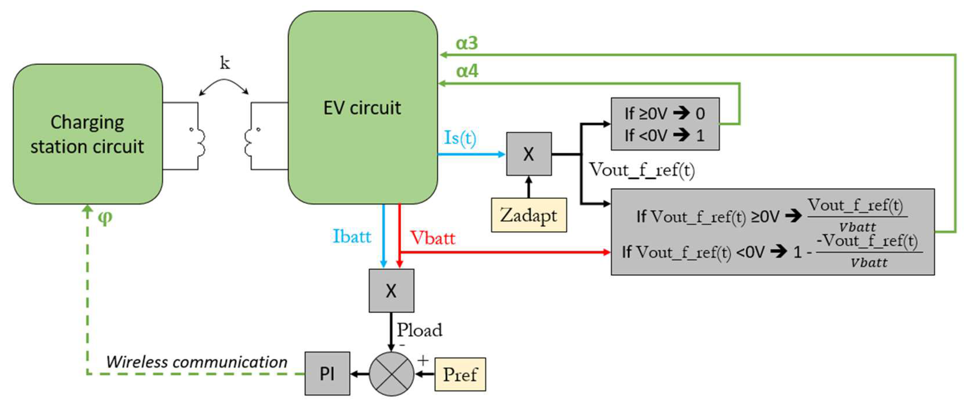
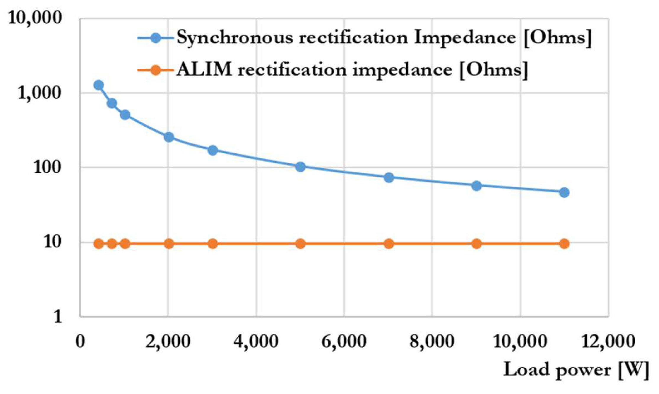
4.3. Rectification with Active Load Impedance Matching (ALIM) Strategy

The optimal impedance Zload_opt at the vehicle side of the WPT charging circuit integrates several parameters related to vehicle placement and the compensated resonant circuit. They are imposed parameters over which we have no control. However, the load impedance RacL presented by the secondary rectification circuit is the result of the control strategy of this stage. We suggest controlling the rectification stage in such a way that it exhibits an equivalent impedance beneficial for our system’s operation, with Zload_opt as the target value. Within a theoretical framework where the load impedance is maintained as constant through a control process implemented by us, which does not incur any power loss, the efficiency of the WPT charger would remain constant. This observation remains valid regardless of the battery voltage and the level of power being transferred.
To accomplish this objective, we suggest employing a transistor control strategy for the rectification stage, similar to the well-established Totem-Pole AC/DC Boost PFC converter approach [27]. In our specific case, this means utilizing Ohm’s law to enforce a voltage Vacout at the rectification stage’s input terminals, adhering to Equation (4).
V a c o u t ( t ) = I s ( t ) × Z a d a p t
V i n d ( t ) = k × L s × d I p d t
As defined in Equation (5) and depicted in Figure 4, the secondary resonant circuit is powered by the induced voltage Vind(t). This circuit is loaded with the voltage Vacout, the value of which can be dynamically adjusted in real time following Equation (4) using the described method below.
Referencing the schematic in Figure 5, we identify two switching legs, each characterized by its own duty cycle and switching frequency. If Zadapt has only a real part component, the Q7/Q8 leg is controlled based on the current direction, utilizing synchronous rectification control. This leg is termed the polarity branch as it adjusts the Vout voltage to align with the measured Is current direction and phase shift. During charging, the duty cycle of this leg theoretically equals 50%, disregarding dead-time intervals.
The second leg, Q5/Q6, referred to as the fast leg, operates at a switching frequency we call Fadapt, which is significantly higher than the primary side inverter, with a duty cycle defined by Equation (6). The purpose of this duty cycle is to sustain a constant and optimal load impedance Zadapt in the receiving circuit to enhance energy efficiency or increase transferred power, depending on the requirement.
α 3 t = V a c o u t ( t ) V b a t t = I s t + V o u t D e l a y × Z a d a p t V b a t t       w h e n     Vout_f ( t ) 0 V
α 3 t = 1 V a c o u t ( t ) V b a t t = 1 I s t + V o u t D e l a y × Z a d a p t V b a t t   w h e n       Vout_f ( t ) < 0 V
Z a d a p t = R a d a p t + j × B a d a p t
V o u t D e l a y = a r c t a n ( B a d a p t R a d a p t ) × 1 2 π × F s w
Z a d a p t × I s m a x V b a t t
0 Ω < Z a d a p t 4 × R a c L π
The duty cycle α3 defined in Equation (6) indicates a specific limitation inherent to the chosen full-bridge rectification circuit for this application, delineating its operational range as 0 ≤ α3 ≤ 1. Equation (9) articulates this electrical constraint, highlighting that the maximum output voltage Vacout achievable by the reception system cannot surpass the battery voltage Vbatt during charging. Further, as Equation (10) elucidates, the magnitude of the impedance Zadapt cannot exceed the natural impedance of synchronous rectification by a factor of 4 π . This boundary does not impact the design of a reversible WPT charger for automotive applications with a battery voltage above 200 V. For lower-voltage applications or those with different optimization requirements, we have also patented a suite of power-reversible electronic circuits enabling broader modulation of the equivalent impedance Zadapt of the rectifier/inverter stage.
Figure 6 elucidates the secondary circuit’s electrical parameters, offering a clearer understanding of its operation. It reveals Vout(t)’s frequency spectrum, which splits into two key sections: the base harmonic at the Fsw frequency observable in Vout_f(t), and another segment reflecting the switched Vbatt voltage, akin to a PWM signal at the Fadapt frequency. For optimal system performance, including stable operation, precise Zadapt impedance emulation, and minimized high-frequency ripple in Is(t), it is crucial to select an Fadapt markedly higher than the Fsw. Series capacitive compensation, because it selects specific frequencies in both primary and secondary circuits, greatly lowers the ripple in the Fadapt frequency of Is(t), and is very important for EMI filtering.
In this example, it can be observed that the signal Vout_f(t) is precisely in phase with Is(t), indicating that the emulated impedance at the secondary side is purely resistive. The paragraph V.4 will discuss the advantages of incorporating an imaginary component into Zadapt.
Modulating the Vout(t) signal with a carrier frequency Fadapt, while keeping the duty cycle synchronized with a switching frequency Fsw, requires the use of transistors capable of high-frequency switching. This requirement also limits the maximum frequency that Fsw can achieve. In the context of WPT chargers operating at high frequencies, such as 85 kHz, an alternative circuit for power-reversible rectifier/inverter circuits with active load impedance adjustments is presented in Section 7.

4.4. Control Law

Implementing control in a WPT circuit with an ALIM strategy is practically straightforward and incurs a negligible additional cost compared to a synchronous rectification circuit. The process initiates with a two-phase iterative initialization. The first phase involves conducting a frequency sweep around the operating frequency of the inverter to pinpoint the optimal Fsw value within a range confined to the bandwidth of the specific WPT charger. Subsequently, we perform a sweep of potential charge impedance values at the rectification circuit to identify the most suitable Zadapt for the circuit under operational conditions, aiming to achieve the desired power output with the highest efficiency. Given that Zadapt impacts performance and the optimal Fsw value (and vice versa), iterating through these two phases a few times is advised to ascertain the optimal Fsw/Zadapt pairing based on the circuit’s operational conditions.
After completing the parameter identification phase for Fsw and Zadapt, we propose that the system utilizes two distinct and independent control strategies, as outlined in Figure 7. The arithmetic operation detailed in Equation (6) and sign detection directly derive the configuration of signals α3 and α4, requiring minimal computational resources. The detection of the sign of the current Is(t) is also relatively simple to achieve since the waveform is sinusoidal and of low frequency.
A control loop system employing a Proportional–Integral (PI) controller manages power transfer, producing the internal phase reference φ for the inverter. The vehicle sends the control variable Phi to the charging station using a communication protocol specific to automotive WPT charging [6]. This method is the most straightforward approach, particularly suited to the demands of battery charging, where immediate responsiveness is not critical.

5. Application Case: 800 V 11 kW 7 kHz Bidirectional Wireless Charger

5.1. Product Definition

The transition to 800 V battery systems represents a significant advancement for EVs, offering faster charging times and increased efficiency. By doubling the voltage compared to traditional 400 V architectures, this technology enables rapid charging through reduced current requirements, thereby minimizing power losses and thermal dissipation. It also promotes a more optimized vehicle design through the adoption of more compact and lightweight electronic components [28]. Despite the challenges presented, such as the need to develop compatible charging infrastructures, this technological progress is promising for significantly enhancing the performance and appeal of electric vehicles. This ambition underpins our proposal to define a generic WPT charger, which aligns with this trend towards more efficient and rapid electromobility.
The specifications of the WPT charger under consideration here include:
  • Nominal battery voltage at 800 V. Full range is [300–900 V];
  • Supply DC voltage at 800 V;
  • Maximum charging power: 11 kW;
  • Maximum V2X power: 11 kW;
  • Maximum EV coil diameter: 400 mm;
  • Maximum charging station coil diameter: 450 mm;
  • Nominal coil-to-coil airgap: 100 mm.

5.2. Sizing Results

While the specific techniques used in the design of the primary and secondary inductances for this application are beyond the scope of this publication and are not elaborated upon, we do outline the general and electrical parameters of this design in Table 1.
The sizing results presented herein are derived from the comprehensive optimization process of the wireless charging system, subject to certain constraints. These constraints include the usage of standard copper wire in the coils and the dimensions and onboard mass of the coils, as well as the level of the magnetic field generated around the perimeter of the vehicle, which does not exceed the limits set by the ICNIRP standard for WPT chargers [29]. Using the parameters defined in Table 1 and Equation (3), we establish that the optimal load impedance is 21.4 Ω in EV charging mode and 27.6 Ω in V2X mode.

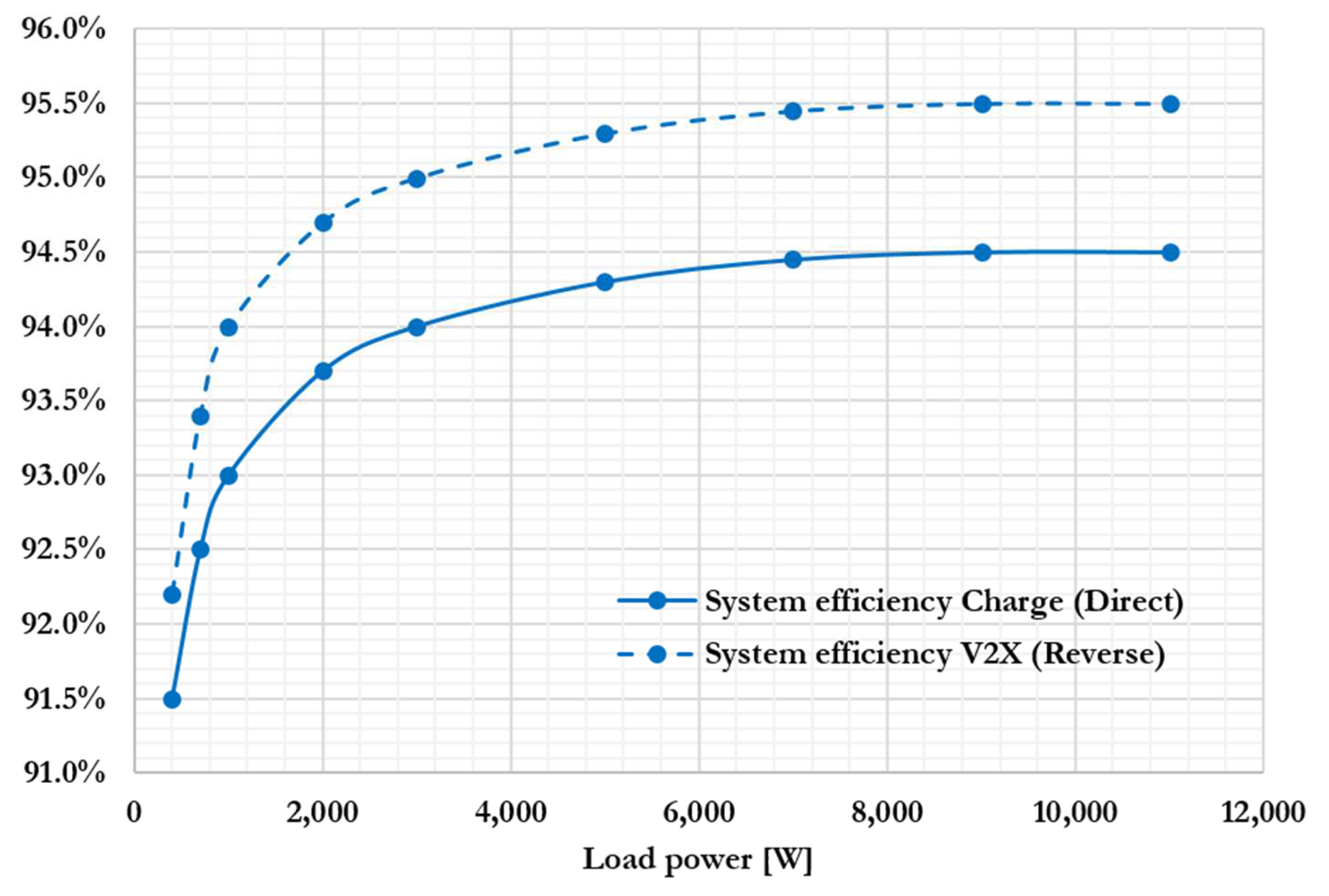
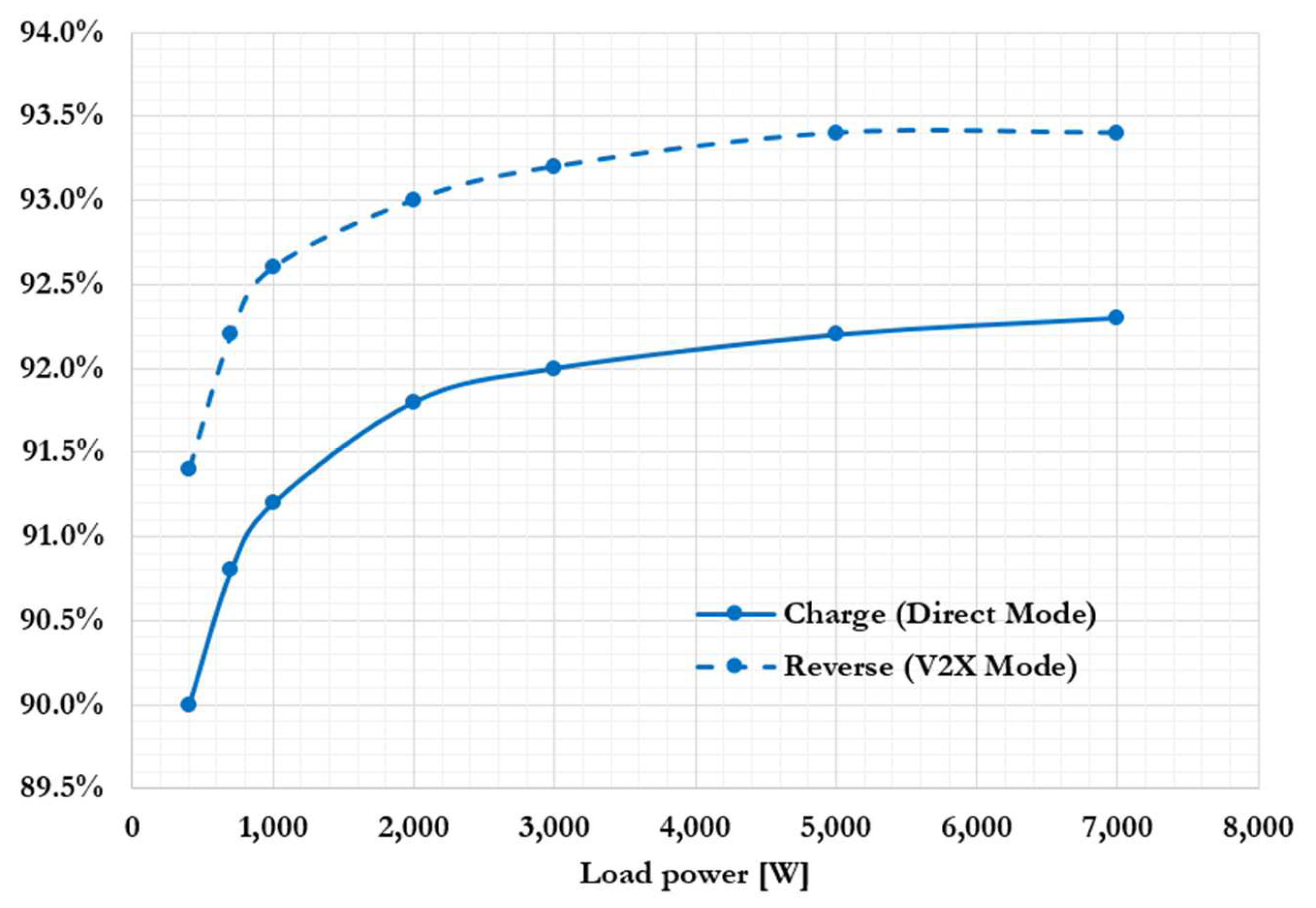
5.3. Overall Performances

An analytical model of the entire system is developed, incorporating the intrinsic parasitics of each electronic component in the power circuit, as well as losses due to system control and switching losses inherent to the ALIM rectification strategy. We correlate and validate this model against performance measurements under real-world conditions using the demonstration vehicle presented in Section 6.
Figure 8 illustrates the energy efficiency performance of the complete system under nominal conditions. As anticipated and discussed in Section 4, the efficiency remains relatively constant across the majority of the power transfer range explored.
The observation shows that the efficiency in V2X mode is, on average, 1% higher than in vehicle charging mode. This difference can be attributed to the asymmetrical coil design, which stems from differing mass and size constraints for the primary and secondary coils within the optimization algorithm.
To better understand the advantages of the ALIM rectification strategy, we present in Figure 9 a comparison of the ALIM strategy performance against conventional synchronous rectification on the same power circuit definition.
In addition to demonstrating significantly lower efficiency at full power, we also observe that the efficiency with synchronous rectification drastically decreases at lower power levels. This phenomenon can be explained by the fact that the equivalent load impedance in this mode increases substantially when the transmitted power is low, as indicated by Equation (2). In this specific case, a higher load impedance significantly deviates the system from its optimal load impedance for efficiency, leading to a substantial increase in current within the power-emitting coil, and thereby causing significant conduction losses. This current predominantly circulates in the primary’s magnetizing inductance and does not transfer any power to the load. Conversely, the ALIM rectification control strategy effectively limits the magnetizing current seen at the primary, thereby minimizing unnecessary losses.
The V2X mode is primarily intended for relatively low-power scenarios such as V2G (Vehicle-to-Grid) [12] or V2H (Vehicle-to-Home) scenarios [13]. The reduced efficiency observed at low power levels, inherent to the synchronous rectification technique, renders this mode of rectification incompatible with the high-performance expectations of the application, in contrast to the ALIM rectification strategy.

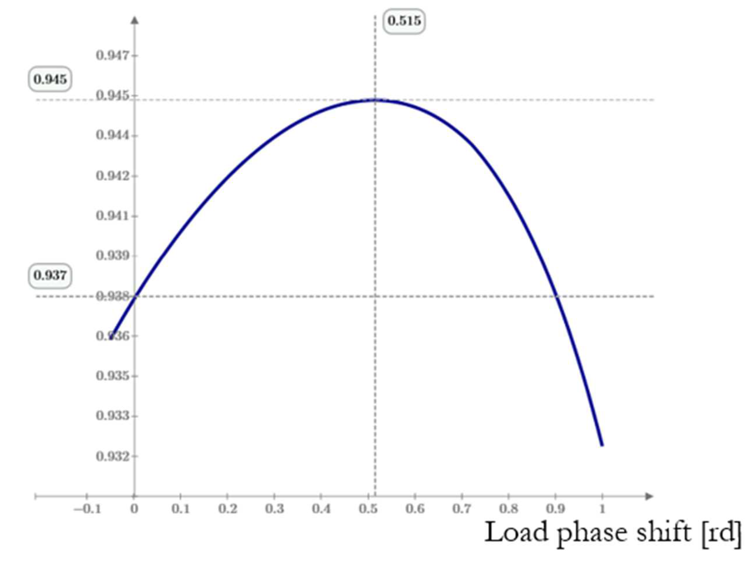
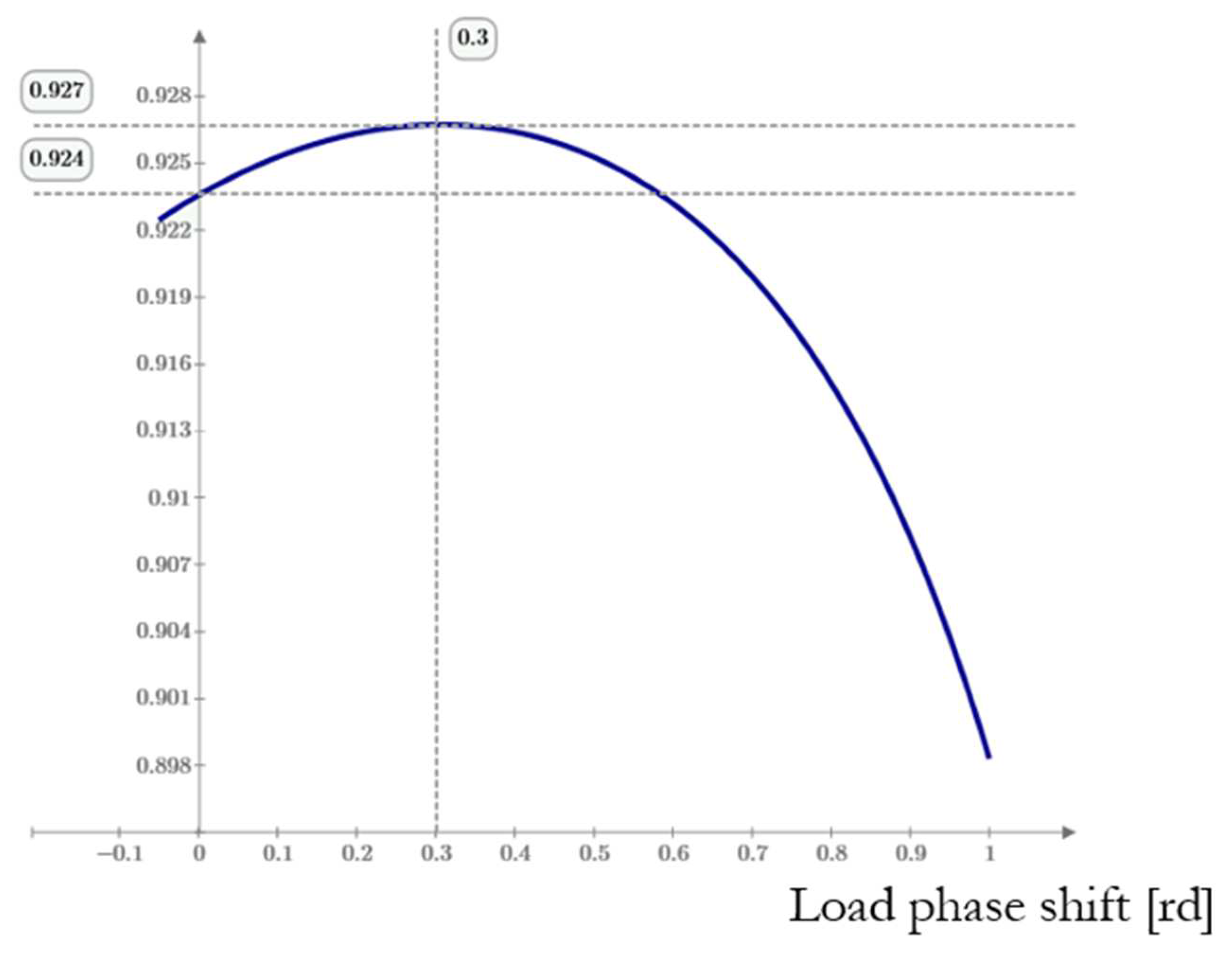
5.4. Sensitivity to Parameter Drift

Following from Section 4.3, this section highlights the expected benefits of integrating an imaginary part into the load impedance for emulation at the rectification stage. Inductive charging technology is inherently susceptible to variations in various system parameters. Temporal drift in components such as capacitors [30] or changes in the values of coils and magnetic coupling due to factors like vehicle ground clearance and the electromagnetic environment are concrete examples of parameter variation causes. These variations lead to a resonance frequency shift and a decrease in energy efficiency [31]. Operating outside the resonance frequency, without a compensation device, results in two main disadvantages: a reduced maximum theoretical power transmission and an additional decrease in efficiency. A potential solution could be to adjust the operating frequency; however, this typically means increasing it, which intensifies the parasitic frequency effect on the coils’ series equivalent resistance, thus reducing efficiency.
Although the efficiency lost due to a reduction in magnetic coupling cannot be directly recuperated, we propose to recalibrate the system’s resonance frequency to the initial operating frequency by incorporating an imaginary part into the load impedance, namely, by introducing a phase shift between the output voltage Vout_f(t) and the current Is(t).
Figure 10 serves as an initial case study, examining the impact of a 25% decrease in the Cs capacitance value. The figure illustrates that, by retaining a working frequency of 7 kHz and applying a phase shift of 0.515 radians to Vout_f(t) relative to Is(t), we can recover to an efficiency level of 94.5%, equivalent to that achieved with the system’s nominal parameters, as depicted in Figure 8.
A subsequent example, presented in Figure 11, underscores the utility of the imaginary part when the inductances Lp and Ls, along with the magnetic coupling, are decreased by 15%. This condition models a misalignment between the Lp and Ls coils, such as might be encountered if a vehicle is poorly positioned on its charging pad. The reduced magnetic coupling notably affects the maximum achievable efficiency, causing it to decline from 94.5% to 92.7%. Nevertheless, we observe that, in this example, the imaginary component has facilitated a recovery of 0.3% in efficiency, offsetting the system’s resonance frequency shift.
The two scenarios highlighted demonstrate the advantage of introducing a positive imaginary component into the equivalent load impedance. It should be observed that, depending on the specific case, comparable benefits can also be achieved with a negative imaginary part, which corresponds to a delay in the voltage Vout_f(t) with respect to the current Is(t).
Incorporating an imaginary part into the load impedance comes with certain considerations. It requires the availability of a voltage reserve on Vout_f(t) to preserve the same level of power transmission and may also, in some cases, necessitate an increase in the effective voltage applied across the primary resonant circuit via the φ parameter.
To conclude this section, it is noteworthy that the rectification system with the ALIM strategy ensures a preservation of high efficiency, which remains virtually constant across varying battery voltages, on the condition that the emulated load impedance does not change, specifically avoiding rectifier saturation. In the context of the 800 V system discussed, we expect efficiencies ranging from 94.36% to 94.52% as the battery voltage fluctuates from 300 V to 900 V.

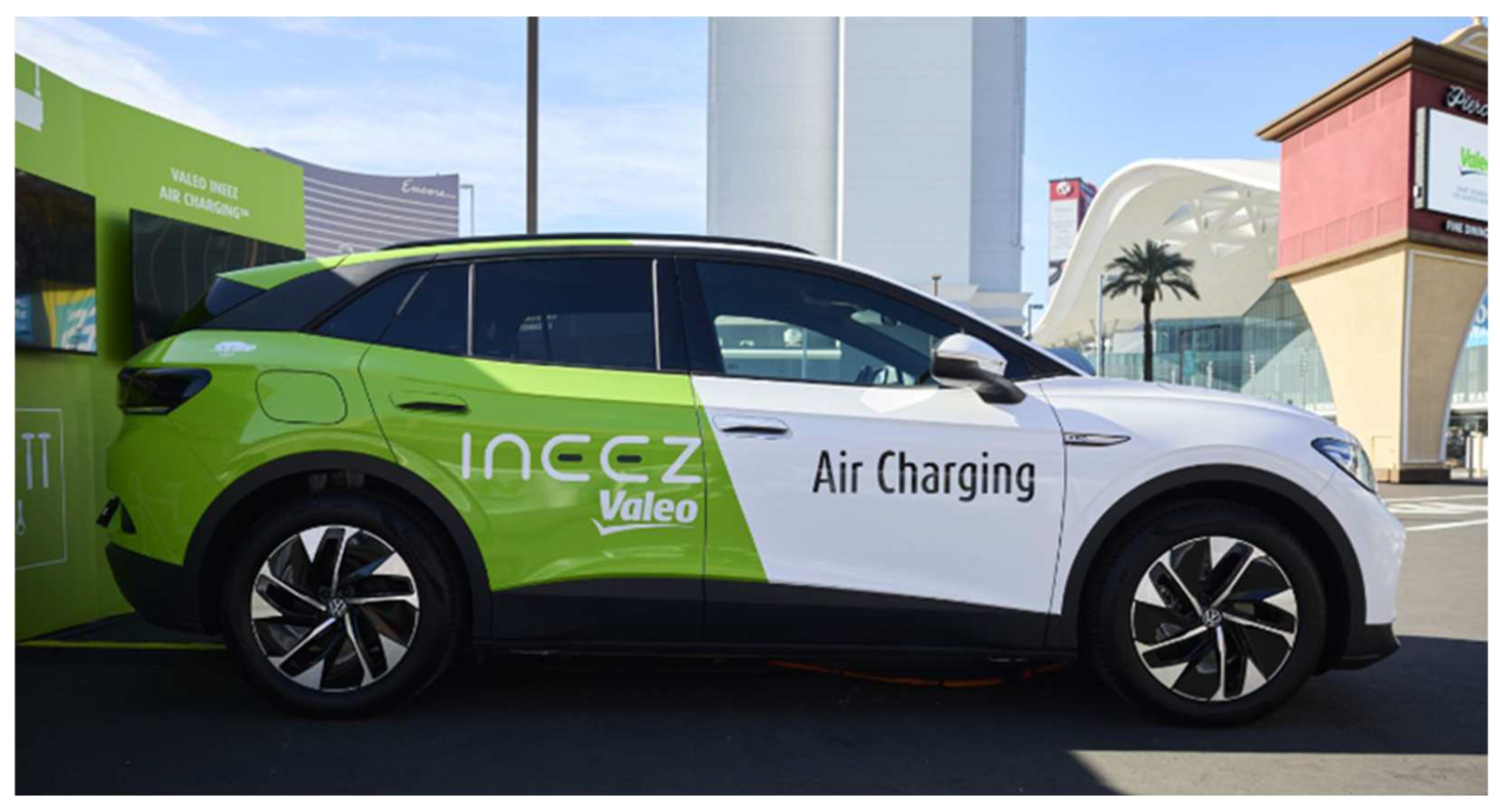
6. Operational Performances on Electric Vehicle Mockup: 350 V 7 kW 3 kHz Bidirectional Wireless Charger

In this section, we present the real-world performance of the low-frequency WPT system equipped with ALIM technology integrated into a Volkswagen ID.4 (Figure 12). This vehicle, demonstrated at CES 2024, Las Vegas, served as a practical testbed to validate our system’s theoretical and experimental results.
Table 2 details the system’s technical specifications, including the operational frequencies, the characteristics of the semiconductors, and the specifications of the charging coils, offering a detailed blueprint of the system setup. We also note that the ID.4 vehicle is equipped with a high-voltage battery, which has a nominal voltage of 350 V.
Field tests concentrated on evaluating the system’s efficiency across both charging and V2X modes, as depicted in Figure 13. The system demonstrated efficiencies of 92.3% in charging mode and 93.4% in reverse mode. Importantly, these efficiencies consistently stayed above 90% when the system delivered more than 500 W to the load. These outcomes not only align with our theoretical models but also highlight the efficiency and reliability of the ALIM strategy across a wide range of operational scenarios. Using the parameters defined in Table 2 and Equation (3), we established that the optimal load impedance is 12.4 Ω in EV charging mode and 15.5 Ω in V2X mode.
The practical demonstration on the Volkswagen ID.4 validates the theoretical assertions, underscoring the commercial feasibility and the ease of use of the low-frequency WPT system with ALIM. This live demonstration evidenced the system’s capacity for high-efficiency power transfer, essential for the broader adoption and acceptance of wireless charging technologies in electric vehicles. By showcasing a robust, adaptable charging solution that aligns with user needs and operational expectations, this real-world application underscores a significant advancement towards the commercialization of efficient and convenient wireless charging systems for EVs.

7. Application Case: 800 V 11 kW 85 kHz Bidirectional Wireless Charger

This section details an implementation and the theoretical performance of the ALIM control strategy for a wireless charger operating with modulated power transfer at a frequency of 85 kHz.

7.1. Circuit Definition and Driving Strategy

The implementation of the ALIM control strategy at the rectification stage necessitates the use of a switching frequency substantially higher than the frequency of currents circulating in the WPT coils. Such a working frequency is incompatible with the circuit depicted in Figure 2 as it generates excessive switching losses at this frequency, leading to a performance that does not meet the expectations of the automotive market.
Figure 14 illustrates a WPT charger circuit capable of implementing the ALIM rectification strategy in both vehicle charging mode and high-frequency V2X mode. This design builds on the interleaved soft-switching Totem-Pole PFC rectifier [32], and its operation is detailed in this section.
During the vehicle-charging phase, transistors QA through QH are configured as a full bridge with a phase shift and operate at a 50% duty cycle. The switching frequency is set to match the WPT energy transfer frequency Fsw. Phase shifts φA and φB are maintained at 0 radians to ensure synchronization of the conduction phases across the transistor pairs QA/QD, QB/QC, QE/QH, and QF/QG. Additionally, a power loop dynamically controls the φC phase shift, as detailed in Section 4.4, focusing on the φ variable.
In the vehicle’s rectification stage, phase shifts φ1 and φ2 are set to π radians to induce sufficient current ripple in ZVS inductor pairs L12/L34 and L56/L78. This configuration ensures ZVS for transistors Q1 to Q8 under all operating voltages and power settings of the charger. Optionally, and to minimize losses when the transistors are turned off, you can connect ZVS capacitors in parallel with them. The switching frequency of the four cells Q1/Q2, Q3/Q4, Q5/Q6, and Q7/Q8 is notably higher than the Fsw, and is designated as Fadapt. The phase shift φ3 is fixed at π/2 radians, leading to a uniform phase shift distribution among these cells, which effectively quadruples the frequency Fadapt from the perspective of the resonant circuit Ls/Cs.
Duty cycles α11 and α12, as well as α21 and α22, are kept nearly identical, with minor real-time adjustments to balance the average current through the ZVS inductor pairs L12/L34 and L56/L78. You may also combine and couple these inductor pairs on the same magnetic core to reduce the number of magnetic components, although this is not the case here. The minimum average values for these duty cycles are set according to the formula Z a d a p t × I b a t t ( t ) 2 × V b a t t . This calculation, which is contingent on the transmitted power and does not typically exceed 50%, accounts for the average battery charging current, Ibatt, thus aiding in lowering the RMS current through the ZVS inductors L12/L34 and L56/L78 relative to the usual average of 50%. The dynamic aspect of the duty cycles α11/α12 and α21/α22 employs a term I s ( t ) × Z a d a p t 2 × V b a t t , applied with both positive and negative coefficients, respectively. This facilitates the generation of the anticipated Vout voltage as outlined in Equation (4), supporting an ALIM rectification strategy similar to that used in Class D amplifiers [33].
I Z V S = 2 × C z v s × V b a t t T d t
The following definitions apply:
CZVS: Natural output capacitance of the switching cell transistors plus optional ZVS capacitor values;
Tdt: Dead time between high-side and low-side PWM driving signals of the switching cell.
In EV charging mode,
D C m i n V b a t t × I b a t t ( t ) 2 × Z a d a p t + I Z V S × 2 × L z v s × F a d a p t V b a t t
In V2X mode,
D C m i n V d c i n × I d c i n ( t ) 2 × Z a d a p t + I Z V S × 2 × L z v s × F a d a p t V d c i n
where Lzvs is the LAB, LCD, LEF, LGH, L12, L34, L56, and L78 ZVS inductors’ value.
Table 3 summarizes the configuration settings for the control variables of the circuit for both vehicle charging mode and V2X mode. The parameter DCmin specified in Equation (12), which is part of the duty cycles of the ALIM rectification, ensures soft switching on the transistors.

7.2. Product Definition

The charger discussed in this section operates under the same electrical environmental constraints as the one presented in Section 5.1, specifically, it is a reversible WPT charger designed for a nominal power of 11 kW and a nominal battery voltage of 800 V. The operating frequency is set at 85 kHz to ensure system interoperability with other automotive WPT chargers [6].

7.3. Sizing Results

In the 85 kHz charger application described here, we choose to operate the ALIM rectification at a frequency of 1.7 MHz to ensure stable emulation of the load impedance. To achieve this frequency, we rely on a π/2 radian phase shift between the four rectification switching cells, each operating at a frequency Fadapt of 425 kHz.
The comprehensive optimization process of the wireless charging system, constrained by several factors, derives the sizing results presented here. These constraints include the use of Litz wire in the coils and the dimensions and onboard mass of the coils, as well as the level of the magnetic field generated around the perimeter of the vehicle, which adheres to the ICNIRP standards for WPT chargers. We based the Litz wire model used in this sizing on a study of a winding geometric configuration similar to that used in our application [34]. The 85 kHz design configuration yields inductors with notably low mass due to their exceptionally compact footprint. Specifically, the diameters of the inductors at the charging station and vehicle side are 32 cm and 24 cm, respectively.
As previously discussed, a WPT-charger-type coupled circuit exhibits an optimal load impedance at which the system operates with maximized energy efficiency, regardless of the power level transmitted and the battery voltage. This optimal impedance can be determined through a frequency analysis on an equivalent circuit, as shown in Figure 3, or with Equation (3) for Series–Series compensation circuits. Using the parameters defined in Table 4 and Equation (3), we established that the optimal load impedance is 9.6 Ω in EV charging mode and 16.5 Ω in V2X mode. Figure 15 illustrates a comparison between this optimal impedance and the equivalent impedance of traditional synchronous rectification, as described by Equation (2). It appears that, at high power, synchronous rectification tends to approach the optimal impedance, though not completely, whereas ALIM rectification imposes the load on an optimized impedance. Figure 16 demonstrates the advantage of our solution at low power, where there is a significant gap between the optimal impedance and the equivalent impedance of synchronous rectification.
Figure 16 presents the expected theoretical efficiencies of the system employing both synchronous rectification and the ALIM strategy for the electrical configuration detailed in Table 4 in both vehicle charging mode and V2X mode. It appears that, at 11 kW, the anticipated performance of both the conventional synchronous rectification and the ALIM strategy is comparable, with each achieving approximately 97% from Vdcin to battery efficiency. However, at lower power levels, such as 1 kW, the ALIM strategy shows a significant advantage, with a difference of approximately 13% in efficiency. This difference is primarily due to the impedance mismatch between the synchronous rectifier and the resonant circuit at reduced power. Based on this observation, it may be beneficial to simplify the vehicle-side electrical circuit with a full-bridge synchronous rectifier when charging predominantly occurs at high power levels, while the V2X mode requires enhanced efficiency performance at lower powers, for example, below 3 kW.
Regarding thermal management, it is essential to assess the cooling benefits and challenges associated with the two rectification strategies.
Figure 17 illustrates the distribution of power losses in the system at both low and high charging powers, utilizing both the conventional synchronous rectification strategy and the ALIM rectification strategy.
For the ALIM rectification strategy, the primary sources of system losses are the electronics, including ZVS inductors and rectification transistors. The system records maximum losses of 15 W per ZVS inductor and 22 W in the low-side rectification transistors. These components can be cooled using conventional methods for discrete components. Additionally, air-cooling can manage losses in the WPT inductors, which do not exceed 53 W.
Conversely, the situation with conventional synchronous rectification is quite different. Electronic components also experience low enough losses for conventional cooling to be considered, with a maximum of 20 W per transistor at the charging station’s inverter. However, the WPT circuit inductance at the charging station significantly increases losses, reaching up to 234 W. Such high losses necessitate more costly and bulky water cooling. In V2X mode, we observe a similar situation, where synchronous rectification at 11 kW transmitted power results in losses of 262 W in the vehicle’s inductance. Unlike with ALIM rectification, synchronous rectification shows a significant imbalance in power dissipation between the two inductances Lp and Ls. This is primarily due to an impedance mismatch between the resonant WPT circuit and the impedance imposed by synchronous rectification. The excessively high impedance of the rectification places the primary circuit in a mode that approximates a primary short-circuit, inducing a high-resonance current. This phenomenon can be exemplified by considering the extreme case of rectification failure with an infinite load impedance, where the primary circuit is nearly in a complete short-circuit, with only the component ESRs limiting the current flow.
Because of the high current flowing through the inverter, there is also an induced RMS voltage across the compensation capacitors. In the 11 kW vehicle charging mode, the expected voltage on capacitor Cp is 2134 Vrms in the case of synchronous rectification, compared to 1011 Vrms using the ALIM technique. This variance significantly affects the size, cost, and associated power losses of the component.
To elucidate the circuit’s operational behavior at 85 kHz, we illustrate the primary currents in the rectification stage as per the ALIM strategy in Figure 18 according to the electrical configuration detailed in Table 4. As depicted, the current through L12 is a superposition of the 85 kHz sinusoidal current Is(t)/2 and a 425 kHz ripple current. The purpose of this ripple current is to ensure the transistors conduct with a negative drain current. This design approach, following Equations (11) and (12), guarantees zero switching ON losses. Additionally, the optional ZVS capacitors in parallel with the transistors ensure that the switching OFF transitions are also lossless [35].
Given a received battery power of 11 kW and an RMS current Is of 33.8 A, we conclude that the load impedance seen by the secondary coupled circuit Ls/Cs is at the optimal value of 9.6 Ω, as previously determined.

8. Conclusions

This study has comprehensively demonstrated the effectiveness of the ALIM strategy in enhancing the efficiency and flexibility of WPT systems for electric vehicles across both standard low frequencies and at 85 kHz. Unlike the synchronous rectification technic, ALIM has proven particularly advantageous at lower power levels, which is essential for V2X applications. In these scenarios, ALIM maintains high efficiency, pivotal for technologies such as Vehicle-to-Grid and Vehicle-to-Home technologies where low-power operation is required. This capability underscores the strategy’s potential in supporting a range of operational demands without compromising performance.
Moreover, our findings have revealed significant thermal management benefits associated with the ALIM strategy. By substantially reducing losses in the WPT inductors, the system demands less from cooling solutions, simplifying thermal management and enhancing overall system reliability and durability. This reduction in thermal stress is critical for sustaining system efficiency and is a testament to the inherent advantages of implementing ALIM, particularly when contrasted with traditional rectification methods that may induce higher losses and require more complex cooling strategies.
Looking forward, exploring alternative compensation circuits beyond the classical Series–Series configuration could provide opportunities to further enhance system performance. Although the Series–Series setup offers simplicity and cost effectiveness, configurations such as Series–Parallel or Parallel–Parallel might yield improvements in specific scenarios, albeit potentially at a higher cost and complexity.
Additionally, future research should consider alternative inductor geometries beyond the traditional circular configuration explored in this publication. Different geometric configurations of the inductors could potentially improve system performance by optimizing the magnetic field distribution and coupling efficiency, which could be particularly beneficial in complex installation environments or varied vehicle designs.
Further, refining the control strategies within ALIM systems to better adapt to varying alignment, ground clearance, and battery voltage will be crucial. The application of advanced predictive and adaptive algorithms could improve the real-time responsiveness of WPT systems, optimizing energy transfer under fluctuating operational conditions.
In summary, the ALIM strategy represents a significant step forward in the development of efficient, flexible, and economically viable wireless charging solutions for electric vehicles. It promises substantial improvements in system performance across a variety of charging conditions, making it a crucial component in the transition towards an electrified, efficient transportation ecosystem. As this technology continues to evolve, it will play a pivotal role in the broader adoption and optimization of electric vehicle infrastructure.

Funding

This research was funded by Valeo. The APC was funded by Valeo.

Data Availability Statement

The data supporting the reported results are confidential and cannot be shared due to privacy or ethical restrictions.

Conflicts of Interest

The author declares that this study received funding from Valeo. The funder had the following involvement with the study: providing materials and the time of team members to prepare the mechanical and electrical aspects of the demonstration vehicle.

References

  1. Kashani, S.A.; Soleimani, A.; Khosravi, A.; Mirsalim, M. State-of-the-Art Research on Wireless Charging of Electric Vehicles Using Solar Energy. Energies 2022, 16, 282. [Google Scholar] [CrossRef]
  2. Eltamaly, A.M. Optimal Dispatch Strategy for Electric Vehicles in V2G Applications. Smart Cities 2023, 6, 3161–3191. [Google Scholar] [CrossRef]
  3. Fotopoulou, M.; Rakopoulos, D.; Blanas, O. Day Ahead Optimal Dispatch Schedule in a Smart Grid Containing Distributed Energy Resources and Electric Vehicles. Sensors 2021, 21, 7295. [Google Scholar] [CrossRef] [PubMed]
  4. Bian, H.; Ren, Q.; Guo, Z.; Zhou, C. Optimal Scheduling of Integrated Energy System Considering Electric Vehicle Battery Swapping Station and Multiple Uncertainties. World Electr. Veh. J. 2024, 15, 170. [Google Scholar] [CrossRef]
  5. Palani, G.; Sengamalai, U.; Vishnuram, P.; Nastasi, B. Challenges and Barriers of Wireless Charging Technologies for Electric Vehicles. Energies 2023, 16, 2138. [Google Scholar] [CrossRef]
  6. SAE Standard J2954; SAE J2954 Wireless Power Transfer for Light-Duty Plug-In/Electric Vehicles and Alignment Methodology. SAE International: Warrendale, PA, USA, 2020.
  7. Lee, T.-E.; Huang, T.-H. Hybrid Impedance Matching Strategy for Wireless Charging System. In Proceedings of the 2016 IEEE Vehicle Power and Propulsion Conference (VPPC), Hangzhou, China, 17–20 October 2016. [Google Scholar]
  8. Yang, H.; Wu, C.; Chen, T. Efficiency Improvement for Wireless Power Transfer System via a Nonlinear Resistance Matching Network. Electronics 2023, 12, 1341. [Google Scholar] [CrossRef]
  9. Xu, Y.; Zhang, Y.; Wu, T. Wireless Power Transfer Efficiency Optimization Tracking Method Based on Full Current Mode Impedance Matching. Sensors 2024, 24, 2917. [Google Scholar] [CrossRef] [PubMed]
  10. Sun, Z.; Hu, G.; Wang, Y.; Guan, Y.; Xu, D. Analysis and Design of Configurable Rectifier with Compensated Near-Zero Impedance Angle for Megahertz Wireless Power Transfer. IEEE Trans. Ind. Electron. 2024, 71, 4596–4606. [Google Scholar] [CrossRef]
  11. Bentalhik, I.; Lassioui, A.; EL Fadil, H.; Bouanou, T.; Rachid, A.; EL Idrissi, Z.; Hamed, A.M. Analysis, Design and Realization of a Wireless Power Transfer Charger for Electric Vehicles: Theoretical Approach and Experimental Results. World Electr. Veh. J. 2022, 13, 121. [Google Scholar] [CrossRef]
  12. Waldron, J.; Rodrigues, L.; Deb, S.; Gillott, M.; Naylor, S.; Rimmer, C. Exploring Opportunities for Vehicle-to-Grid Implementation through Demonstration Projects. Energies 2024, 17, 1549. [Google Scholar] [CrossRef]
  13. Osawa, J. Evaluation of Technological Configurations of Residential Energy Systems Considering Bidirectional Power Supply by Vehicles in Japan. Energies 2024, 17, 1574. [Google Scholar] [CrossRef]
  14. Sullivan, C. Cost-constrained selection of strand diameter and number in a litz-wire transformer winding. IEEE Trans. Power Electron. 2001, 16, 281–288. [Google Scholar] [CrossRef]
  15. Sabki, S.A.; Tan, N.M.L. Wireless power transfer for electric vehicle. In Proceedings of the 2014 IEEE 8th International Power Engineering and Optimization Conference (PEOCO2014), Langkawi, Malaysia, 24–25 March 2014; pp. 41–46. [Google Scholar]
  16. Wen, H.; Wang, P.; Li, J.; Yang, J.; Zhang, K.; Yang, L.; Zhao, Y.; Tong, X. Improving the Misalignment Tolerance of Wireless Power Transfer System for AUV with Solenoid-Dual Combined Planar Magnetic Coupler. J. Mar. Sci. Eng. 2023, 11, 1571. [Google Scholar] [CrossRef]
  17. Venkatesan, M.; Rajamanickam, N.; Vishnuram, P.; Bajaj, M.; Blazek, V.; Prokop, L.; Misak, S. A Review of Compensation Topologies and Control Techniques of Bidirectional Wireless Power Transfer Systems for Electric Vehicle Applications. Energies 2022, 15, 7816. [Google Scholar] [CrossRef]
  18. Shu, X.; Wu, G.; Jiang, Y. Comparative Analysis of SS, SP, PP and PS Topologies for Magnetic Coupled Wireless Power Transfer System Composed of the Negative Resistor. Energies 2023, 16, 7336. [Google Scholar] [CrossRef]
  19. Feng, H.; Wang, D. Minimizing Material Usage for Efficient and Compact Coil in Wireless Charging System of Electric Vehicles. IEEE Trans. Transp. Electrif. 2023, 10, 2886–2898. [Google Scholar] [CrossRef]
  20. Sha, L.; Liu, J.; Chen, Z. Research on Evaluation Method of Electric Vehicle Wireless Charging Interoperability Based on Two Parameter Representation. Processes 2022, 10, 1591. [Google Scholar] [CrossRef]
  21. Liu, W.; Hu, C.; Xiang, L. A Multimodal Modulation Scheme for Electric Vehicles’ Wireless Power Transfer Systems, Based on Secondary Impedance. Electronics 2022, 11, 3055. [Google Scholar] [CrossRef]
  22. Oeder, C.; Duerbaum, T. ZVS investigation of llc converters based on FHA assumptions. In Proceedings of the 2013 Twenty-Eighth Annual IEEE Applied Power Electronics Conference and Exposition (APEC), Long Beach, CA, USA, 17–21 March 2013; pp. 2643–2648. [Google Scholar]
  23. Sucameli, M.; Adragna, C. LLC Resonant Converters as Isolated Power Factor Corrector Pre-Regulators—Analysis and Performance Evaluation. Energies 2023, 16, 7114. [Google Scholar] [CrossRef]
  24. Steigerwald, R.L. A comparison of half-bridge resonant converter topologies. In Proceedings of the 1987 2nd IEEE Applied Power Electronics Conference and Exposition, San Diego, CA, USA, 2–6 March 1987; pp. 135–144. [Google Scholar]
  25. Zhou, X.; Wang, J.; Yang, L. A Light-Load Efficiency Improvement Technique for an Inductive Power Transfer System through a Reconfigurable Circuit. Energies 2024, 17, 3024. [Google Scholar] [CrossRef]
  26. El Baghdadi, M.; Benomar, Y.; Hegazy, O.; Yang, Y.; Van Mierlo, J. Design approach and interoperability analysis of wireless power transfer systems for vehicular applications. In Proceedings of the 2016 18th European Conference on Power Electronics and Applications (EPE’16 ECCE Europe), Karlsruhe, Germany, 5–9 September 2016; pp. 1–11. [Google Scholar]
  27. Jimoh, B.A.; Roşu, Ş.-G. Single-Phase AC-DC PFC Converters for EV Chargers: An Overview. In Proceedings of the 2023 15th International Conference on Electronics, Computers and Artificial Intelligence (ECAI), Bucharest, Romania, 29–30 June 2023; pp. 1–6. [Google Scholar]
  28. Nisch, A.; Kloeffer, C.; Weigold, J.; Wondrak, W.; Schweikert, C.; Beaurenaut, L. Effects of a SiC TMOSFET Tractions Inverters on the Electric Vehicle Drivetrain. In Proceedings of the PCIM Europe 2018; International Exhibition and Conference for Power Electronics, Intelligent Motion, Renewable Energy and Energy Management, Nuremberg, Germany, 5–7 June 2018; pp. 1–8. [Google Scholar]
  29. Campi, T.; Cruciani, S.; Maradei, F.; Feliziani, M. Magnetic Field during Wireless Charging in an Electric Vehicle According to Standard SAE J2954. Energies 2019, 12, 1795. [Google Scholar] [CrossRef]
  30. Lv, C.; Liu, J.; Zhang, Y.; Yin, J.; Cao, R.; Li, Y.; Liu, X. A Method to Characterize the Shrinking of Safe Operation Area of Metallized Film Capacitor Considering Electrothermal Coupling and Aging in Power Electronics Applications. IEEE Trans. Ind. Electron. 2022, 70, 1993–2002. [Google Scholar] [CrossRef]
  31. Li, W.; Diao, L.; Mei, W.; Dongye, Z.; Qin, X.; Jin, Z. Optimized Resonant Network Design for High Energy Transfer Efficiency of the WPT System. Electronics 2023, 12, 1984. [Google Scholar] [CrossRef]
  32. Huang, L.; Yao, W.; Lu, Z. Interleaved totem-pole bridgeless PFC rectifier with ZVS and low input current ripple. In Proceedings of the 2015 IEEE Energy Conversion Congress and Exposition (ECCE), Montreal, QC, Canada, 20–24 September 2015; pp. 166–171. [Google Scholar]
  33. Yang, L.; Xu, L.; Yang, T.; Zhang, B. Class D Power Amplifier for Audio Beam System. In Proceedings of the 2007 International Conference on Mechatronics and Automation, Harbin, China, 5–8 August 2007; pp. 3469–3474. [Google Scholar]
  34. Kawahara, S.; Umetani, K.; Hiraki, E. AC resistance Prediction of Litz Wire Planer Spiral Coil Based on Litz wire Loss Model. In Proceedings of the 2020 23rd International Conference on Electrical Machines and Systems (ICEMS), Hamamatsu, Japan, 24–27 November 2020; pp. 1541–1546. [Google Scholar]
  35. Zimoch, P.; Kasprzak, M.; Kierepka, K. Influence of MOSFET Parasitic Capacitance on the Operation of Interleaved ZVS Boost Converters. Energies 2020, 13, 6130. [Google Scholar] [CrossRef]
Figure 1. Standard WPT compensation circuits.
Electronics 13 02720 g001
Figure 2. Bidirectional Series–Series-compensated WPT charger circuit with ALIM rectification for low-frequency operation.
Electronics 13 02720 g002
Figure 3. AC equivalent circuit of an SS-compensated WPT charger.
Electronics 13 02720 g003
Figure 4. Secondary S-S-compensated WPT AC equivalent circuit with load voltage control.
Electronics 13 02720 g004
Figure 5. EV rectification circuit.
Electronics 13 02720 g005
Figure 6. Rectification circuit electrical waveforms with active load matching strategy.
Electronics 13 02720 g006
Figure 7. Proposed control law for WPT charger with active load matching strategy.
Electronics 13 02720 g007
Figure 8. Theoretical efficiency at 25 °C in charge and V2X mode with ALIM rectification strategy, an airgap of 100 mm, and Vbatt = 800 V.
Electronics 13 02720 g008
Figure 9. Efficiency comparison at 25 °C in charge mode with and without ALIM rectification strategy, an airgap of 100 mm, and Vbatt = 800 V.
Electronics 13 02720 g009
Figure 10. System efficiency with drop in Cs parameter of 25%.
Electronics 13 02720 g010
Figure 11. System efficiency with drop in Lp, Ls, and coupling parameters of 15%.
Electronics 13 02720 g011
Figure 12. Inductive charging of the ID.4 demonstration vehicle equipped with the Valeo ALIM charger during CES 2024 in Las Vegas.
Electronics 13 02720 g012
Figure 13. EV Mockup charging and reverse mode measured efficiency at 25 °C with ALIM rectification strategy, an airgap of 100 mm, and ~350 V on EV battery.
Electronics 13 02720 g013
Figure 14. Bidirectional Series–Series-compensated WPT charger circuit with ALIM rectification for high-frequency operation.
Electronics 13 02720 g014
Figure 15. Synchronous rectification impedance and ALIM circuit impedance at 85 kHz in EV charging mode for an EV battery voltage at 800 V.
Electronics 13 02720 g015
Figure 16. Efficiencies of 800 V 11 kW 85 kHz WPT charger system at 25 °C and Vbatt = 800 V.
Electronics 13 02720 g016
Figure 17. Power loss distribution of 800 V 11 kW 85 kHz WPT charger at 25 °C in charging operation [W].
Electronics 13 02720 g017
Figure 18. Circuit electrical simulation waveforms with ALIM strategy on 85 kHz ALIM circuit in EV charging mode at 11 kW and Vbatt = 800 V.
Electronics 13 02720 g018
Table 1. Sizing results of 800 V 11 kW WPT charger.
AttributeValue
Operating frequenciesFsw = 7 kHz
Fadapt = 140 kHz
EV-side and charging-station-side transistors1200 V 12 mΩ SiC MOSFET
Primary capacitor390 nF ESR ~5 mΩ at 7 kHz
Secondary capacitor460 nF ESR ~5 mΩ at 7 kHz
Charging station coil1.324 mH ESR 587 mΩ at 7 kHz 100 mm airgap
Magnetic core + winding total weight 6.8 kg
EV-side coil1.117 mH ESR 456 mΩ at 7 kHz 100 mm airgap
Magnetic core + winding total weight 4.9 kg
Coupling factor at 100 mm airgap45.5%
Total control and driving power5 W
Table 2. Sizing results of 350 V 7 kW WPT charger.
AttributeValue
Operating frequenciesFsw = 2.8 kHz
Fadapt = 100 kHz
EV-side and charging-station-side transistors750 V 11 mΩ SiC MOSFET
Primary capacitor2 µF ESR ~10 mΩ
Secondary capacitor2.9 µF ESR ~10 mΩ
Charging station coil1.8 mH ESR 437 mΩ at 2.8 kHz 100 mm airgap
Magnetic core + winding total weight 3.7 kg
EV-side coil1.2 mH ESR 349 mΩ at 2.8 kHz 100 mm airgap
Magnetic core + winding total weight 2.3 kg
Coupling factor at 100mm airgap53.5%
Total control and driving power5 W
Table 3. Parameters setting in WPT charger circuit with ALIM rectification for high-frequency operation.
Operating Mode →EV Charging ModeV2X Mode
↓ Control Variables
Charging station
side
Duty cycles αA1/αA250% Z a d a p t × I d c i n ( t ) 2 × V d c i n + I p ( t ) × Z a d a p t 2 × V d c i n + D C m i n *
Duty cycles αB1/αB250% Z a d a p t × I d c i n ( t ) 2 × V d c i n I p ( t ) × Z a d a p t 2 × V d c i n + D C m i n *
Phase shift φA0 rdπ rd
Phase shift φB0 rdπ rd
Phase shift φCPhase shift power loop controlπ/2 rd
Operating
frequency
FswFadapt
EV sideDuty cycles α11/α12 Z a d a p t × I b a t t ( t ) 2 × V b a t t + I s ( t ) × Z a d a p t 2 × V b a t t + D C m i n *50%
Duty cycles α21/α22 Z a d a p t × I b a t t ( t ) 2 × V b a t t I s ( t ) × Z a d a p t 2 × V b a t t + D C m i n *50%
Phase shift φ1π rd0 rd
Phase shift φ2π rd0 rd
Phase shift φ3π/2 rdPhase shift power loop control
Operating
frequency
FadaptFsw
* DCmin is an offset of minimum duty cycle value required to perform ZVS switching ON operation on the rectification transistors. Equation (12) gives its definition.
Table 4. Sizing results of 800 V 11 kW 85 kHz WPT charger.
AttributeValue
Operating frequenciesFsw = 85 kHz
Fadapt = 425 kHz
EV-side and charging-station-side transistors1200 V 12 mΩ SiC MOSFET
ZVS inductors2 µH 150 A ESR DC ~1.5 mΩ/425 kHz ~2.25 mΩ
ZVS capacitors2 nF 1200 V ~5 mΩ at 425 kHz
Primary capacitor50 nF ESR ~10 mΩ at 85 kHz
Secondary capacitor23 nF ESR ~10 mΩ at 85 kHz
Charging station coil154 µH ESR 71.8 mΩ at 85 kHz 100 mm airgap
Magnetic core + winding total weight 5.06 kg
EV-side coil70.5 µH ESR 42.4 mΩ at 85 kHz 100 mm airgap
Magnetic core + winding total weight 1.04 kg
Coupling factor at 100 mm airgap22.6%
Total control and driving power16.3 W for ALIM rectification/5.4 W for synchronous rectification
Disclaimer/Publisher’s Note: The statements, opinions and data contained in all publications are solely those of the individual author(s) and contributor(s) and not of MDPI and/or the editor(s). MDPI and/or the editor(s) disclaim responsibility for any injury to people or property resulting from any ideas, methods, instructions or products referred to in the content.

