
Dual-Band MIMO Antenna for n79 and sub-7 GHz Smartphone Applications

 ,
,  ,
,  and
and
Abstract
1. Introduction
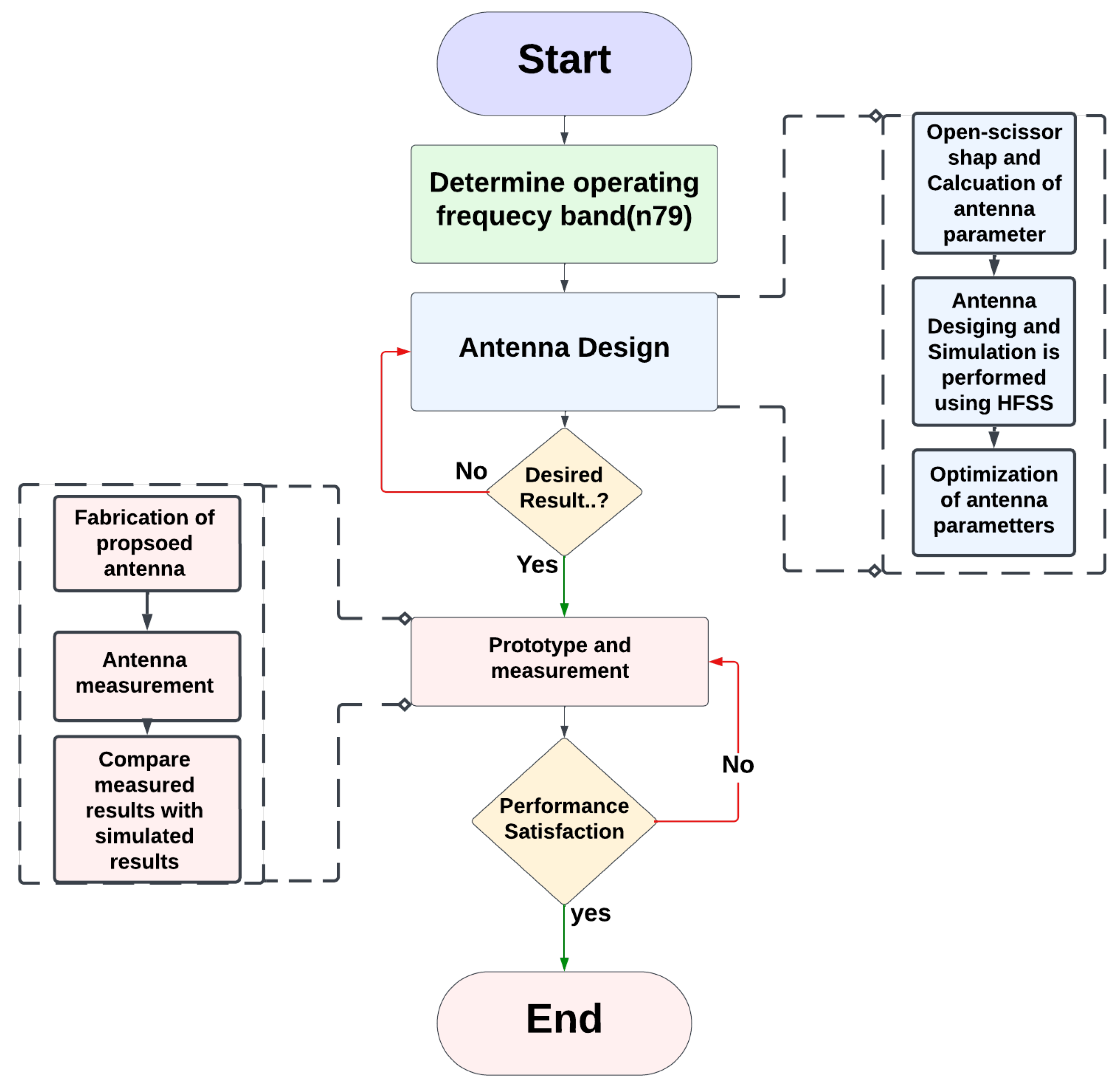
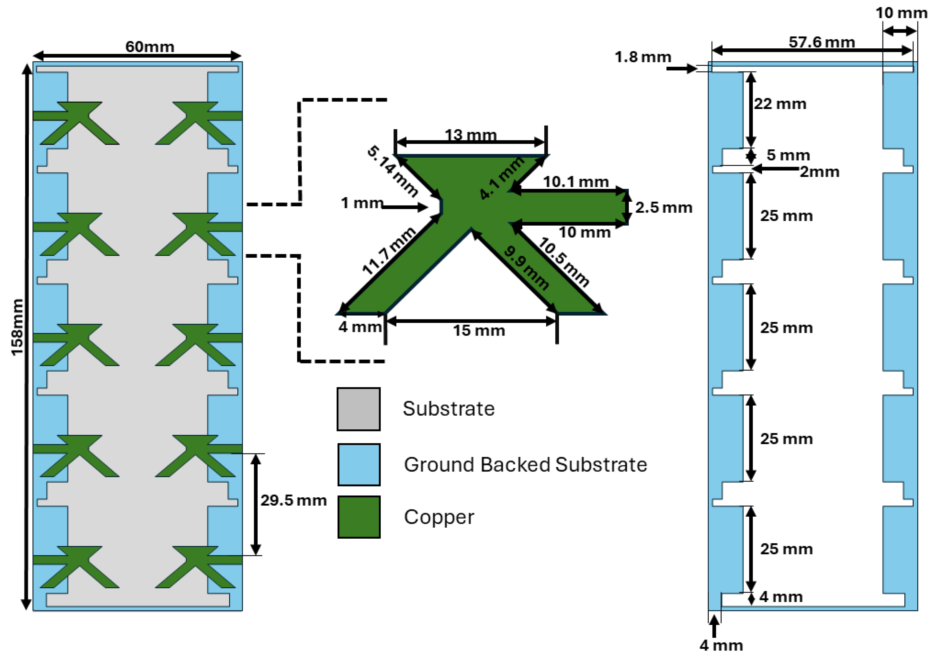
2. Antenna Design
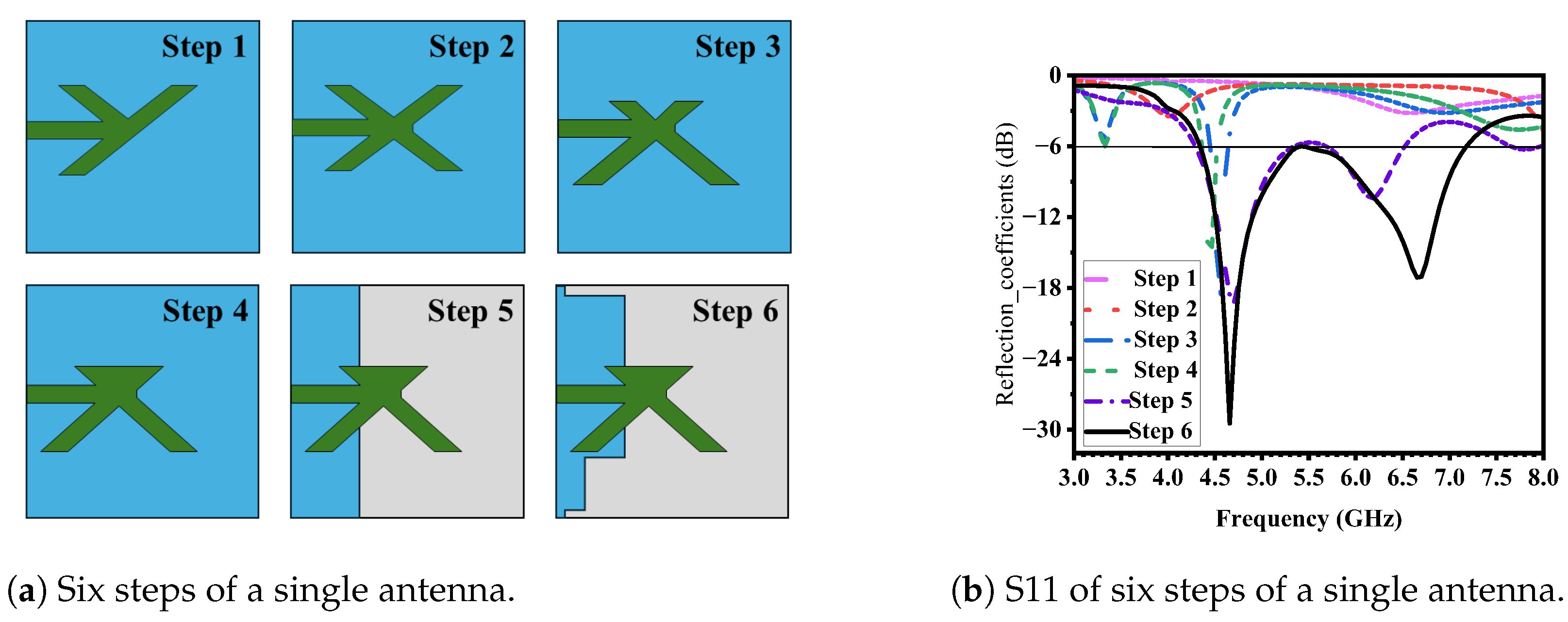
Parametric Analysis
- Step 01:
- Designing a Y-shaped antenna element with the full ground.
- Step 02:
- Designing an X-shaped antenna element with the full ground.
- Step 03:
- The slight shift of an X-shaped antenna to an open scissor-shaped antenna.
- Step 04:
- An open scissor lower section is filled while the ground is kept full.
- Step 05:
- In this step, the lower section filled open scissor using a partial ground shows some good results.
- Step 06:
- Finally, two slots were used to achieve the desired results.
3. Results and Discussion
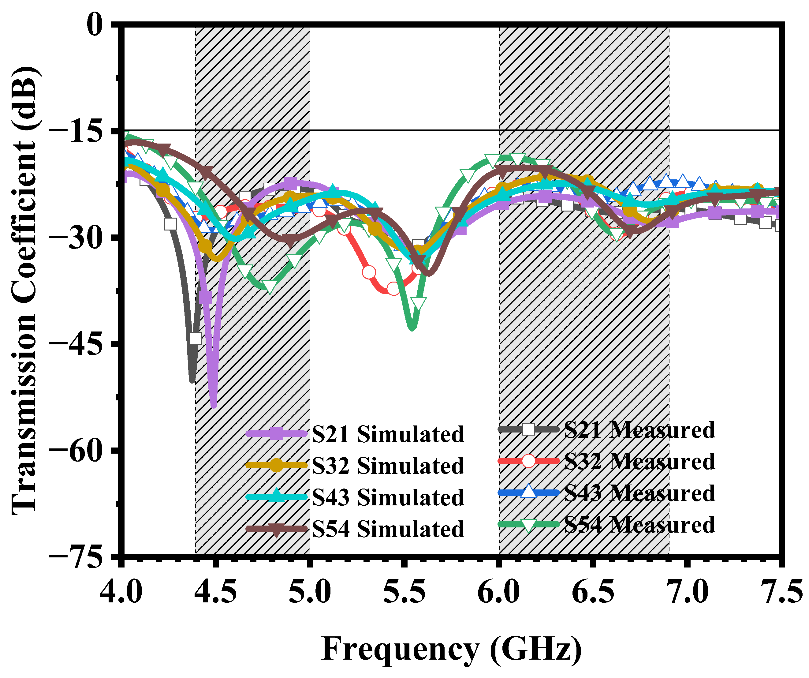
3.1. S-Parameters
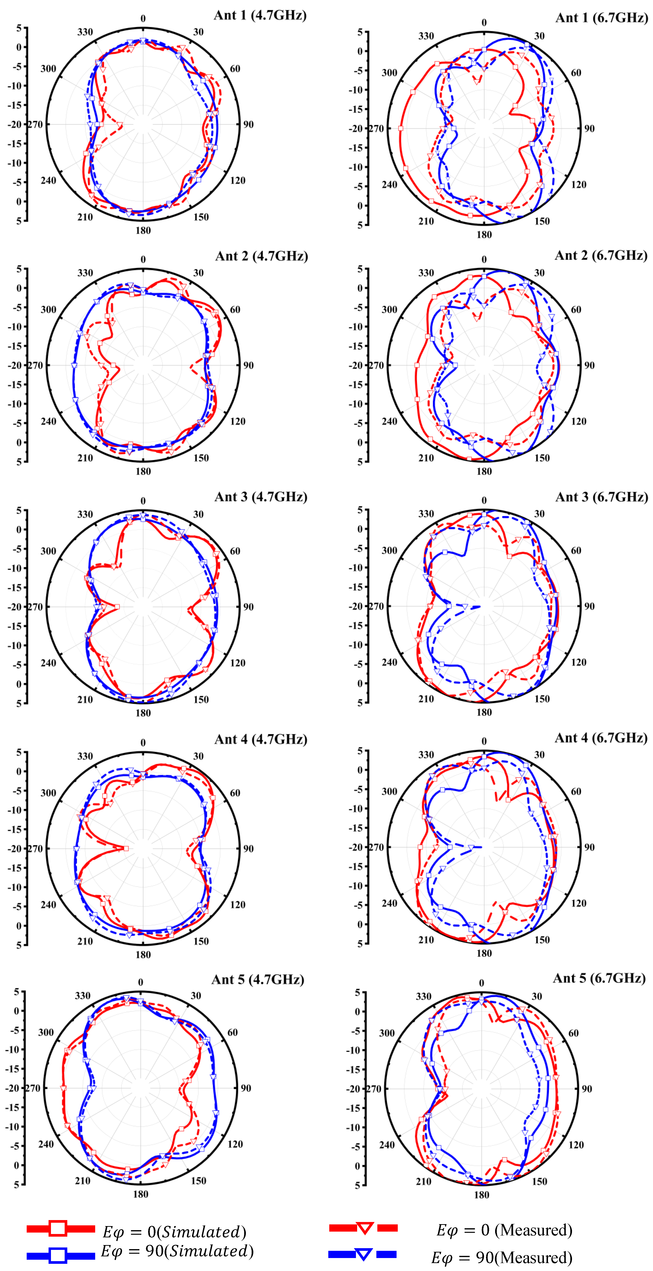
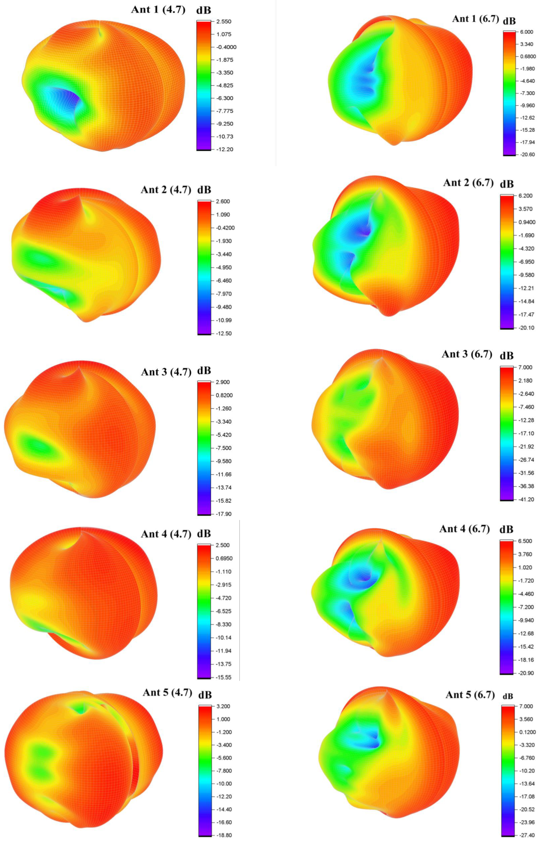
3.2. Radiation Pattern
3.3. MIMO Performance Parameters
3.3.1. Envelope Correlation Coefficient (ECC)
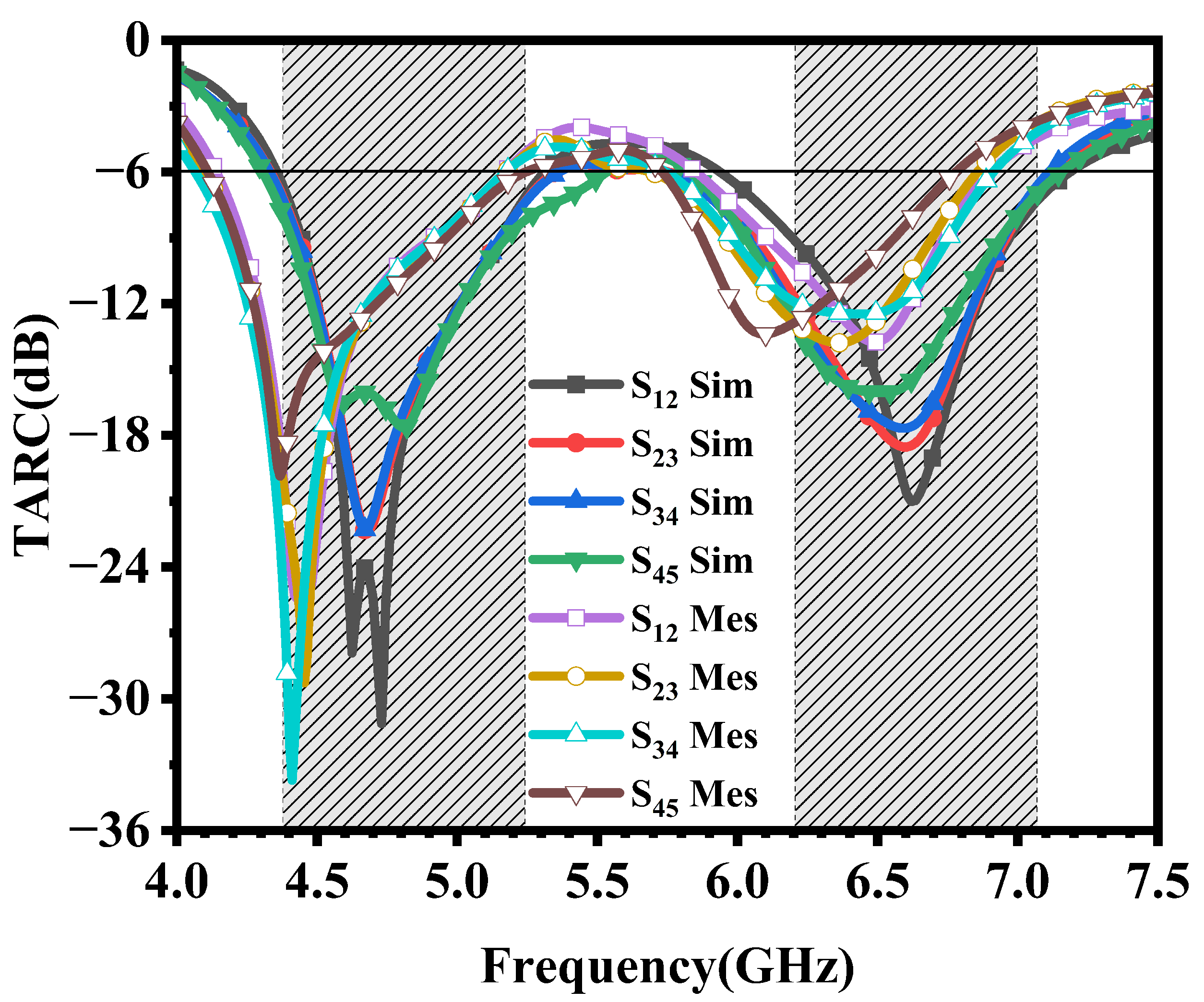
3.3.2. Total Active Reflection Coefficient (TARC)
3.3.3. Mean Effective Gain (MEG)
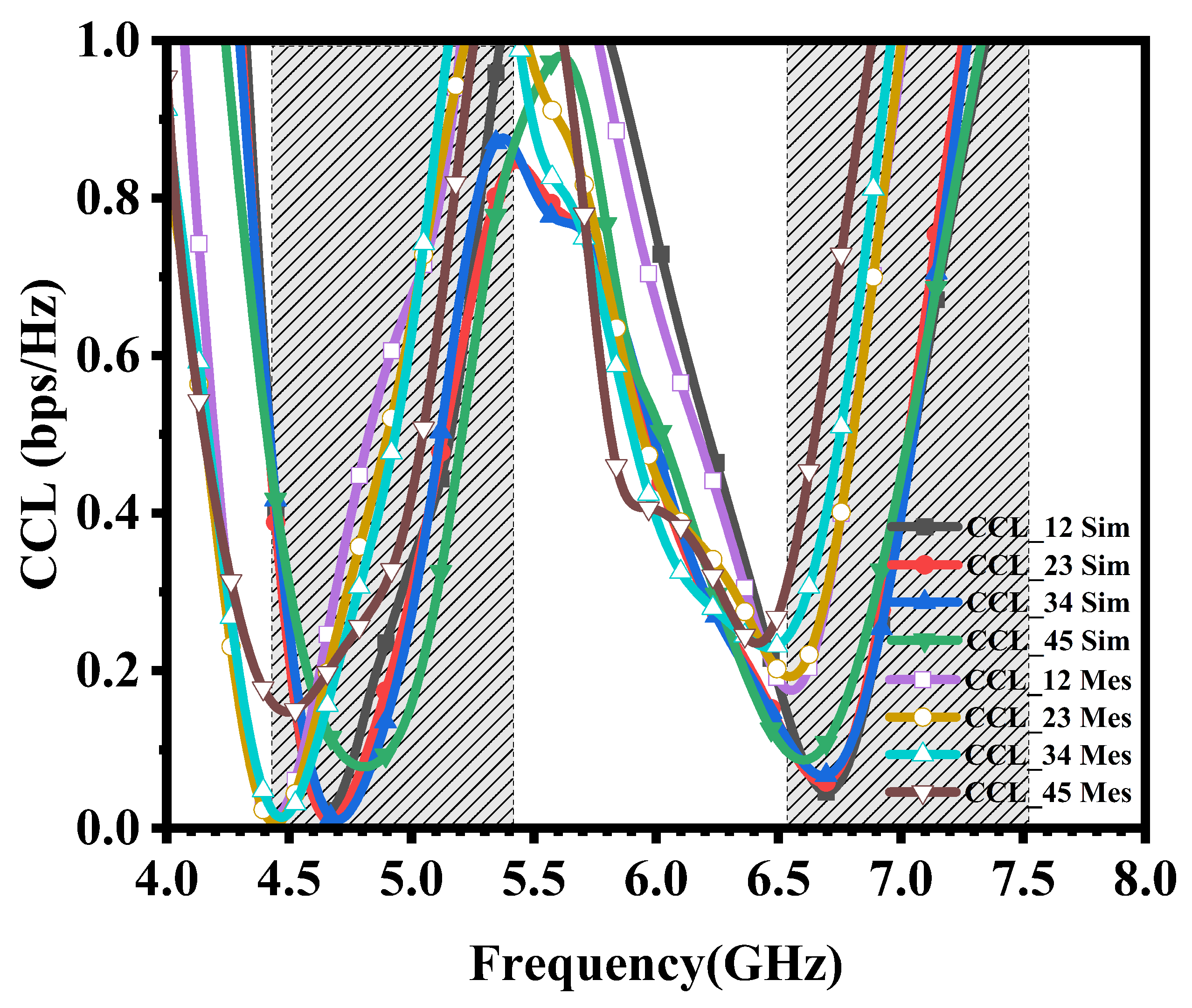
3.3.4. Channel Capacity Loss (CCL)
4. Conclusions
Author Contributions
Funding
Data Availability Statement
Conflicts of Interest
References
- Lu, L.; Li, G.Y.; Swindlehurst, A.L.; Ashikhmin, A.; Zhang, R. An overview of massive MIMO: Benefits and challenges. IEEE J. Sel. Top. Signal Process. 2014, 8, 742–758. [Google Scholar] [CrossRef]
- Larsson, E.G.; Edfors, O.; Tufvesson, F.; Marzetta, T.L. Massive MIMO for next generation wireless systems. IEEE Commun. Mag. 2014, 52, 186–195. [Google Scholar] [CrossRef]
- Li, Y.; Sim, C.Y.D.; Luo, Y.; Yang, G. Multiband 10-antenna array for sub-6 GHz MIMO applications in 5-G smartphones. IEEE Access 2018, 6, 28041–28053. [Google Scholar] [CrossRef]
- Wong, K.L.; Lin, B.W.; Li, B.W.Y. Dual-band dual inverted-F/loop antennas as a compact decoupled building block for forming eight 3.5/5.8-GHz MIMO antennas in the future smartphone. Microw. Opt. Technol. Lett. 2017, 59, 2715–2721. [Google Scholar] [CrossRef]
- Li, Y.; Sim, C.Y.D.; Luo, Y.; Yang, G. 12-Port 5G massive MIMO antenna array in sub-6GHz mobile handset for LTE bands 42/43/46 applications. IEEE Access 2017, 6, 344–354. [Google Scholar] [CrossRef]
- Guo, J.; Cui, L.; Li, C.; Sun, B. Side-edge frame printed eight-port dual-band antenna array for 5G smartphone applications. IEEE Trans. Antennas Propag. 2018, 66, 7412–7417. [Google Scholar] [CrossRef]
- Li, Y.; Yang, G. Dual-mode and triple-band 10-antenna handset array and its multiple-input multiple-output performance evaluation in 5G. Int. J. RF Microw. Comput. Aided Eng. 2019, 29, e21538. [Google Scholar] [CrossRef]
- Sim, C.Y.D.; Liu, H.Y.; Huang, C.J. Wideband MIMO antenna array design for future mobile devices operating in the 5G NR frequency bands n77/n78/n79 and LTE band 46. IEEE Antennas Wirel. Propag. Lett. 2020, 19, 74–78. [Google Scholar] [CrossRef]
- Sun, L.; Li, Y.; Zhang, Z.; Feng, Z. Wideband 5G MIMO antenna with integrated orthogonal-mode dual-antenna pairs for metal-rimmed smartphones. IEEE Trans. Antennas Propag. 2020, 68, 2494–2503. [Google Scholar] [CrossRef]
- Sun, L.; Li, Y.; Zhang, Z. Wideband decoupling of integrated slot antenna pairs for 5G smartphones. IEEE Trans. Antennas Propag. 2021, 69, 2386–2391. [Google Scholar] [CrossRef]
- Li, Y.; Zhao, Z.; Tang, Z.; Yin, Y. A low-profile, dual-band filtering antenna with high selectivity for 5G sub-6 GHz applications. Microw. Opt. Technol. Lett. 2019, 61, 2282–2287. [Google Scholar] [CrossRef]
- Lin, Z.; Lin, M.; Champagne, B.; Zhu, W.-P.; Al-Dhahir, N. Secrecy-Energy Efficient Hybrid Beamforming for Satellite-Terrestrial Integrated Networks. IEEE Trans. Commun. 2021, 69, 6345–6360. [Google Scholar] [CrossRef]
- Lin, Z.; Niu, H.; An, K.; Wang, Y.; Zheng, G.; Chatzinotas, S.; Hu, Y. Refracting RIS-Aided Hybrid Satellite-Terrestrial Relay Networks: Joint Beamforming Design and Optimization. IEEE Trans. Aerosp. Electron. Syst. 2022, 58, 3717–3724. [Google Scholar] [CrossRef]
- Li, Y.; Luo, Y.; Yang, G. High-isolation 3.5 GHz eight-antenna mimo array using balanced open-slot antenna element for 5G smartphones. IEEE Trans. Antennas Propag. 2019, 67, 3820–3830. [Google Scholar] [CrossRef]
- Chang, L.; Yu, Y.; Wei, K.; Wang, H. Orthogonally polarized dual antenna pair with high isolation and balanced high performance for 5G mimo smartphone. IEEE Trans. Antennas Propag. 2020, 68, 3487–3495. [Google Scholar] [CrossRef]
- Cheng, B.; Du, Z. A wideband low-profile microstrip mimo antenna for 5G mobile phones. IEEE Trans. Antennas Propag. 2021, 70, 1476–1481. [Google Scholar] [CrossRef]
- Babashah, H.; Hassani, H.R.; Mohammad-Ali-Nezhad, S. A compact uwb printed monopole mimo antenna with mutual coupling reduction. Prog. Electromagn. Res. C 2019, 91, 55–67. [Google Scholar] [CrossRef]
- Sun, L.; Li, Y.; Zhang, Z.; Iskander, M.F. A compact planar omnidirectional mimo array antenna with pattern phase diversity using folded dipole element. IEEE Trans. Antennas Propag. 2018, 67, 1688–1696. [Google Scholar] [CrossRef]
- Jaglan, N.; Gupta, S.D.; Kanaujia, B.K.; Sharawi, M.S. 10 element sub-6-GHz multi-band double-t based mimo antenna system for 5G smartphones. IEEE Access 2021, 9, 118662–118672. [Google Scholar] [CrossRef]
- Pei, T.; Zhu, L.; Wang, J.; Wu, W. A low-profile decoupling structure for mutual coupling suppression in mimo patch antenna. IEEE Trans. Antennas Propag. 2021, 69, 6145–6153. [Google Scholar] [CrossRef]
- Hei, Y.Q.; He, J.G.; Li, W.T. Wideband decoupled 8-element mimo antenna for 5G mobile terminal applications. IEEE Antennas Wirel. Propag. Lett. 2021, 20, 1448–1452. [Google Scholar] [CrossRef]
- Hu, W.; Liu, X.; Gao, S.; Wen, L.-H.; Qian, L.; Feng, T.; Xu, R.; Fei, P.; Liu, Y. Dual-band ten-element mimo array based on dual-mode ifas for 5G terminal applications. IEEE Access 2019, 7, 178476–178485. [Google Scholar] [CrossRef]
- Behdad, N.; Sarabandi, K. Dual-band reconfigurable antenna with a very wide tunability range. IEEE Trans. Antennas Propag. 2006, 54, 409–416. [Google Scholar] [CrossRef]
- Zaidi, A.; Awan, W.A.; Hussain, N.; Baghdad, A. A wide and tri-band flexible antennas with independently controllable notch bands for sub-6-GHz communication system. Radioengineering 2020, 29, 44–51. [Google Scholar] [CrossRef]
- Zahid, M.N.; Gaofeng, Z.; Kiani, S.H.; Rafique, U.; Abbas, S.M.; Alibakhshikenari, M.; Dalarsson, M. H-shaped eight-element dual-band mimo antenna for sub-6 GHz 5G smartphone applications. IEEE Access 2022, 10, 85619–85629. [Google Scholar] [CrossRef]
- Mistri, R.K.; Mahto, S.K.; Sinha, R. Dual-band 8 × 8 mimo antenna system for DCS 1800 and 5G mobile applications. Int. J. Commun. Syst. 2023, 36, e5387. [Google Scholar] [CrossRef]
- Fritz-Andrade, E.; Jardon-Aguilar, H.; Tirado-Mendez, J.A. The correct application of total active reflection coefficient to evaluate MIMO antenna systems and its generalization to N ports. Int. J. RF Microw. Comput. Aided Eng. 2020, 30, e22113. [Google Scholar] [CrossRef]
- Sharawi, M.S. Printed MIMO Antenna Engineering; Artech House: Minto, Australia, 2014. [Google Scholar]
- Ahn, J.; Youn, Y.; Kim, B.; Lee, J.; Choi, N.; Lee, Y.; Kim, G.; Hong, W. Wideband 5G N77/N79 4 × 4 MIMO Antenna Featuring Open and Closed Stubs for Metal-Rimmed Smartphones With Four Slits. IEEE Antennas Wirel. Propag. Lett. 2023, 22, 2798–2802. [Google Scholar] [CrossRef]
- Dey, S.; Dey, S. Wideband Highly Efficient Eight Element MIMO Antenna Using Differential Fed Open End Slot for Sub-7 GHz 5G Mobile Handset Applications. IEEE Trans. Circuits Syst. II Express Briefs, 2024; early access. [Google Scholar] [CrossRef]
- Li, H.; Xiao, S.; He, L.; Cai, Q.; Liu, G. A Dual-Band 8-Antenna Array Design for 5G/WiFi 5 Metal-Frame Smartphone Applications. Micromachines 2024, 15, 584. [Google Scholar] [CrossRef]
- Ren, Z.; Zhao, A.; Wu, S. Dual-Band MIMO Antenna System for 5G Mobile Terminals. In Proceedings of the 2019 13th European Conference on Antennas and Propagation (EuCAP), Krakow, Poland, 31 March–5 April 2019; pp. 1–4. [Google Scholar]


| Ref. | Bandwidth (GHz) | Isolation (-dB) | ECC | Total Eff. (%) |
|---|---|---|---|---|
| Proposed | 4.4–7.1 (−6 dB) | >17 | <0.002 | 64–82 |
| [10] | 3.3–5.95 (−6 dB) | >15 | <0.11 | 47–78 |
| [29] | 4.4–5.0 (−6 dB) | >11.5 | <0.2 | 38–52 |
| [30] | 3.29–6.61 (−6 dB) | >16.6 | <0.057 | 53–86 |
| [31] | 4.4–5.0 (−6 dB) | >16.5 | <0.18 | 41–76 |
| [32] | 3.3–3.6 & 4.8–5.0 (−10 dB) | >9.9 & >12 | <0.06 | 60 & 50 |
Disclaimer/Publisher’s Note: The statements, opinions and data contained in all publications are solely those of the individual author(s) and contributor(s) and not of MDPI and/or the editor(s). MDPI and/or the editor(s) disclaim responsibility for any injury to people or property resulting from any ideas, methods, instructions or products referred to in the content. |
© 2024 by the authors. Licensee MDPI, Basel, Switzerland. This article is an open access article distributed under the terms and conditions of the Creative Commons Attribution (CC BY) license (https://creativecommons.org/licenses/by/4.0/).
Share and Cite
Zahid, M.; Ali, Q.; Bhowmike, N.; Bolla, D.P.; Shoaib, S.; Amin, Y. Dual-Band MIMO Antenna for n79 and sub-7 GHz Smartphone Applications. Electronics 2024, 13, 2724. https://doi.org/10.3390/electronics13142724
Zahid M, Ali Q, Bhowmike N, Bolla DP, Shoaib S, Amin Y. Dual-Band MIMO Antenna for n79 and sub-7 GHz Smartphone Applications. Electronics. 2024; 13(14):2724. https://doi.org/10.3390/electronics13142724
Chicago/Turabian StyleZahid, Muhammad, Qammar Ali, Nirman Bhowmike, Devi Prasanth Bolla, Sultan Shoaib, and Yasar Amin. 2024. "Dual-Band MIMO Antenna for n79 and sub-7 GHz Smartphone Applications" Electronics 13, no. 14: 2724. https://doi.org/10.3390/electronics13142724
APA StyleZahid, M., Ali, Q., Bhowmike, N., Bolla, D. P., Shoaib, S., & Amin, Y. (2024). Dual-Band MIMO Antenna for n79 and sub-7 GHz Smartphone Applications. Electronics, 13(14), 2724. https://doi.org/10.3390/electronics13142724