Abstract
This paper presents the analytical and numerical application of a method to determine the parameters and power losses in the core of two medium-power synchronous generators. These generators are used as emergency power sources powered by diesel engines, gas engines, and gas turbines. They cover peak electricity demand but can also be used in traction drives. This article presents a new numerical method for determining losses in the generator core based on the use of a time-stepping solution using the FEM method and calculating these losses using analytical formulas. In calculating the losses for the FEM method, approximations of the loss characteristics of the sheet were used with a wide range of induction values and frequencies. This method is specific to the solution used and was adapted from the authors’ previous work on losses in induction machines. A one-phase winding with alternating voltage was supplied to determine the basic parameters in the form of synchronous reactance. Also, an important novelty is the introduction of a new method of determining the saturation state of the magnetic circuit, which significantly affects the machine parameters. The obtained results were used in analytical calculations and implemented in a computer program that allows for the calculation of electromagnetic parameters, operating characteristics, and core losses, taking into account additional losses, total losses, and efficiency, as well as machine parameters in unsteady operating states and the current characteristics of a three-phase symmetrical short circuit at the machine terminals. The calculations obtained were verified experimentally by measurements of real machines.
1. Introduction
Wound-field synchronous machines (WFSMs) are currently the most commonly used solution for power generation applications within the medium- and high-power range [1]. Compared to permanent magnet, reluctance, and induction machines, their main advantage is their ability to control the reactive power flow by regulating the excitation flux. A WFSM is slightly less efficient than a permanent magnet machine due to excitation losses, but it does not pose a risk of demagnetization in short-circuit conditions [2,3,4]. For this reason, WFSMs are the most commonly used solution for low- and medium-power generation systems operating off-grid [5,6,7,8]. Synchronous motors dominate in high-power applications in the multi-MW range in the oil and gas industry and in applications for the propulsion of large ships, rolling mills, and compressors [9,10,11]. Synchronous machines are also attractive in traction applications due to the possibility of excitation control [12,13,14]. However, e-axles equipped with wound-field synchronous machines have also been proposed for A-segment EVs [15].
Although synchronous machines are one of the most extensively studied structures, and their manufacturing technology is well established, they are still a subject of interest. Several works consider the effect of magnetic circuit saturation on generator operating parameters with the classical circuit approach and improvements in circuit models [16,17,18,19,20]. A significant area of interest is the removal of original design defects, which involves using a separate excitation system and results in the need to use rings and brushes to transmit the excitation current. This was replaced by various excitation systems integrated with the generator rotor [21,22,23].
In addition to the analytical methods classically used in the analysis of synchronous machine operation [24,25,26,27], numerical methods, especially the finite element method, have become increasingly important. The two-dimensional finite element method is an effective tool for simulating the various operating states of a synchronous machine and is particularly useful for machines with significant magnetic circuit saturation [28,29,30,31,32]. The two-dimensional finite element method has also been successfully used to refine the methods of determining a synchronous machine’s parameters, especially considering the cross-saturation phenomenon [30,33,34,35,36,37,38]. Today, it is accepted that all models should include saturation in both axes and magnetic interference between parameters in longitudinal and transversal axes.
Due to the computational cost, three-dimensional analyses are used for problems that cannot be analyzed two dimensionally. This is especially true for phenomena in high-power machines’ front parts and structural elements [39,40,41].
The problems analyzed so far are harmonics in the output voltage curve [42] and using a rotor or stator skew [43,44]. Several publications on the improvement and optimization of synchronous machine designs are also worth mentioning, and they are significant when introducing innovative designs [42,44,45,46,47,48,49].
Section 2 presents the research objects. Section 3 presents the application of the FEM method for the calculation of losses in the generator core, taking into account the introduced corrections. Section 4 deals with calculating losses in the core of a synchronous machine with a cylindrical rotor using the analytical method. Section 5 contains considerations regarding the determination of generator parameters based on numerical simulations. Section 6 presents the calculation results, a comparison of analytical calculations with a numerical simulation, and a comparison with available measurement results.
It should be noted that so far, especially in analytical methods to determine additional losses caused by higher field harmonics, empirical coefficients have been predominantly used, which do not take into account the impact of the machine load or the appearance of significant leakage fluxes on the increase in losses in the core. In using a numerical simulation, it was possible to develop analytical relationships to determine losses in the machine core with a high accuracy at no-load and rated load. The novelty in the numerical calculation of losses in the core of a synchronous machine is the use of an original method of approximating losses in the core sheet, taken from the authors’ previous works on losses in the cores of induction motors, covering a wide range of induction values and frequencies as well as allowing for the extrapolation of losses beyond the area of measured frequencies. An additional element is the proposal to use a method previously mainly used for machines with permanent magnets to determine the inductance of a synchronous machine with a cylindrical rotor. The advantage of this method is that it is much simpler to implement than other methods. A method was also proposed to consider the machine’s saturation state on the amount of inductance, a problem that remains open for most other methods.
2. Objects of Investigation
The objects considered are brushless, three-phase, synchronous, self-excited generators with cylindrical rotors for diesel generator sets. Such machines are still widely used and inexpensive [5,6,7,8]. Remote areas such as islands, farms, and mountainous regions far from the power grid generally use an islanded power supply. Utilizing diesel generators is the most common method for generating power in the mentioned areas. Other application areas include emergency power supply systems in nuclear power plants, hospitals, other critical infrastructure plants, long railway tunnels, etc. [50,51,52]. Another area of application is a combined energy generation system consisting of a wind turbine generator, diesel generator, Ni-Cd battery base energy storage source, and a dump load that supplies the consumer load [53,54]. As the material cost of PM machines continues to rise, the costs of synchronous and PM machines have become very competitive despite their slightly lower efficiency. Two synchronous generators with a medium-power cylindrical rotor were selected as the research object, manufactured, and tested in industrial conditions, which allowed for the verification of the results obtained using both the field-circuit method and based on analytical formulas.
The research objects are two brushless, three-phase, self-excited, synchronous generators with a cylindrical rotor and with shaft axis heights of 355 mm and 315 mm. The basic rated parameters and main dimensions of these machines are listed in Table 1.

Table 1.
The basic rated parameters and main dimensions of investigated machines.
These generators also differ in the shape and dimensions of the rotor slots, which occupy about two-thirds of the rotor circumference. Generator A has rectangular rotor slots, with an uneven slot pitch that increases towards the “wide” tooth. Generator B has drop-shaped slots and an even slot pitch. Both generators have stator slots that are skewed by one slot pitch. The magnetic core of both machines is made of M600-50A sheet metal, which is 0.5 mm thick.
3. Time-Stepping Two-Dimensional Field-Circuit Simulation
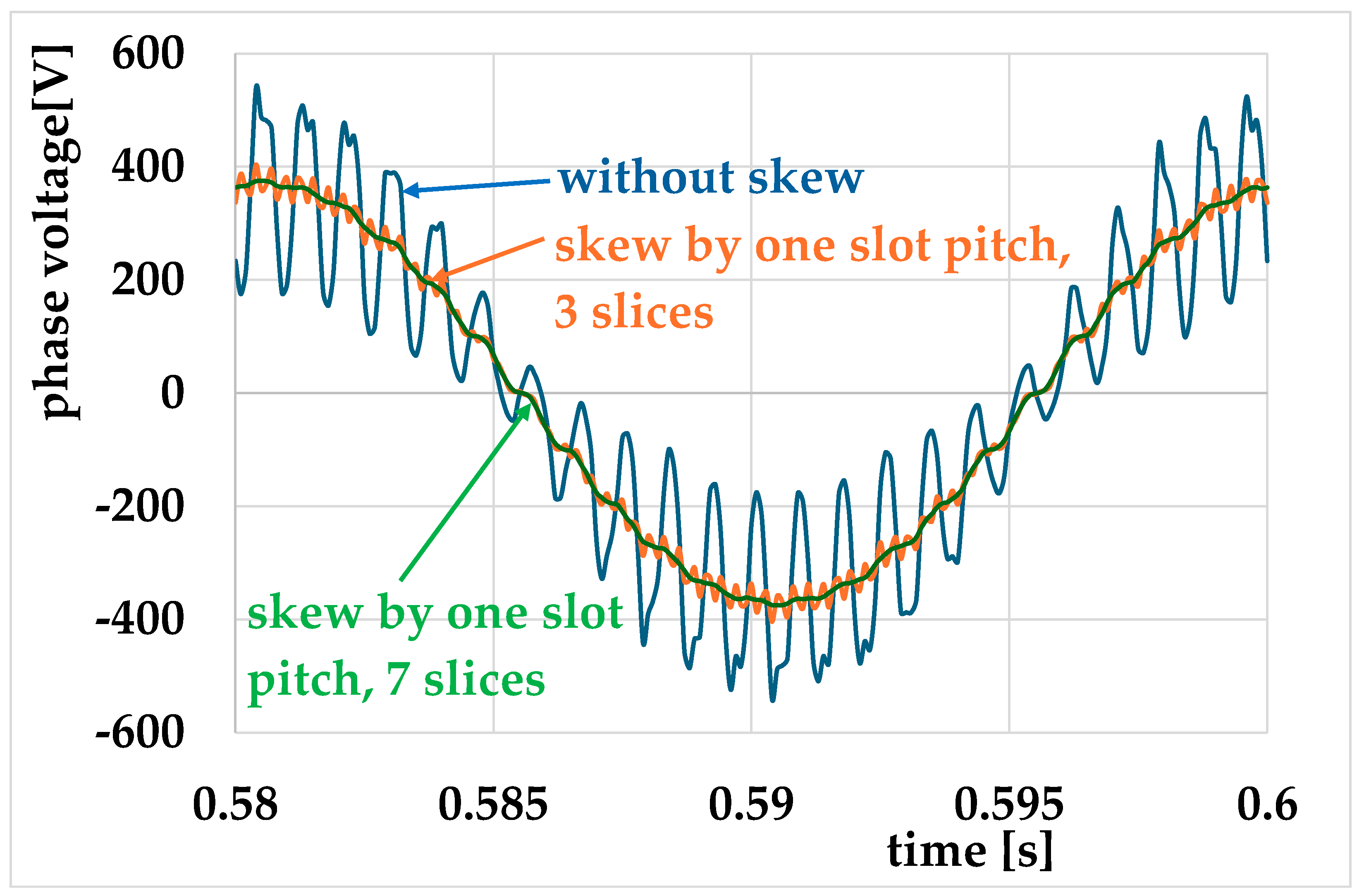
The analysis of phenomena in the synchronous machine was simulated using the RM module of the commercial software OPERA 2D with the transient eddy current solver. An important characteristic of the machines under study is the skewness of the stator slots. Applying the skew significantly improves the voltage shape due to the interaction of the stator and rotor slots. In our two-dimensional analysis, taking the skew into account requires the use of a multi-slice model. Figure 1 shows the effect of the skew on the generator voltage shape.
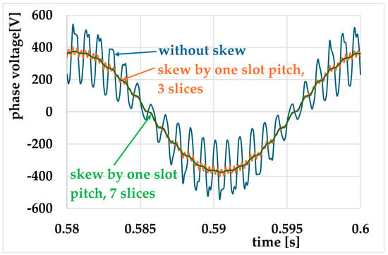
Figure 1.
The effect of the skew on the generator voltage shape.
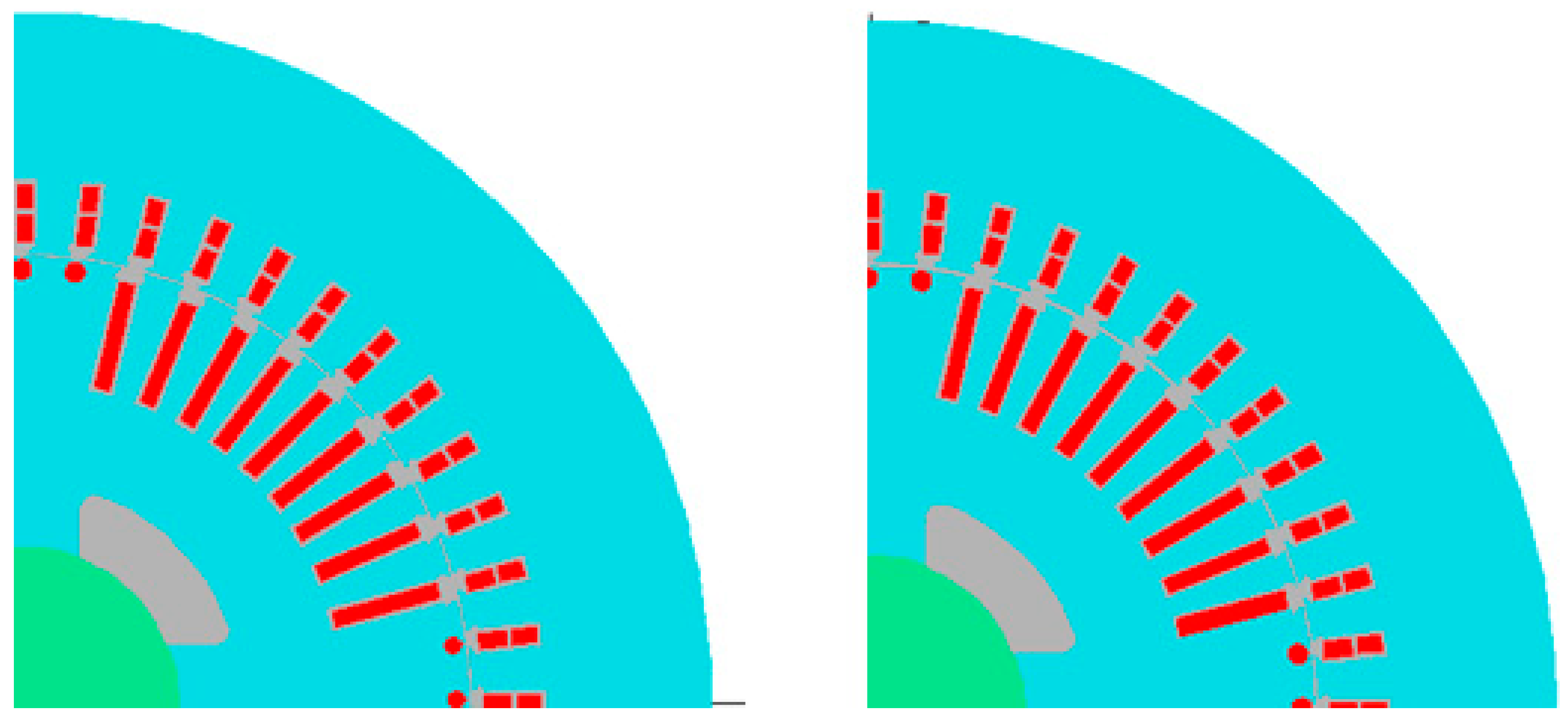
As can be seen, the skew significantly impacts the shape of the phase voltage. The specificity of the applied solution is the use of the skew of the stator slots and not the rotor, as in induction machines. Correctly including the skew in the two-dimensional model requires the use of a multi-slice model with seven layers. The need to use the multi-slice model increases the computation time. In machines with a cylindrical rotor, the rotor slots can be found with a constant slot pitch and with a groove pitch increasing towards the “wide tooth”. Calculations were performed for two such cases, shown in Figure 2, to examine the impact of such a structure on the magnetic field distribution.
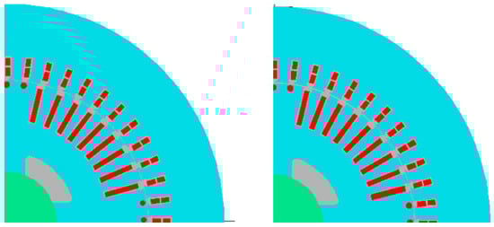
Figure 2.
Design with unevenly distributed field winding slots (left) and evenly distributed slots (right).
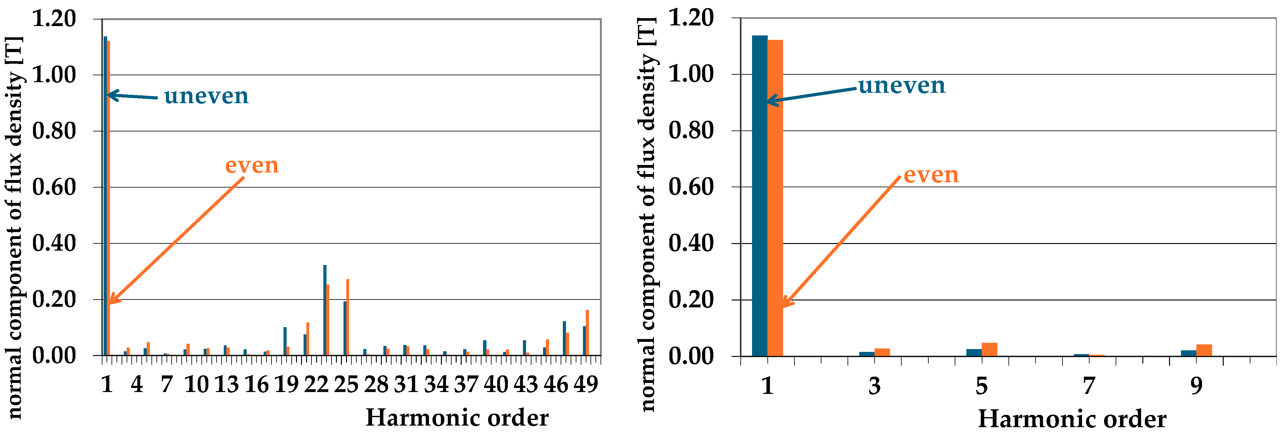
Figure 3 shows the harmonic decomposition for the normal induction component in the air gap with a range of up to the 50th harmonic in the left figure and an enlargement to the 10th harmonic in the right figure. As you can see, the uneven distribution of the rotor slots has a negligible impact on the value of the first harmonic of the field generating the fundamental voltage harmonic. As can be seen from the left figure, the effect on higher-order harmonics is ambiguous because some of them are reduced with the uneven distribution, and some are increased. From the point of view of the type of distribution taken into account in the analytical method, the most important aspect is its negligible impact on the first harmonic. This allows the non-uniform distribution not to be considered in the basic calculations of the analytical method.
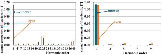
Figure 3.
Comparison of the harmonic distribution for the normal flux density component at air gap for structures with unevenly and evenly distributed rotor slots.
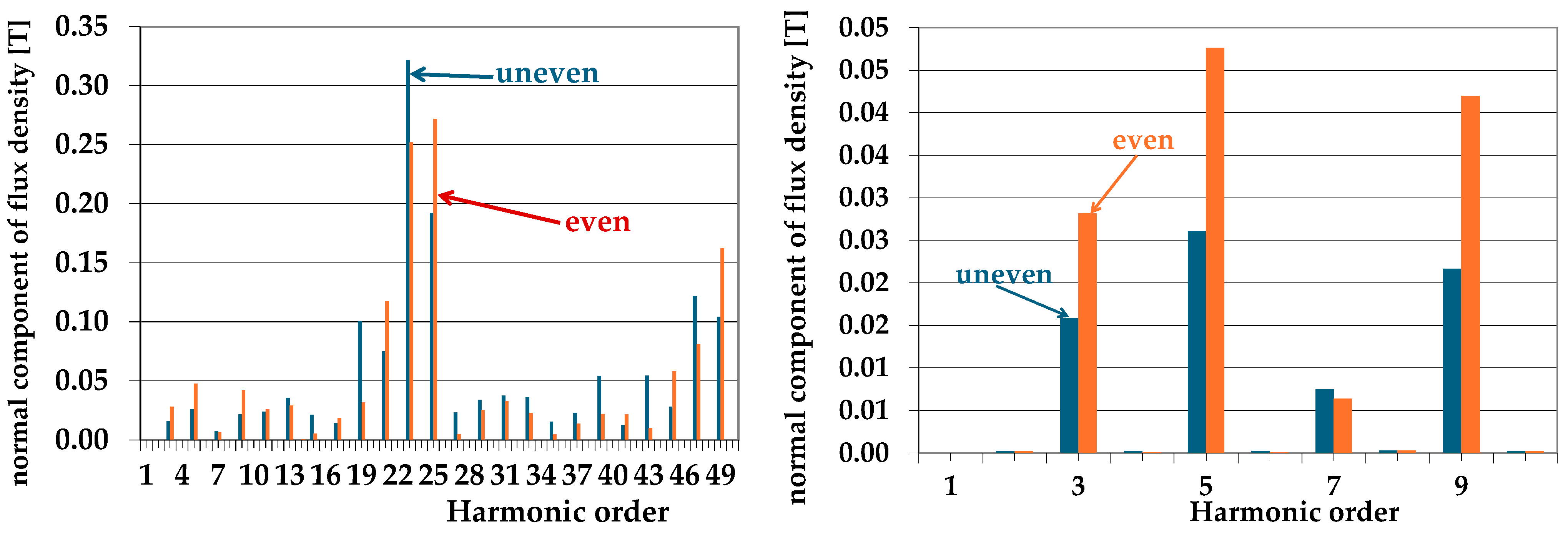
Figure 4 shows the distributions presented previously in Figure 3, but with the first harmonic omitted, which highlights the impact of non-uniformity on the magnitudes of higher-order harmonics. As you can see, the uneven distribution positively affects the magnitude of low-order harmonics and partially affects the magnitude of higher-order harmonics.

Figure 4.
Comparison of the harmonic distribution for the normal flux density component at air gap for structures with unevenly and evenly distributed rotor slots (omitting the 1st harmonic).
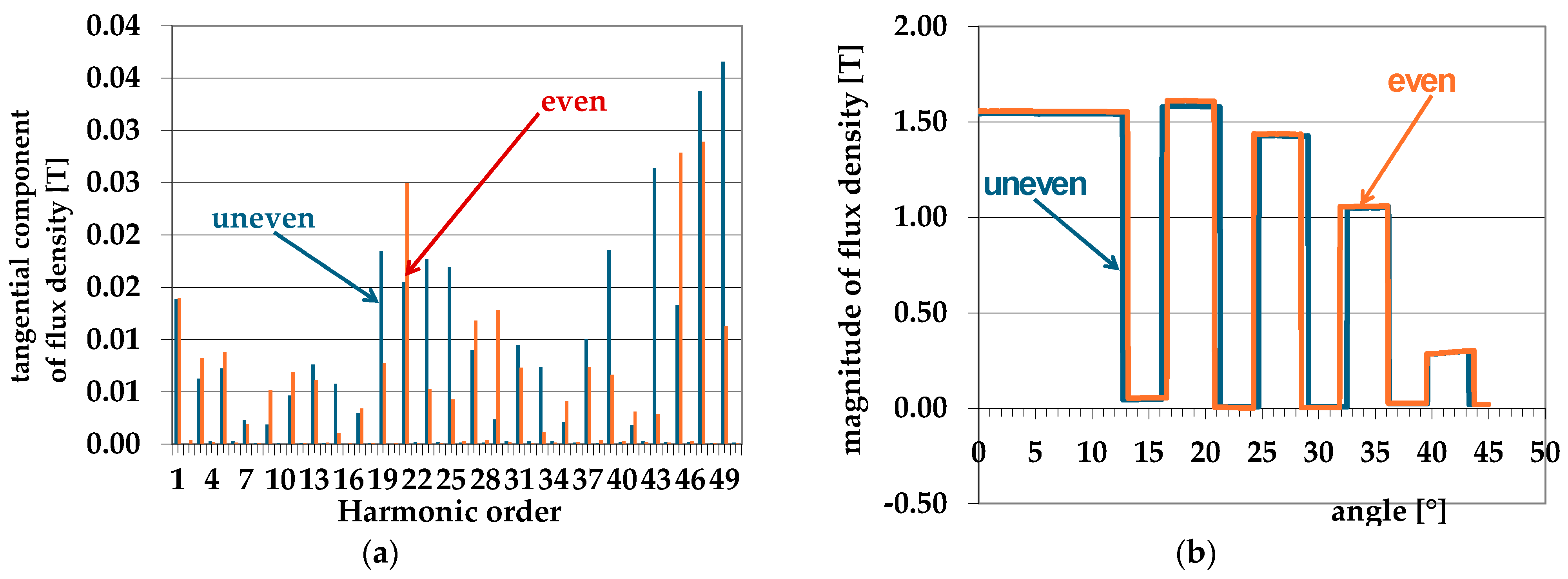
As can be seen from the presented distributions (Figure 4 and Figure 5), the uneven distribution of rotor slots has minor impact on the distribution of induction in the air gap. However, a slight positive effect on the content of higher-order harmonics in the air gap field curve can be noted for structures with an uneven distribution of rotor slots.
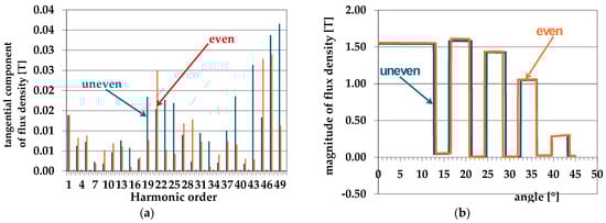
Figure 5.
Comparison of the decomposition into harmonics for the tangential component of flux density for structures with unevenly and evenly distributed rotor slots (a); comparison of the magnitude of flux density as a function of angle for structures with unevenly and evenly distributed rotor slots (b).
As stated in the introduction, the FEM is used to analyze synchronous machines mainly in terms of determining parameters [33,34,35,36,37,38]. As in the case of induction, permanent magnet, or reluctance machines, the use of the FEM to calculate losses is related to post-processing activities [29,55,56,57,58]. The main problem in these calculations is obtaining an approximation of losses in the core material for a wide range of induction values and frequencies (up to several kHz for high-order harmonics). In many articles, the concept of loss separation is divided into three components, hysteresis, classical, and excess losses, as proposed by Bertotti [59]. However, this approach creates additional problems in determining the approximation coefficients, especially for additional losses. For this reason, in the method proposed by the authors of [60], we use the classic assumption of Jordan [61], in which iron losses are separated into static hysteresis losses and dynamic eddy current losses as follows:
In [62], it can be seen that the coefficient of determination R2 for the linear approximation versus the frequency of losses divided by the frequency is greater than 0.95, which proves the obtained curves perfectly fit the linear distribution. Also, the relative mean square error value for the approximation with a linear function for individual induction values does not exceed 3%. The original approach of the authors according to these considerations was to introduce a corrected expression to calculate the loss in the core of the electric machine with the following form:
with four coefficients: kh, α, ke, and β.
To obtain an adequate level of accuracy, the frequency range, being the subject of the loss approximation, was divided into sub-ranges. The method proposed by the authors provides a better accuracy and is less complex than the multivariable polynomial response surface function fitting approach [29]. Additionally, the developed method takes into account the impact of sheet metal cutting, which is important for smaller machines [62].
The generators’ core losses were calculated using the method described in [63,64,65,66,67], which was initially used to estimate losses in induction motors.
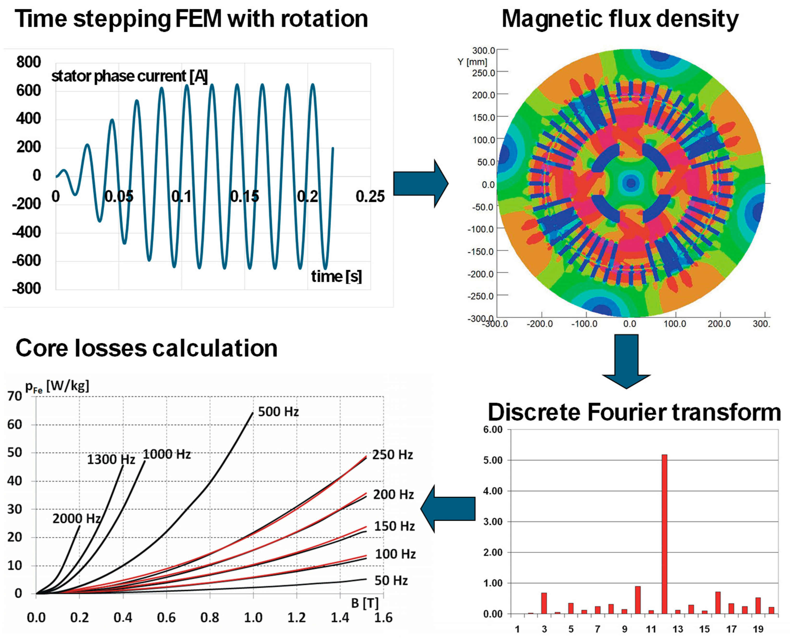
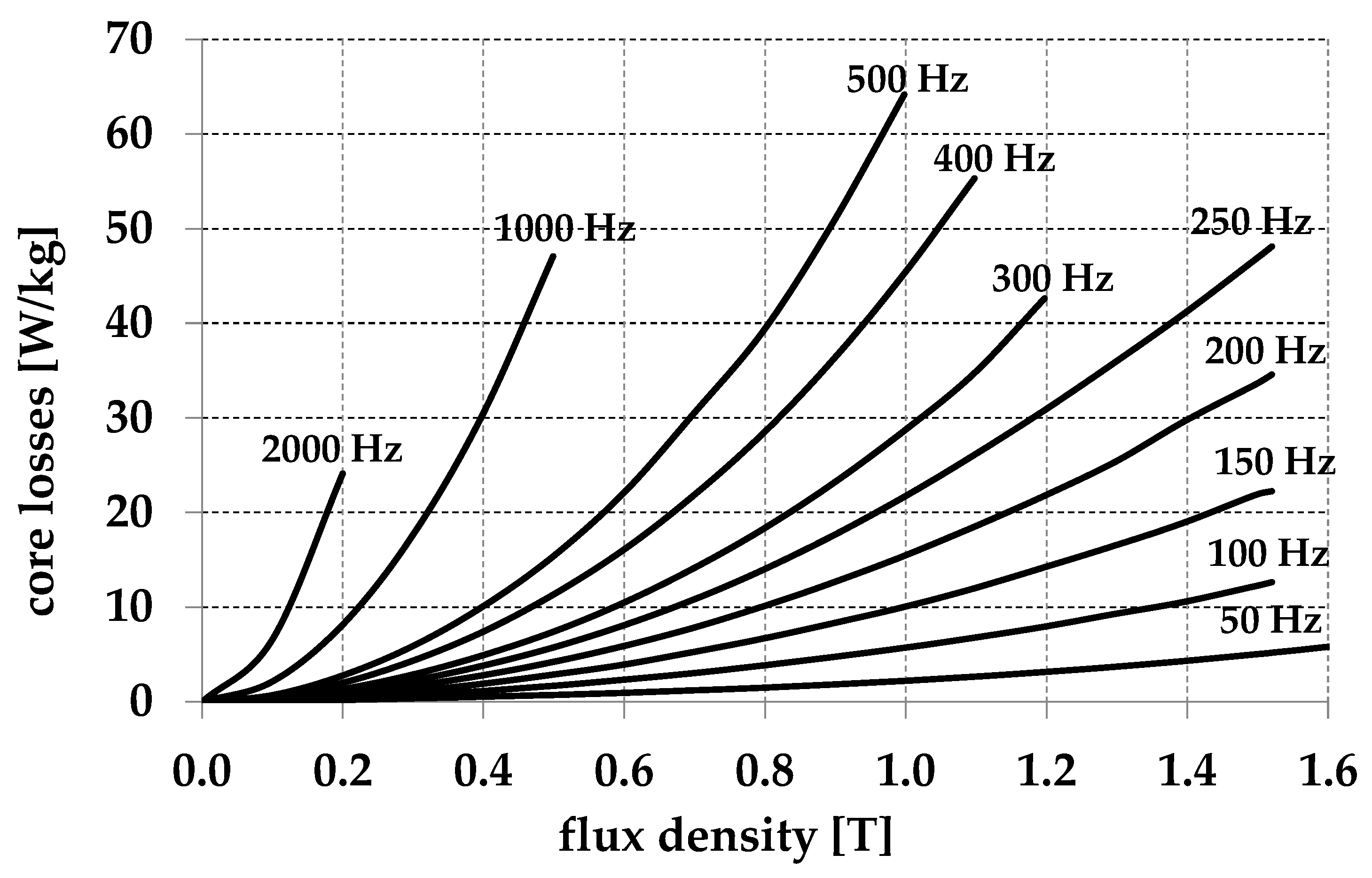
Figure 6 shows the procedure for calculating the losses in the generator core. When the model is turned on, an unsteady state occurs both in the idle and loaded states, and simulations are performed in the initial phase until the steady state is reached. After reaching the steady state, the values of the induction components are recorded in all elements of the core division mesh for a selected number of time moments for one period of voltage changes. To analyze phenomena in a wide frequency range, 400 samples per period were used. Adequate sample values require an appropriately dense division of the air gap so that the rotor displacement between two subsequent samples is many times greater than the size of the gap element. This results in the need to use a suitably dense division mesh. For machine A, the radius of the center of the air gap is 194.375 mm. Since the rotor makes half a revolution during the voltage period, there is a rotation of 1.53 mm between subsequent samples. To obtain an appropriate level of accuracy within the gap, elements with a pitch (the length of the longest side of the triangular element) equal to 0.5 mm were used. The recorded values of induction in each of the elements are then subjected to a discrete Fourier transform, which allows for the determination of the harmonics of induction in each element to be of the order of 200 (according to Schannon’s theorem). The power losses in each element can then be determined based on the amplitude of the induction harmonics. This requires measuring the loss of the core sheet over a wide range of induction values and frequencies. The loss characteristics for the M600-50A sheet measured on toroidal samples with a wide range of frequencies and induction values are presented in Figure 7.

Figure 6.
Diagram of the method for calculating losses in the machine core.

Figure 7.
The loss characteristics for the M600-50A sheet.
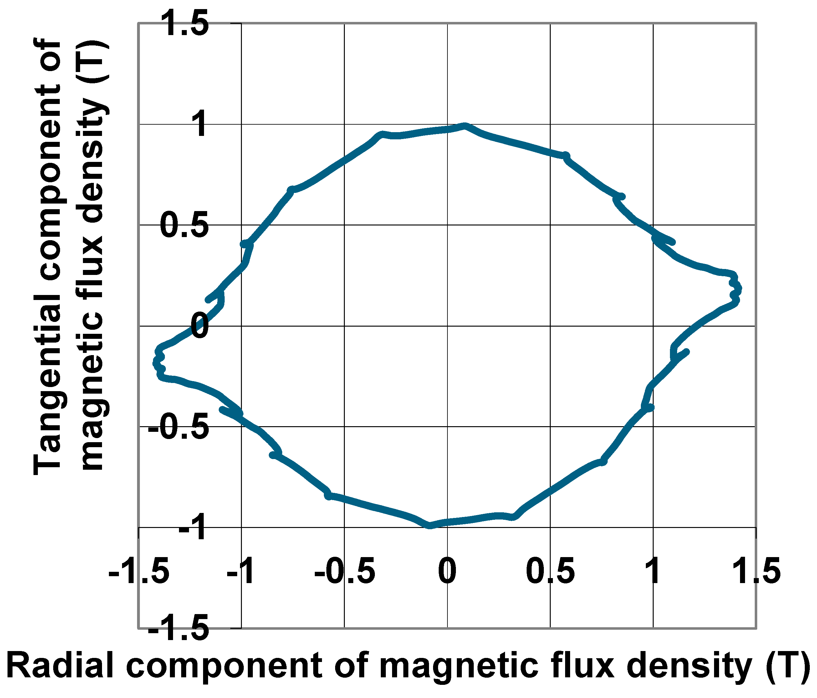
An additional problem that appears when calculating losses is the increase in losses related to the circularity of the field (rotational losses). In some regions of the machine, the field is not pulsating as it is in the measuring device, but the induction vector in time follows a shape similar to an ellipse. An example is the hodograph of the magnetic induction vector, which is shown in Figure 8, for a point located above the tooth in the area of the yoke.
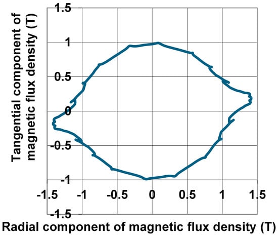
Figure 8.
Flux density vector loci.
The degree of rotation is expressed in terms of the axis ratio, which is defined as the ratio of the minor to major axes.
where Bmaj and Bmin are the peak flux density values along the major and minor axes of the field loop. The axis ratio distribution for the first harmonic is presented in Figure 9. Areas with a λ value close to unity are characterized by a high degree of rotation, so the field in these areas is closest to a circular shape. As can be seen from Figure 9, these are the areas of the yoke located above the stator teeth. The size of the area of the elliptical field depends on the proportions of the machine dimensions and increases with the increase in the external diameter of the stator.
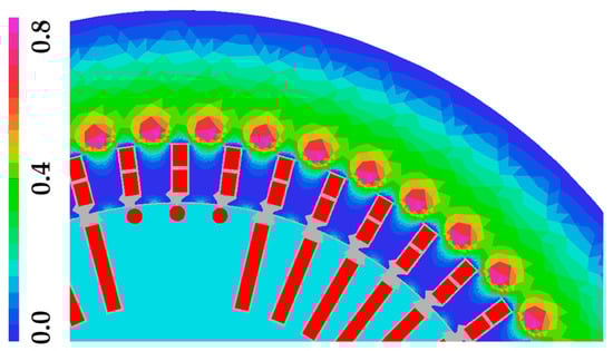
Figure 9.
The axis ratio distribution for the first harmonic for generator A.
The field’s rotation is not critical for the considered generators because only a small core volume is subjected to the rotational flux (less than 12 or so percent for the first harmonic). However, it should be remembered that for high-power generators, approximately 60–70% of the stator core volume is subjected to alternating flux and approximately 30–40% to rotating flux. The rotational losses were calculated as follows [68,69,70]:
where the Palt values are the measured alternating iron losses. The values of loss growth coefficient γ as a function of λ and Bmaj are shown in Figure 10 [68,69,70].
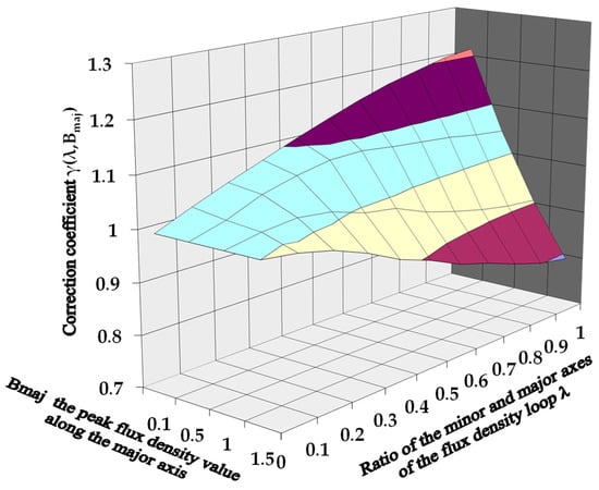
Figure 10.
Correction coefficient γ(λ,Bmaj).
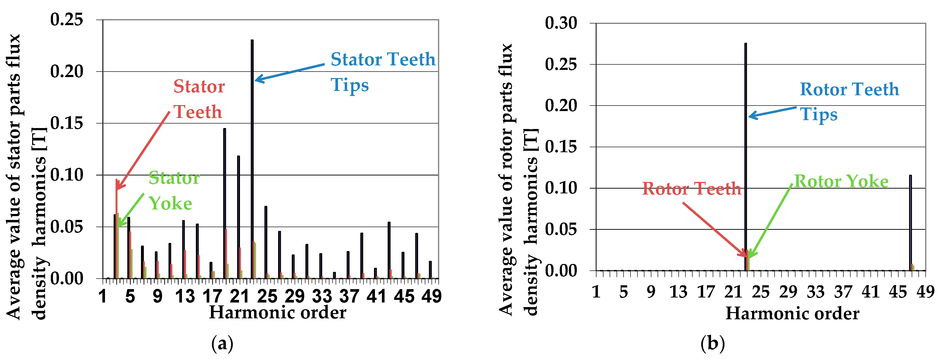
Figure 11 shows the average value of the stator part’s flux density spectrum calculated for generator A (a) and the average value of the rotor part’s flux density spectrum for generator A (b), both at no-load and omitting the first harmonic, which is dominant. As can be seen for the stator, we can observe two types of harmonics: low-order harmonics, the source of which is the change in the saturation of the rotor, especially the wide tooth; and high-order harmonics, the source of which is the slotting of the rotor. Although the entire circumference of the rotor is not slotted, there are slots in the wide-tooth area of the damping circuit, which function similarly to the slots of the excitation circuit.
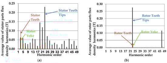
Figure 11.
The average value of the stator part’s flux density spectrum calculated for generator A (a); and the average value of rotor part’s flux density spectrum for generator A (b), both at no-load.
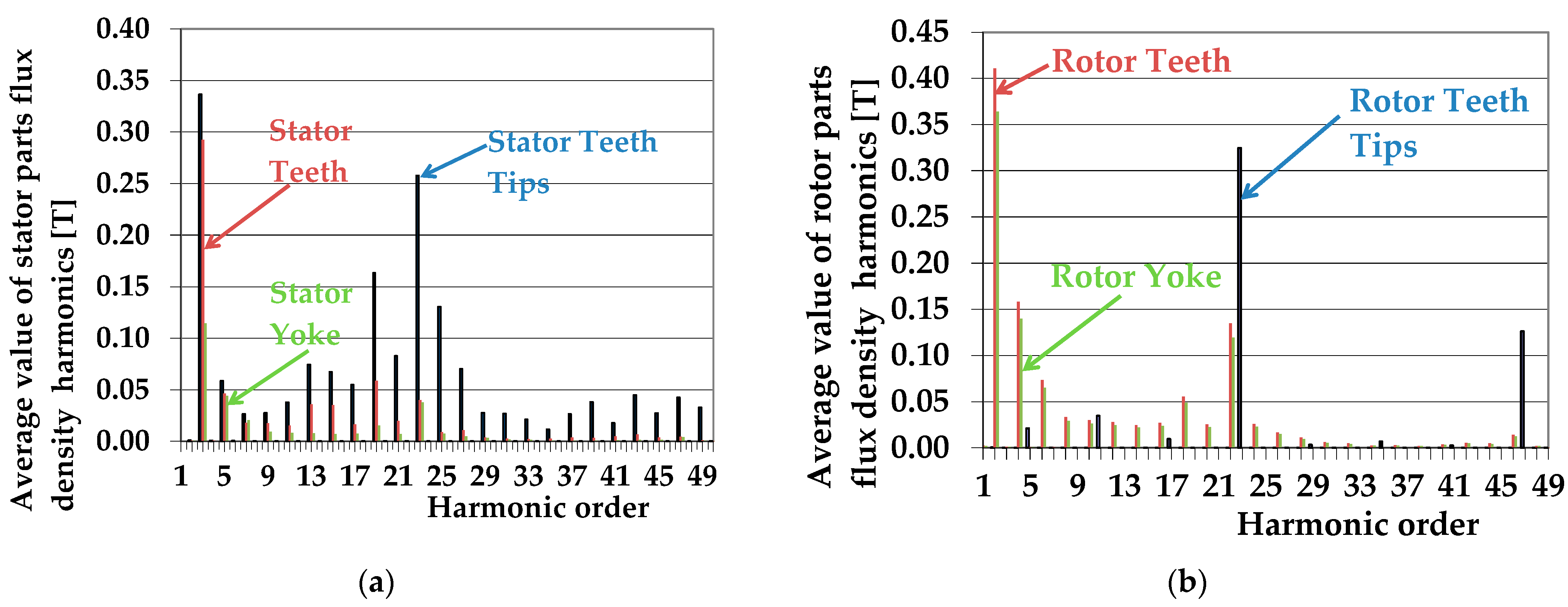
Figure 12 shows the average value of the flux density spectrum of the stator parts calculated for generator A (a) and the average value of the flux density spectrum of the rotor parts for generator A (b), both at the rated load, omitting the first harmonic. Compared to the no-load state, we can observe a significant increase in the induction for low-order harmonics and the appearance of such harmonics for the rotor. An increase in the induction of higher-order harmonics can also be observed due to the appearance of a significant leakage flux in the stator winding. Still, this increase is not as substantial as that observed for induction machines, in which both the rotor current and the stator current increase with the load.
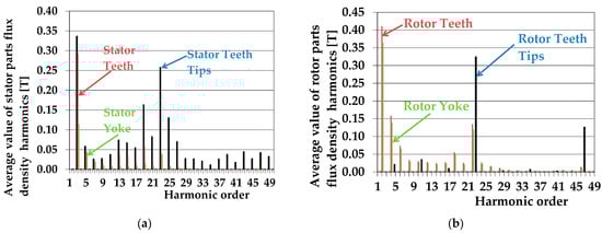
Figure 12.
The average value of the stator part’s flux density spectrum calculated for generator A (a); and the average value of rotor part’s flux density spectrum for generator A (b), both at rated load.
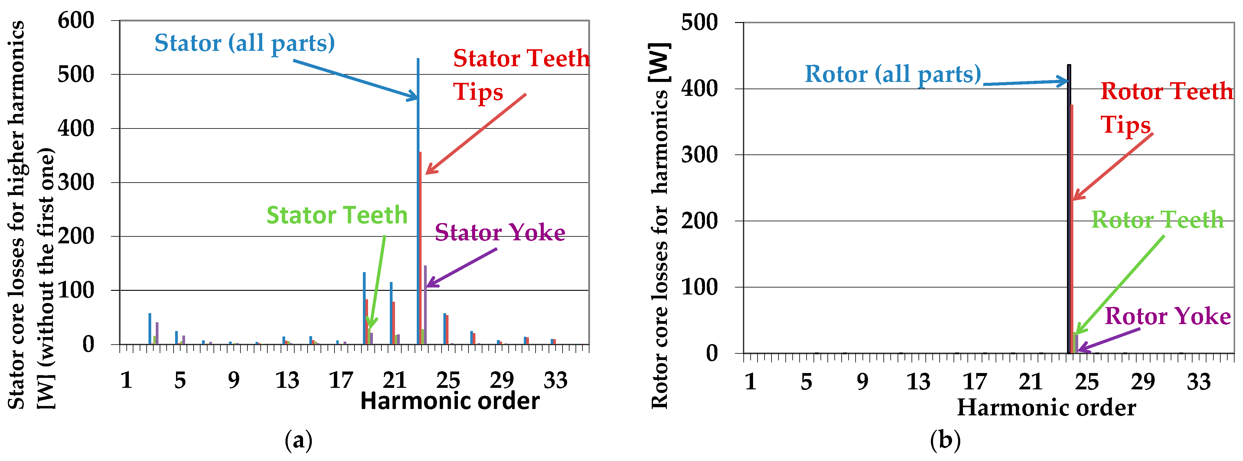
Figure 13 shows the stator core loss spectrum calculated for generator A (a) and the rotor core loss spectrum for generator A (b), both at no-load, omitting the first harmonic, which is dominant. Since eddy current losses increase with the square of the frequency, high-order harmonics, despite having smaller induction amplitudes, produce more significant losses than low-order harmonics. For this reason, slotting harmonics are the dominant source of losses, similar to induction machines.
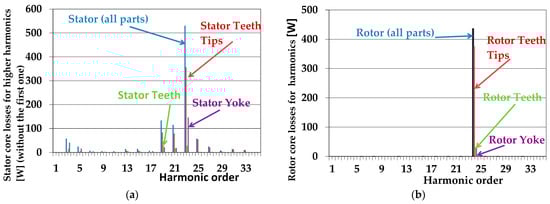
Figure 13.
The stator core loss spectrum calculated for generator A (a); and the rotor core loss spectrum for generator A (b), both at no-load.
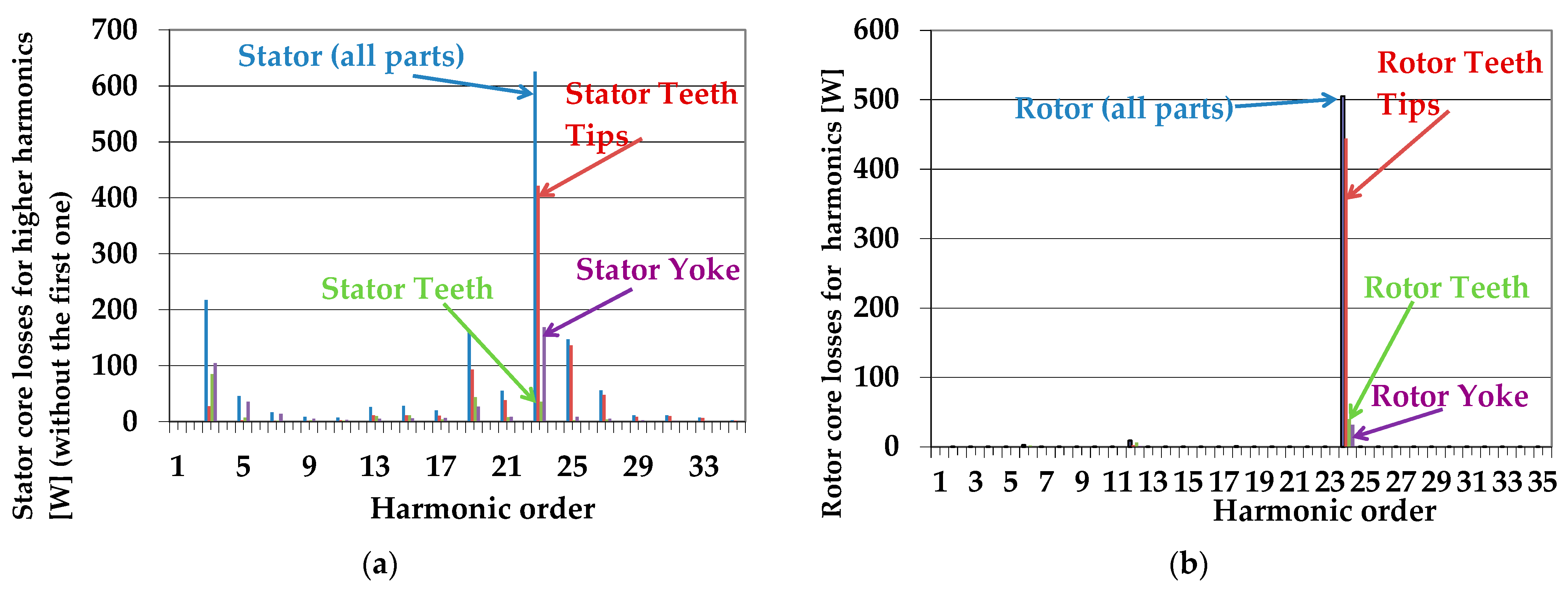
The situation of losses for the load condition is similar (Figure 14). We observe increased losses, but they are not as significant as those for induction machines.

Figure 14.
The stator core loss spectrum calculated for generator A (a); and the rotor core loss spectrum for generator A (b), both at rated load.
One can notice a significant contribution of slotting harmonics to the total losses. Thus, the losses in the stator and rotor are dominated by the losses in the tooth tips.
Figure 15, Figure 16, Figure 17 and Figure 18 show the distribution of calculated magnitudes of the flux density harmonics for generator A at rated load.

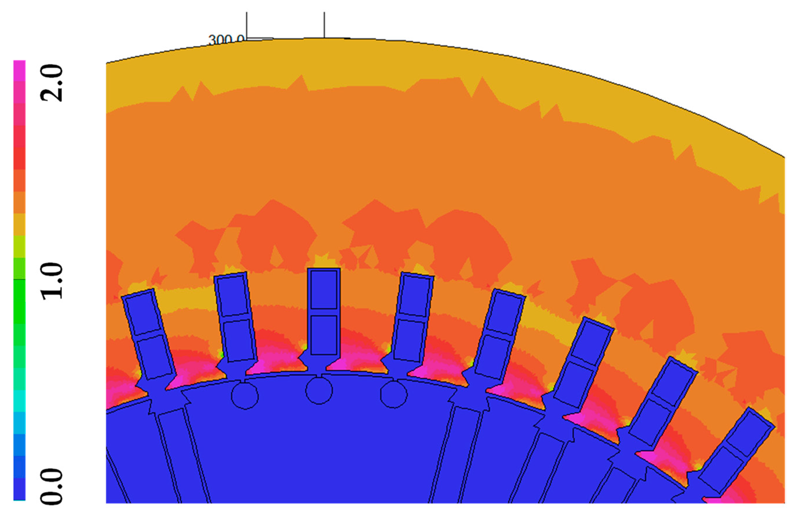
Figure 15.
The magnitude of the first harmonic of magnetic flux density for generator A.
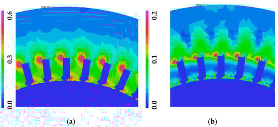
Figure 16.
Magnitude of the third harmonic (a) and fifth harmonic (b) of magnetic flux density for generator A.

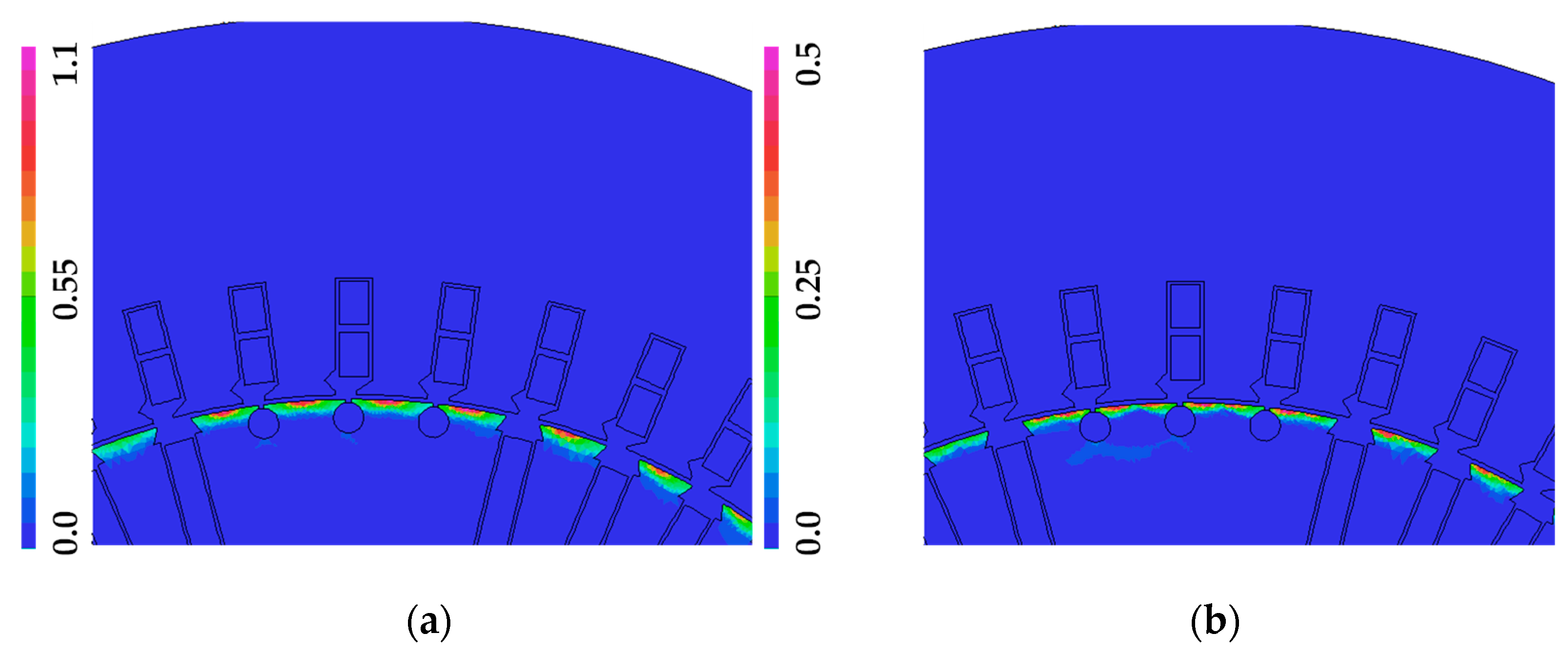
Figure 17.
Magnitude of the 24th harmonic (a) and 48th harmonic (b) of magnetic flux density for generator A.
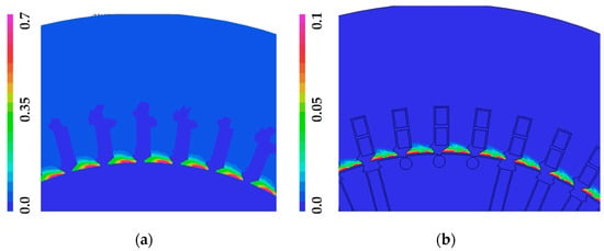
Figure 18.
Magnitude of the 23rd harmonic (a) and 49th harmonic (b) of magnetic flux density for generator A.
Figure 15 shows the amplitude distribution of the first harmonic of induction. For the tested machine, this distribution is quite uniform, except for the increase in induction in the tooth-narrowing area caused by the cutout for the stator winding wedge. The uniformity of the distribution indicates an optimal design of the magnetic system, which is used evenly.
Low-order harmonics are caused, among other things, by the influence of changes in the saturation of the magnetic circuit. Higher-order harmonics are harmonics resulting from the slotting of the stator and rotor.
Figure 16 shows the distribution of the amplitude of the low-order harmonics of magnetic induction: the third and fifth. As you can see, the amplitude of the third harmonic, in particular, is significant, but its distribution is uneven, reducing the value of losses generated by this harmonic.
Higher-order harmonics mainly affect the heads of the stator teeth and the rotor surface. The higher the harmonic order, the shallower its penetration into the core sheet. Even though the occurrence of these harmonics is practically limited to the core area near the air gap, the losses generated by higher-order harmonics reach significant values. This is due to the almost quadratic dependence of losses on the harmonic order for high-order harmonics.
Analogous calculations, as for generator A, were performed for generator B. A summary of the calculation results for generator A and generator B is presented in Section 3.
As can be seen from the presented analysis, similarly to induction machines, we also observe an increase in core losses, especially in the rotor, when the machine is loaded compared to those in the idling state of synchronous machines. This phenomenon has already been noted in the works of [71,72,73,74]. In the case of high-power generators, the influence of the key bar [75] and mechanical stresses on losses [76] should also be taken into account. The phenomenon of loss generation in a single metal sheet was investigated using a three-dimensional model in [77]. Generally, numerical methods are used nowadays in papers to study losses; only the work of [78] proposes using analytical methods.
The presented method allows for precisely determining core losses at the machine design stage. Unfortunately, its ability to reduce losses from higher-order harmonics is limited. Magnetic wedges can be used, similar to high-power induction motors. However, the magnetic properties of the magnetic wedges currently available on the market are far from satisfactory. Another problem is the mechanical strength of the wedges, which are subjected to significant magnetic forces. The use of wedges also increases the leakage flux.
4. Calculation of Losses in the Core of a Synchronous Machine with a Cylindrical Rotor Using the Analytical Method
For these machines, the core losses were also calculated using the analytical method for the same machine operating conditions as those for the calculations made using the field-circuit model. The analytical model was based on the equivalent circuit of a synchronous machine. In this model, a uniform, average rotor slot pitch was assumed, and on this basis, the number of rotor slot pitches Qr2 was determined while checking the following condition:
The basic losses in the stator teeth were calculated for the fundamental harmonic of the field, in which the tooth was divided along with the height into six layers as the sum of the losses in each layer for the actual value of the induction occurring in that layer, while the basic losses in the stator yoke were calculated for the mean value of the induction in the yoke.
The higher-order harmonics of the air gap’s magnetic fields were included in the analytical calculation of the additional core losses. In [67], additional surface losses in the stator and rotor teeth (), caused by the stator (rotor) flux density Br(s),νr(s) harmonics of rank νs(r), were calculated using the method from [65], based on the measured specific core losses wFe for all individual harmonics of the stator and the rotor fields (in the frequency range from 10 to 2000 Hz). In the calculations of surface and pulsation losses in the stator core, the rotor slot harmonics of the following order were obtained:
Meanwhile, when calculating the surface losses in the rotor core, both the tooth and stator excitation harmonics were taken into account with the following order:
In this method, concerning the formulas provided in [65], the dependence specifying the depth of field penetration into the heads of the stator and rotor teeth (λs(r),νr(s) (m)) was modified according to [67] as follows:
where wFe (W/kg)—the specific iron losses for fνr(s) and Br(s),νr(s), ρFe (kg/m3)—the mass density of the core material, Dsi(re) (m)—the internal (external) diameter of the stator (rotor) core, Ls(r) (m)—the length of the stator (rotor) core, kFe—the packing factor of the core, ts(r) (m)—the stator (rotor) slot pitch, bs(r) (m)—the width of the stator (rotor) slot opening, Qs—the number of stator slots, Qr2—the number of rotor slot pitches, fs (Hz)—the frequency of the first harmonic of the stator field, and p—the number of pole pairs.
The total additional surface losses in the stator or rotor teeth were calculated using the following formula [67]:
Additional pulsation losses in the stator teeth caused by the harmonic rotor fields were calculated using the formula given in [65].
The total core losses were calculated as the sum of basic losses, additional surface and pulsation losses in the stator core, and additional surface losses in the rotor core.
The results of calculating the individual components of the core losses and total core losses made using the field-circuit model and obtained from the analytical formulas considering the higher-order harmonics generated in the machines are given in Table 2 (for generator A) and Table 3 (for generator B). This shows a comparison of the calculation results for the rated load condition.
Table 2.
Calculated core losses for generator A at the rated load.
Table 3.
Calculated core losses for generator B at the rated load.
The total core losses measured during the no-load test for generator A were 4700 kW and for generator B were 1850 kW. The slightly higher calculated value of these losses under rated load conditions is related to increased losses in the machine core.
As shown in Table 2 and Table 3, the discrepancies in the total core losses calculated using the analytical and field-circuit methods do not exceed 3%. Concerning the measurement results, they do not exceed 10%. The slightly higher calculated values of core losses result from the fact that the calculation results from the rated load conditions, in which the basic losses may be slightly lower than those in the no-load condition, but the additional losses are higher, as a result of which the total losses at load are slightly higher than the losses in the no-load condition determined from the no-load test.
The calculations also considered additional losses caused by the leakage flux around the stator’s end–winding connections and the rotor’s field winding. These losses were calculated using the following formulas:
where Ns—the number of series turns of the stator winding, Nr1—the number of turns of the excitation winding per pole, Isf—the current in the phase winding of the stator, and If—the current in the excitation winding.
5. Determination of Parameters of the Equivalent Scheme of a Synchronous Machine with a Cylindrical Rotor
The experimental methods for determining the parameters of a synchronous machine are described in the IEC standard [79,80]. Correctly determining characteristic parameters, mainly reactance, for testing static states determines the accuracy of using equivalent machine diagrams to describe electrical characteristics. Both in the case of analytical models and FEM models, the problem is to determine the saturation state of the machine corresponding to the conditions occurring at the rated load. The next issue is selecting the method for determining the direct and quadrature reactance based on the numerical model. The work of [81] presents the determination of standard parameters through FE simulations of a three-phase short-circuit test, a field decrement test, a slip test, and an applied voltage test. The parameters obtained by these methods were then verified to operate a generator connected to an infinite network bus [82].
The time-stepping FEM is also used to determine the parameters when steady-state, transient, and sub-transient parameters are obtained by the multiple-step identification method [83] as well as a magnetostatic analysis [84]. In [85,86], the use of the standstill frequency response method was presented. The authors of [87] present the application of the time-domain chirp signal excitation to obtain the dq axis parameters of a synchronous machine model. The authors of [88] use the frozen permeability method in a two-dimensional finite element analysis to consider saturation and skin effects for determining the inductances. Similarly, in [89], a combination of the permeability freezing method and the standstill frequency response method was presented. Other methods used include load rejection (LR), the sudden short-circuit [90], and voltage step changes connected with the use of artificial neural networks [91]. The works of [92,93] emphasize that saturation representation is critical in the correct modeling of synchronous machines for high-power machines. However, for lower-power machines such as those considered in the article, especially for generators powered by diesel engines, the problem of determining the parameters is significant for simulating the operation of a microgrid with diesel generator sets [94].
As can be seen from the presented literature review, there is no quick method for determining the parameters of a synchronous machine using the FEM that takes into account the actual saturation state. In search of an appropriate method, the authors looked for methods to determine the parameters of synchronous machines with permanent magnets [95,96,97,98,99,100,101,102].
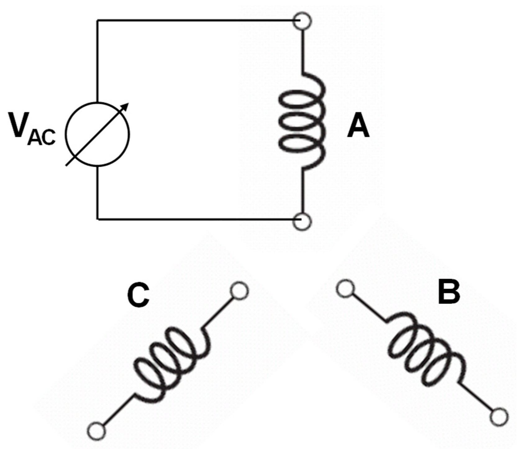
To determine the reactance of the machine for a given rotor position, one or more stator windings are powered from a sinusoidal voltage source (Figure 19).
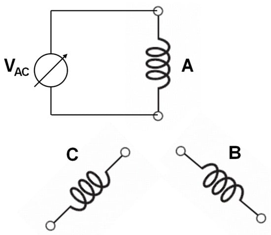
Figure 19.
The power supply scheme used for the inductance measurement of the machine.
Since the machine’s rotor is stationary in this simulation, the simulation requires both the excitation and damping circuits to be opened.
The simulated reactance for the tested machines, due to the design of the rotor, changes slightly when changing the rotor position, which is utterly different from the situation in salient pole machines. The reactance, however, is significantly dependent on the saturation state of the magnetic circuit.
Simulations were performed for machine B.
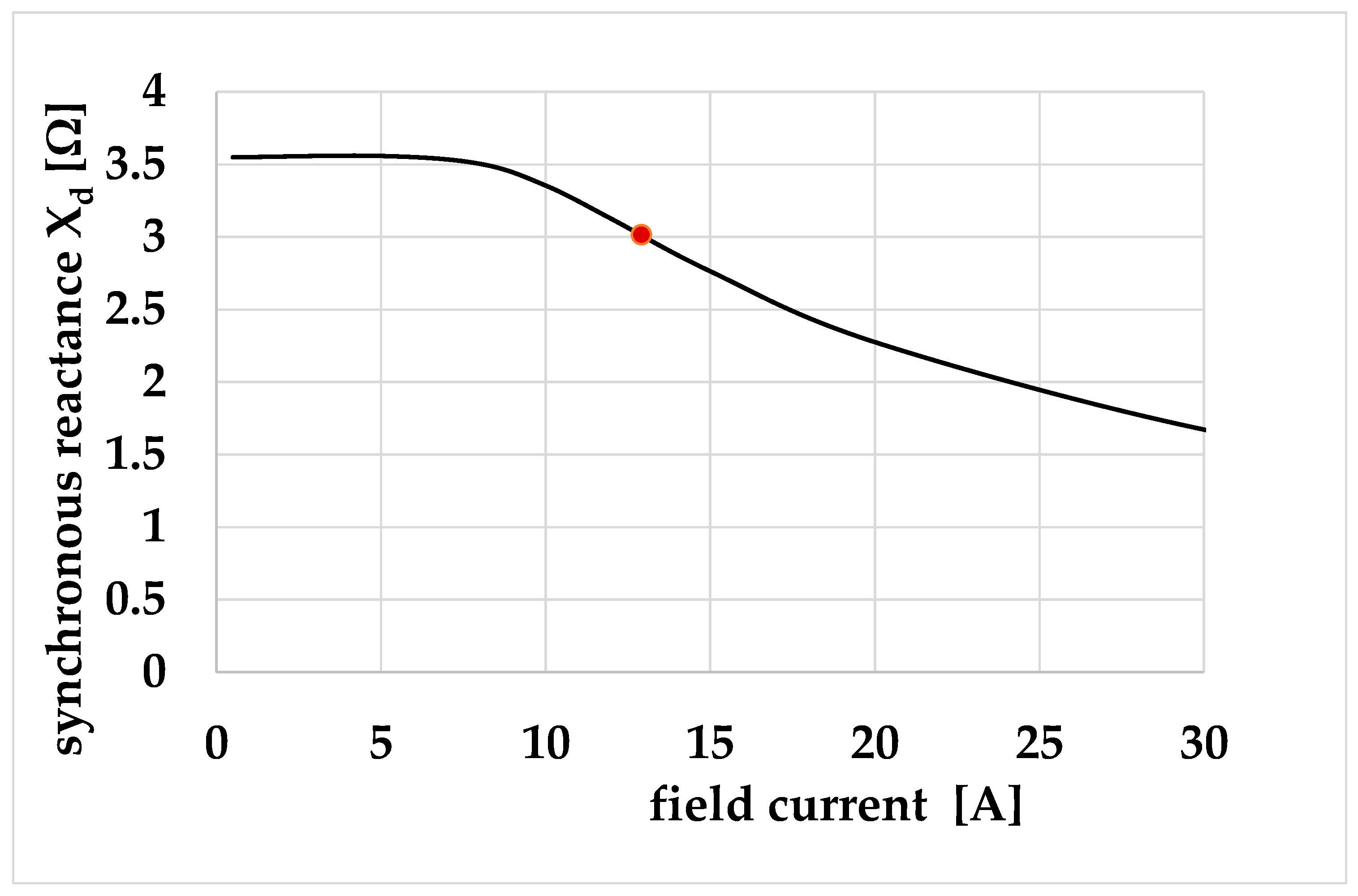
Figure 20 shows the longitudinal reactance relationship for generator B, determined based on the classical method using the measured characteristics of the no-load voltage versus the field current and the short-circuit test. The synchronous reactance determined for the rated field current for the rated voltage at no-load is 3.016 Ω.
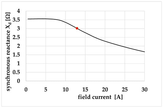
Figure 20.
The synchronous reactance determined based on the classical method using the measured characteristics of the no-load voltage versus field current and the short-circuit test. The red dot marks the reactance determined for the field current corresponding to the rated voltage for no-load operation.
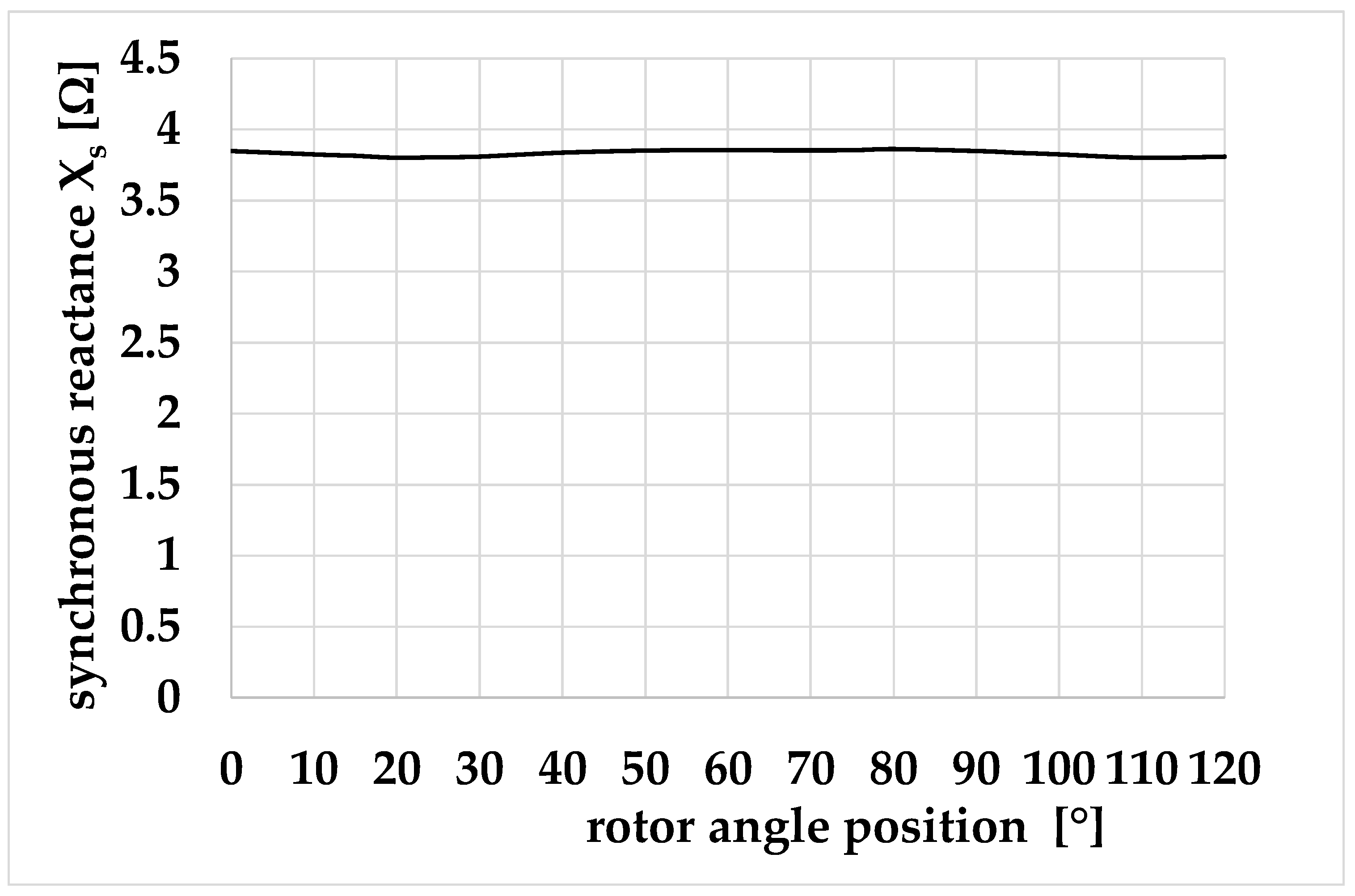
Figure 21 shows the change in the reactance of generator B as a function of the rotor position angle for a phase winding supply voltage of 100 V. As you can see, the variability in the reactance as a function of the rotor position is minimal and does not exceed 1.5%. Figure 22 and Figure 23 showA the reactance’s dependence on the machine’s saturation state. The calculations were performed for the rotor position corresponding to the situation in which the stator flux is in the direction of the rotor d-axis.

Figure 21.
The change in the reactance of generator B as a function of the rotor position angle for a phase winding supply voltage of 100 V.
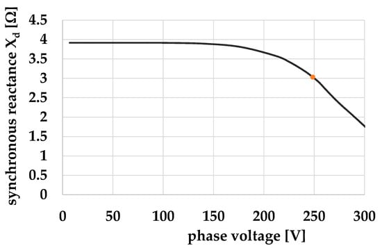
Figure 22.
The synchronous reactance of generator B as a function of the voltage supplying one phase winding of the machine for the rotor position angle corresponds to the situation in which the stator flux is in the direction of the rotor d-axis.
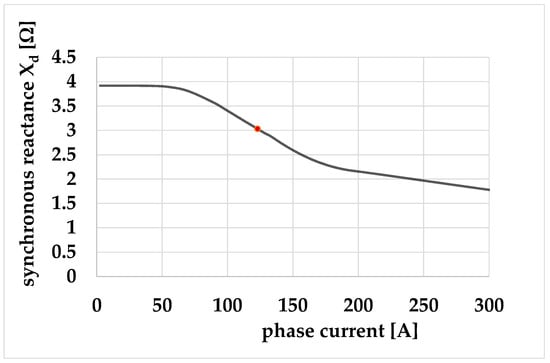
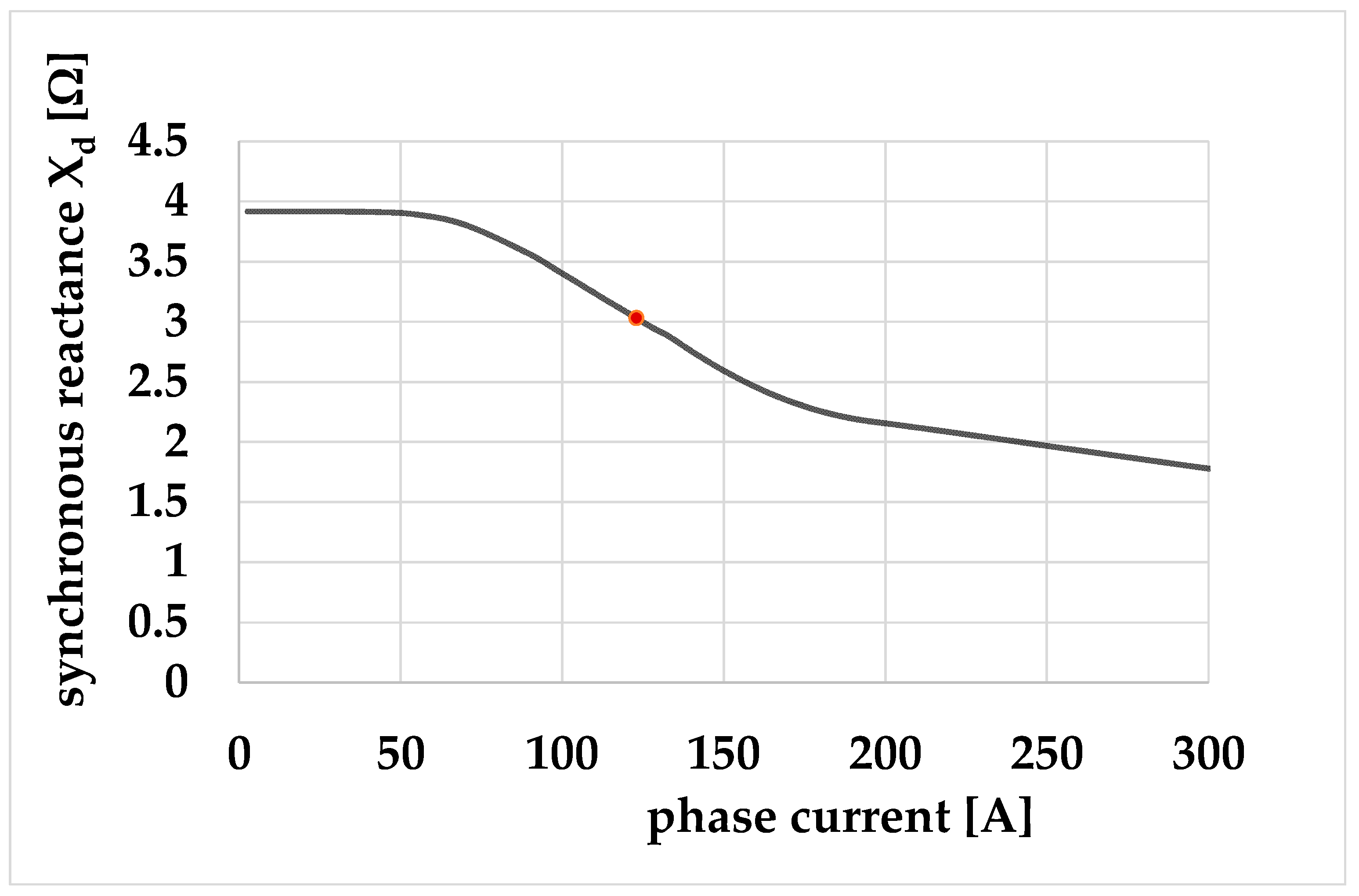
Figure 23.
The synchronous reactance of generator B as a function of the current in one phase winding of the machine for the rotor position angle corresponds to the situation in which the stator flux is in the direction of the rotor d-axis.
As you can see, the variability in the reactance with the change in saturation of the magnetic circuit is significant. For this reason, we need a criterion for selecting the saturation state for which we consider the value of the simulated reactance to be adequate. For this purpose, the value of the first harmonic of the normal component of induction in the air gap for the rated load (determined based on the FEM simulation) was 0.8 T. For the simulation of a single-phase power supply, the power supply condition for which this value is identical was determined. Then, the reactance was determined for this value. It is 3.031 Ω. The drawings show the corresponding reactance values as colored dots. As you can see, the obtained reactance values are similar. However, the problem of correctly determining the synchronous reactance based on the field solution so that it is adequate for analytical simulations requires further consideration. The parameter values of the equivalent machine diagram were also determined based on analytical calculations. The leakage reactance of the stator winding Xs, synchronous reactance Xd, and quadrature axis reactance Xq, being the sum of the leakage reactance and the armature reaction reactance in the direct axis and the quadrature axis in the unsaturated state and in the rated saturated state, for both generators, are presented in Table 4.
Table 4.
Synchronous reactance of the tested generators calculated analytically.
6. Determination of Steady-State Operating Characteristics of a Synchronous Machine with a Cylindrical Rotor
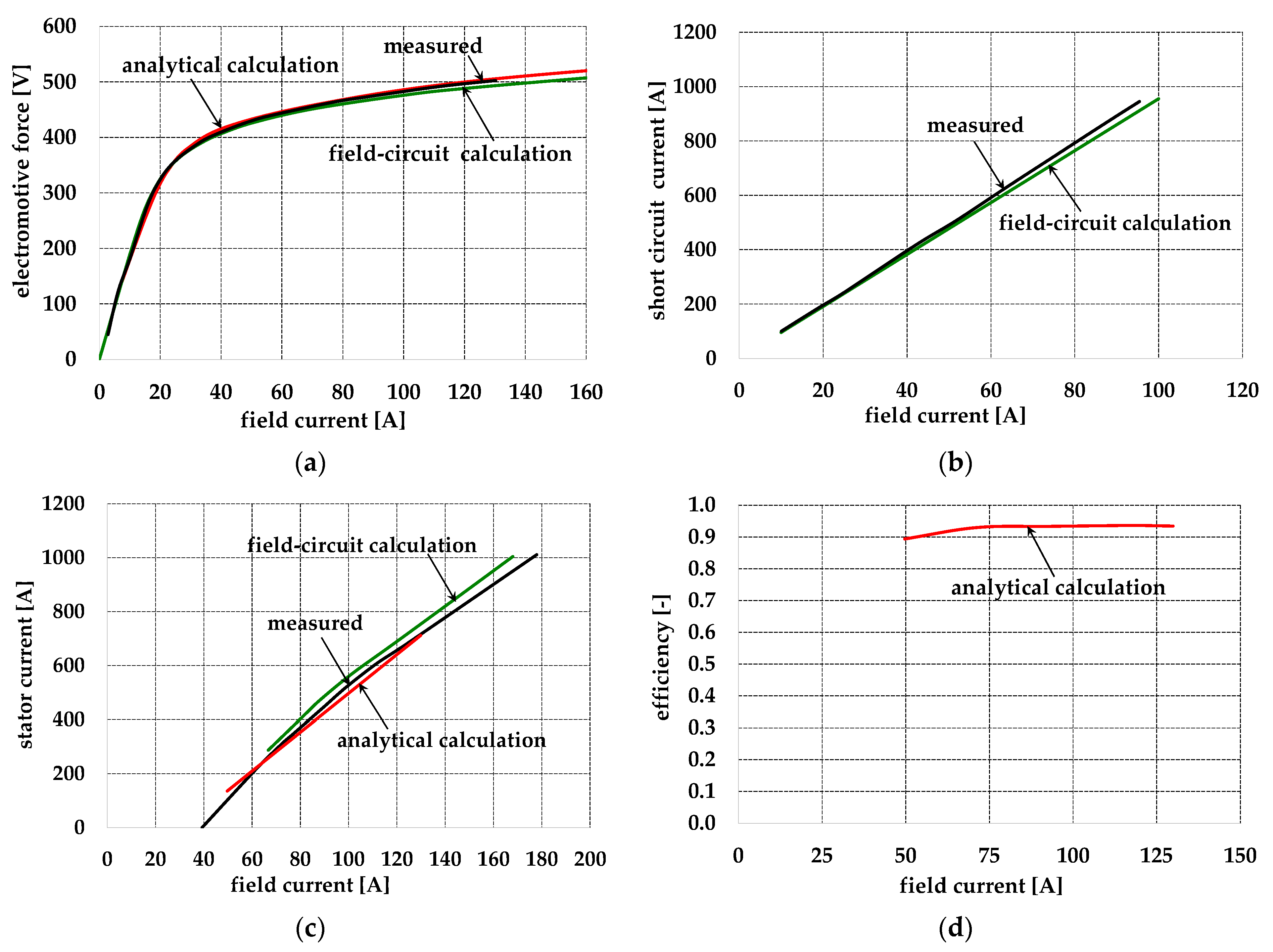
To assess the quality of the developed analytical and field-circuit models, selected operational characteristics were calculated using both models and compared with the measurement results. The measurements were performed in the manufacturer’s laboratory in accordance with IEC standards [79,80]. Figure 24 shows generator A’s main operational characteristics in terms of its no-load, short circuit, stator current versus field current at rated voltage, power factor, and efficiency curves.
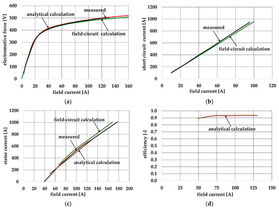
Figure 24.
No-load (a), short circuit (b), stator current versus field current at rated voltage and power factor (c), and efficiency (d) curves for generator A.
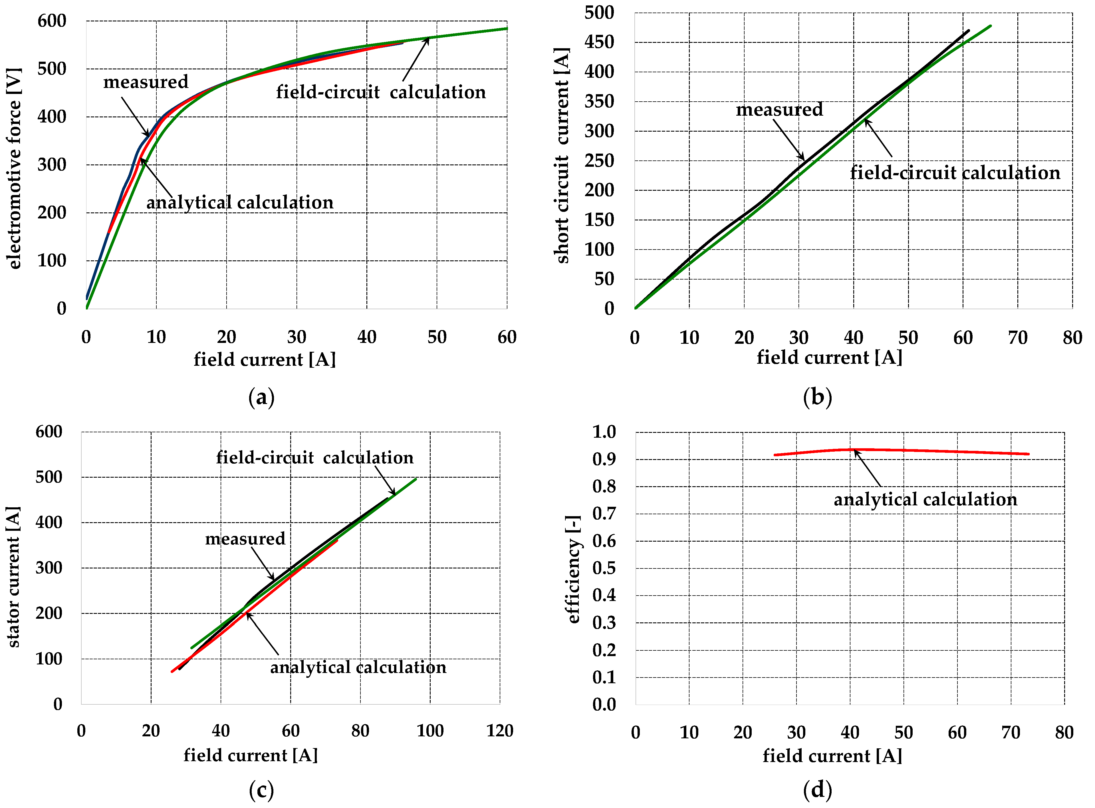
Analogous characteristics for generator B are shown in Figure 25.
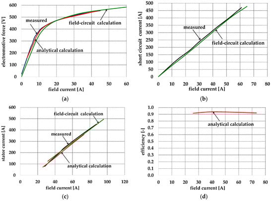
Figure 25.
No-load (a), short circuit (b), stator current versus field current at rated voltage and power factor (c), and efficiency (d) curves for generator B.
As shown in Figure 24 and Figure 25, the developed methods for calculating losses, parameters, and operational characteristics provide results that are consistent with the measurement results and have a sufficient level of accuracy. The efficiency measured at the rated excitation current for generator A is 93.7%, while the calculated efficiency is 93.6%. The efficiency measured at the rated excitation current for generator B is 91.9%, while the computed efficiency is 92.2%. These results indicate that the losses in both machines were correctly calculated.
7. Conclusions
Using numerical and analytical methods, this article analyzes phenomena in synchronous generators with a medium-power cylindrical rotor. In this field-circuit approach, the distribution of and variations in the machine magnetic flux density are calculated using the time-stepping FEM method. The discrete Fourier transform is then used to analyze each model element’s magnetic flux density waveforms, obtained from multiple time-step snapshots taken during the supply voltage period. The field’s rotational aspects are considered by introducing a correction for the first harmonic of the alternating losses. The core loss in each element is evaluated using a specific core loss expression in which the frequency-dependent parameters and flux are derived from a test performed on a sample of the laminated annular core. The results are compared with measurements, and a good agreement is observed between the two methods. However, the time-stepping FEM field-circuit method combined with skewing multi-slice method is quite time-consuming, so a fast analytical method is recommended for optimization.
The analytical method for calculating core losses and significant additional losses caused by higher-order harmonics of the magnetic field uses formulas analogous to those for induction motors, which take into account the dominant orders of stator conductivity harmonics, stator and rotor tooth harmonics, the actual (determined based on measurements and approximated using appropriate formulas) value of sheet-specific losses for the value of magnetic induction, and the frequency of each harmonic. Additional losses were also considered to be caused by the leakage flux in the front connections of the stator windings and the rotor winding. This made it possible to determine the efficiency of the generators with a sufficient level of accuracy compared to that of the measurement results without using any empirical coefficients. This method represents a significant novelty in assessing the efficiency of machines previously found in the literature.
Author Contributions
Conceptualization, K.K. and M.D.; methodology, K.K. and M.D.; software, K.K. and M.D.; validation, K.K. and M.D.; formal analysis, K.K. and M.D.; investigation, K.K. and M.D.; data curation, K.K. and M.D.; writing—original draft preparation, K.K. and M.D.; writing—review and editing, K.K. and M.D.; visualization, K.K. and M.D.; supervision, K.K. and M.D.; project administration, K.K. and M.D. All authors have read and agreed to the published version of the manuscript.
Funding
This research received no external funding.
Data Availability Statement
The data presented in this study are available in this article.
Conflicts of Interest
The authors declare no conflicts of interest.
References
- Nøland, J.K.; Nuzzo, S.; Tessarolo, A.; Alves, E.F. Excitation System Technologies for Wound-Field Synchronous Machines: Survey of Solutions and Evolving Trends. IEEE Access 2019, 7, 109699–109718. [Google Scholar] [CrossRef]
- Rahman, A.; Dutta, R.; Chu, G.; Xiao, D.; Thippiripati, V.K.; Rahman, M.F. Open-Winding Permanent Magnet Synchronous Generator for Renewable Energy—A Review. Energies 2023, 16, 5268. [Google Scholar] [CrossRef]
- Raouf, A.; Tawfiq, K.B.; Eldin, E.T.; Youssef, H.; El-Kholy, E.E. Wind Energy Conversion Systems Based on a Synchronous Generator: Comparative Review of Control Methods and Performance. Energies 2023, 16, 2147. [Google Scholar] [CrossRef]
- Bensalah, A.; Barakat, G.; Amara, Y. Electrical Generators for Large Wind Turbine: Trends and Challenges. Energies 2022, 15, 6700. [Google Scholar] [CrossRef]
- Knudsen, J.; Bendtsen, J.D.; Andersen, P.; Madsen, K.K.; Sterregaard, C.H. Supervisory Control Implementation on Diesel-Driven Generator Sets. IEEE Trans. Ind. Electron. 2018, 65, 9698–9705. [Google Scholar] [CrossRef]
- Pivetta, R.E.; Luiz Dal Forno, I.; Scherer, L.G.; de Camargo, R.F.; Grigoletto, F.B. Self-Excited Induction Generator Based Generation System Regulation Using Synchronous Generator as Reactive Power Compensator. In Proceedings of the 2022 14th Seminar on Power Electronics and Control (SEPOC), Santa Maria, Brazil, 12–15 November 2022; pp. 1–6. [Google Scholar] [CrossRef]
- Rozegnał, B.; Albrechtowicz, P.; Mamcarz, D.; Radwan-Pragłowska, N.; Cebula, A. The Short-Circuit Protections in Hybrid Systems with Low-Power Synchronous Generators. Energies 2021, 14, 160. [Google Scholar] [CrossRef]
- Kutt, F.; Michna, M.; Kostro, G.; Ronkowski, M. Modelling of steady state and transient performance of the synchronous generator considering harmonic distortions caused by non-uniform saturation of the pole shoe. Electr. Power Syst. Res. 2017, 143, 409–414. [Google Scholar] [CrossRef]
- Mon-Nzongo, D.L.; Ekemb, G.; Song-Manguelle, J.; Ipoum-Ngome, P.G.; Jin, T.; Doumbia, M.L. LCIs and PWM-VSIs for the Petroleum Industry: A Torque Oriented Evaluation for Torsional Analysis Purposes. IEEE Trans. Power Electron. 2019, 34, 8956–8970. [Google Scholar] [CrossRef]
- Graffeo, F.; Vaschetto, S.; Tenconi, A.; Cavagnino, A. No-Load Characteristic Computation for Wound Field Synchronous Propulsion Motors. In Proceedings of the 2023 IEEE International Conference on Electrical Systems for Aircraft, Railway, Ship Propulsion and Road Vehicles & International Transportation Electrification Conference (ESARS-ITEC), Venice, Italy, 29–31 March 2023; pp. 1–6. [Google Scholar] [CrossRef]
- Chen, J.; Liu, K.; Hu, W.; Qu, Y.; Geng, Y. A double -magnetic -bridge based brushless hybrid excitation synchronous machine for ship propulsion. In Proceedings of the 2022 IEEE 5th International Electrical and Energy Conference (CIEEC), Nangjing, China, 27–29 May 2022; pp. 3072–3077. [Google Scholar] [CrossRef]
- Lipo, T.A.; Du, Z.S. Synchronous motor drives-a forgotten option. In Proceedings of the 2015 Intl Aegean Conference on Electrical Machines & Power Electronics (ACEMP), 2015 Intl Conference on Optimization of Electrical & Electronic Equipment (OPTIM) & 2015 Intl Symposium on Advanced Electromechanical Motion Systems (ELECTROMOTION), Side, Turkey, 2–4 September 2015; pp. 1–5. [Google Scholar] [CrossRef]
- Hussain, A.; Baig, Z.; Toor, W.T.; Ali, U.; Idrees, M.; Shloul, T.A.; Ghadi, Y.Y.; Alkahtani, H.K. Wound Rotor Synchronous Motor as Promising Solution for Traction Applications. Electronics 2022, 11, 4116. [Google Scholar] [CrossRef]
- Graffeo, F.; Vaschetto, S.; Cossale, M.; Kerschbaumer, M.; Bortoni, E.C.; Cavagnino, A. Cylindrical Wound-Rotor Synchronous Machines for Traction Applications. In Proceedings of the 2020 International Conference on Electrical Machines (ICEM), Gothenburg, Sweden, 23–26 August 2020; pp. 1736–1742. [Google Scholar] [CrossRef]
- de Santiago, J.; Bernhoff, H.; Ekergård, B.; Eriksson, S.; Ferhatovic, S.; Waters, R.; Leijon, M. Electrical Motor Drivelines in Commercial All-Electric Vehicles: A Review. IEEE Trans. Veh. Technol. 2012, 61, 475–484. [Google Scholar] [CrossRef]
- Rehaoulia, H.; Henao, H.; Capolino, G.A. Modeling of synchronous machines with magnetic saturation. Electr. Power Syst. Res. 2007, 77, 652–659. [Google Scholar] [CrossRef]
- Hanic, Z.; Vrazic, M.; Maljkovic, Z. Steady-state synchronous machine model which incorporates saturation and cross-magnetization effects. In Proceedings of the 4th International Conference on Power Engineering, Energy and Electrical Drives, Istanbul, Turkey, 13–17 May 2013; pp. 1553–1557. [Google Scholar] [CrossRef]
- Mabhula, M.; Kamper, M.J. Model Parameter and Performance Calculation of Cylindrical Wound-Rotor Synchronous Motors. IEEE Trans. Energy Convers. 2021, 36, 412–420. [Google Scholar] [CrossRef]
- Mouni, E.; Tnani, S.; Champenois, G. Comparative study of three modelling methods of synchronous generator. In Proceedings of the IECON 2006—32nd Annual Conference on IEEE Industrial Electronics, Paris, France, 7–10 November 2006; pp. 1551–1556. [Google Scholar] [CrossRef]
- Kutt, F.; Michna, M.; Kostro, G. Multiple Reference Frame Theory in the Synchronous Generator Model Considering Harmonic Distortions Caused by Nonuniform Pole Shoe Saturation. IEEE Trans. Energy Convers. 2020, 35, 166–173. [Google Scholar] [CrossRef]
- Fallows, D.; Nuzzo, S.; Galea, M. Exciterless Wound-Field Medium-Power Synchronous Machines: Their History and Future. IEEE Ind. Electron. Mag. 2022, 16, 44–51. [Google Scholar] [CrossRef]
- Zhu, S.; Hu, Y.; Li, J.; Liu, C.; Wang, K. Magnetic Field Analysis and Operating Characteristics of a Brushless Electrical Excitation Synchronous Generator With DC Excitation. IEEE Trans. Magn. 2022, 58, 8106007. [Google Scholar] [CrossRef]
- Nuzzo, S.; Galea, M.; Gerada, C.; Brown, N. Analysis, Modeling, and Design Considerations for the Excitation Systems of Synchronous Generators. IEEE Trans. Ind. Electron. 2018, 65, 2996–3007. [Google Scholar] [CrossRef]
- Slemon, G.R. An equivalent circuit approach to analysis of synchronous machines with saliency and saturation. IEEE Trans. Energy Convers. 1990, 5, 538–545. [Google Scholar] [CrossRef]
- Laldin, O.; Sudhoff, S.D.; Pekarek, S. An Analytical Design Model for Wound Rotor Synchronous Machines. IEEE Trans. Energy Convers. 2015, 30, 1299–1309. [Google Scholar] [CrossRef]
- Zhang, Y.; Cramer, A.M. Unified Model Formulations for Synchronous Machine Model With Saturation and Arbitrary Rotor Network Representation. IEEE Trans. Energy Convers. 2016, 31, 1356–1365. [Google Scholar] [CrossRef]
- Wen, H.; Cheng, M. Unified Analysis of Induction Machine and Synchronous Machine Based on the General Airgap Field Modulation Theory. IEEE Trans. Ind. Electron. 2019, 66, 9205–9216. [Google Scholar] [CrossRef]
- Takeuchi, K.; Matsushita, M.; Makino, H.; Tsuboi, Y.; Amemiya, N. A Novel Modeling Method for No-Load Saturation Characteristics of Synchronous Machines Using Finite Element Analysis. IEEE Trans. Magn. 2021, 57, 7400605. [Google Scholar] [CrossRef]
- Lorenz, J. Electrical Machine Iron Loss Predictions—A Unique Engineering Approach Utilizing Transient Finite-Element Methods—Part II: Application and Validation. IEEE Trans. Ind. Appl. 2014, 50, 2871–2875. [Google Scholar] [CrossRef]
- Nuzzo, S.; Bolognesi, P.; Gerada, C.; Galea, M. Simplified Damper Cage Circuital Model and Fast Analytical–Numerical Approach for the Analysis of Synchronous Generators. IEEE Trans. Ind. Electron. 2019, 66, 8361–8371. [Google Scholar] [CrossRef]
- Jiji, K.S.; Jayadas, N.H.; Babu, C.A. FEM-Based Virtual Prototyping and Design of Third Harmonic Excitation System for Low-Voltage Salient-Pole Synchronous Generators. IEEE Trans. Ind. Appl. 2014, 50, 1829–1834. [Google Scholar] [CrossRef]
- Liu, H.; Xu, L.; Shangguan, M.; Fu, W.N. Finite Element Analysis of 1 MW High Speed Wound-Rotor Synchronous Machine. IEEE Trans. Magn. 2012, 48, 4650–4653. [Google Scholar] [CrossRef]
- Liang, X.; El-Serafi, A.M.; Faried, S.O. Application of the Finite-Element Method for the Determination of the Parameters Representing the Cross-Magnetizing in Saturated Synchronous Machines. IEEE Trans. Energy Convers. 2010, 25, 70–79. [Google Scholar] [CrossRef]
- Tomičić, B.; Car, S.; Štih, Ž. An improved model of synchronous generator based on Finite Element Method analysis. In Proceedings of the 2012 XXth International Conference on Electrical Machines, Marseille, France, 2–5 September 2012; pp. 47–52. [Google Scholar] [CrossRef]
- Kedjar, B.; Merkhouf, A.; Al-Haddad, K. Co-simulation for Finite Element Model Calibration of Synchronous Generators Connected to an Infinite Bus. In Proceedings of the 2022 International Conference on Electrical Machines (ICEM), Valencia, Spain, 5–8 September 2022; pp. 257–263. [Google Scholar] [CrossRef]
- Popovski, P.; Veljanovski, G.; Arapinovski, B.; Atanasovski, M. Electromagnetic Analysis of Synchronous Generator. In Proceedings of the 2021 56th International Scientific Conference on Information, Communication and Energy Systems and Technologies (ICEST), Sozopol, Bulgaria, 16–18 June 2021; pp. 189–192. [Google Scholar] [CrossRef]
- Gbégbé, Z.; Rouached, B.; Cros, J.; Bergeron, M.; Viarouge, P. Damper Currents Simulation of Large Hydro-Generator Using the Combination of FEM and Coupled Circuits Models. IEEE Trans. Energy Convers. 2017, 32, 1273–1283. [Google Scholar] [CrossRef]
- Bouzid, S.; Viarouge, P.; Cros, J. Real-Time Digital Twin of a Wound Rotor Induction Machine Based on Finite Element Method. Energies 2020, 13, 5413. [Google Scholar] [CrossRef]
- Han, J.; Liu, Y.; Dong, J.; Bian, X.; Sun, Y.; Ge, B. Design and Analysis of Complex End Region of Pumped Storage Generator Motor Based on Novel Electromagnetic Vector Method. IEEE Trans. Ind. Electron. 2023, 70, 12082–12092. [Google Scholar] [CrossRef]
- Li, S.; Gong, C.; Gallandat, N.A.; Mayor, J.R.; Harley, R.G. Analyzing the impact of press plate structure on the flux and loss distributions in the end region of large generators by transient 3-dimensional finite-element method with an improved core loss model. In Proceedings of the 2017 IEEE International Electric Machines and Drives Conference (IEMDC), Miami, FL, USA, 21–24 May 2017; pp. 1–8. [Google Scholar] [CrossRef]
- Le Luong, H.T.; Messine, F.; Hénaux, C.; Mariani, G.B.; Voyer, N.; Mollov, S.; Harribey, D. Optimization, 3D-Numerical Validations and Preliminary Experimental Tests of a Wound Rotor Synchronous Machine. Energies 2021, 14, 8118. [Google Scholar] [CrossRef]
- Wu, Z.; Jin, L.; Zhang, W.; Fan, Y.; Hua, W.; Cheng, M. Influence of PWM Excitation on DC Winding Induced Voltage Pulsation in Wound Field Switched Flux Machines. IEEE Trans. Ind. Appl. 2024, 60, 460–476. [Google Scholar] [CrossRef]
- Nuzzo, S.; Galea, M.; Gerada, C.; Brown, N. A Fast Method for Modeling Skew and Its Effects in Salient-Pole Synchronous Generators. IEEE Trans. Ind. Electron. 2017, 64, 7679–7688. [Google Scholar] [CrossRef]
- Quadri, Q.H.; Nuzzo, S.; Rashed, M.; Gerada, C.; Galea, M. Modeling of Classical Synchronous Generators Using Size-Efficient Lookup Tables with Skewing Effect. IEEE Access 2019, 7, 174551–174561. [Google Scholar] [CrossRef]
- Nuzzo, S.; Galea, M.; Bolognesi, P.; Vakil, G.; Fallows, D.; Gerada, C.; Brown, N. A Methodology to Remove Stator Skew in Small–Medium Size Synchronous Generators via Innovative Damper Cage Designs. IEEE Trans. Ind. Electron. 2019, 66, 4296–4307. [Google Scholar] [CrossRef]
- Drubel, O. Challenges in calculation and design of large synchronous generators. In Proceedings of the 2013 IEEE Workshop on Electrical Machines Design, Control and Diagnosis (WEMDCD), Paris, France, 11–12 March 2013; pp. 18–23. [Google Scholar] [CrossRef]
- Yuan, T.; Yang, N.; Zhang, W.; Cao, W.; Xing, N.; Tan, Z.; Li, G. Improved Synchronous Machine Rotor Design for the Easy Assembly of Excitation Coils Based on Surrogate Optimization. Energies 2018, 11, 1311. [Google Scholar] [CrossRef]
- Siphepho, N.N.; Garner, K.S. Effects of Structure Shape Optimizing Techniques on the Performance of a Large Scale Wound Rotor Synchronous Machine. In Proceedings of the 2022 International Conference on Electrical, Computer, Communications and Mechatronics Engineering (ICECCME), Maldives, Maldives, 16–18 November 2022; pp. 1–6. [Google Scholar] [CrossRef]
- Virlan, B.; Livadaru, L.; Munteanu, A.; Nacu, I.; Nastas, I.; Simion, A. Comparative Analysis Between Distributed and Fractional Slot Concentrated Winding of a Wound Rotor Synchronous Machine. In Proceedings of the 2023 International Conference on Electromechanical and Energy Systems (SIELMEN), Craiova, Romania, 11–13 October 2023; pp. 1–4. [Google Scholar] [CrossRef]
- Yeager, K.E.; Willis, J.R. Modeling of emergency diesel generators in an 800 megawatt nuclear power plant. IEEE Trans. Energy Convers. 1993, 8, 433–441. [Google Scholar] [CrossRef]
- Mushtaha, M.; Krost, G. Performance study of self-sufficient and renewables based electricity supply of a hospital in the Near East Region. In Proceedings of the 2012 IEEE Power and Energy Society General Meeting, San Diego, CA, USA, 22–26 July 2012; pp. 1–8. [Google Scholar] [CrossRef]
- Lamedica, R.; Gatta, F.M.; Ruvio, A.; Olevano, F.; Buffarini, G.G.; Castellani, M. Modeling of electrical systems powered by generator sets for long railway tunnels. In Proceedings of the 2020 International Annual Conference (AEIT), Catania, Italy, 23–25 September 2020; pp. 1–6. [Google Scholar] [CrossRef]
- Bidgoli, M.A.; Bagheri, A.; Barzegari, M.; Ouni, S. Optimal Energy Management of Isolated Micro-Grid Including Solar and Diesel Power with Pumped Storage. In Proceedings of the 2019 Smart Grid Conference (SGC), Tehran, Iran, 18–19 December 2019; pp. 1–6. [Google Scholar] [CrossRef]
- Kumar, M.; Kumar, A. Active power control method for wind diesel system based on energy storage. In Proceedings of the 2017 International Conference on Power and Embedded Drive Control (ICPEDC), Chennai, India, 16–18 March 2017; pp. 213–218. [Google Scholar] [CrossRef]
- Hargreaves, P.A.; Mecrow, B.C.; Hall, R. Calculation of iron loss in electrical generators using finite element analysis. In Proceedings of the 2011 IEEE International Electric Machines & Drives Conference (IEMDC), Niagara Falls, ON, Canada, 15–18 May 2011; pp. 1368–1373. [Google Scholar] [CrossRef]
- Fratila, M.; Benabou, A.; Tounzi, A.; Dessoude, M. Iron Loss Calculation in a Synchronous Generator Using Finite Element Analysis. IEEE Trans. Energy Convers. 2017, 32, 640–648. [Google Scholar] [CrossRef]
- Ployard, M.; Ammar, A.; de la Barrière, O.; Vido, L.; Gillon, F. Comparison of Iron Loss Models Under Synchronous Generator Waveforms. In Proceedings of the 2018 XIII International Conference on Electrical Machines (ICEM), Alexandroupoli, Greece, 3–6 September 2018; pp. 1123–1129. [Google Scholar] [CrossRef]
- Zhang, Z.; Nysveen, A.; Fagermyr, B.J.; Nilssen, R.; Ehya, H. Virtual-stator Loss Model for Synchronous Generators. In Proceedings of the 2022 IEEE Energy Conversion Congress and Exposition (ECCE), Detroit, MI, USA, 9–13 October 2022; pp. 1–7. [Google Scholar] [CrossRef]
- Bertotti, G. General properties of power losses in soft ferromagnetic materials. IEEE Trans. Magn. 1988, 24, 621–630. [Google Scholar] [CrossRef]
- Dems, M.; Komeza, K. Performance Characteristics of a High-Speed Energy-Saving Induction Motor with an Amorphous Stator Core. IEEE Trans. Ind. Electron. 2014, 61, 3046–3055. [Google Scholar] [CrossRef]
- Jordan, H. Die ferromagnetischen konstanten fur schwache wechselfelder. Elektr. Nach. Technol. 1924, 1, 8. [Google Scholar]
- Dems, M.; Komeza, K.; Szulakowski, J. Practical Approximation of Sheet Losses Taking into Account the Guillotine and Laser Cutting Effect. Energies 2023, 16, 2831. [Google Scholar] [CrossRef]
- Dems, M.; Komeza, K.; Majer, K. Core losses of the induction motor operating in a wide frequency range supplied from the inverter. Int. J. Appl. Electromagn. Mech. 2020, 64, S65–S82. [Google Scholar] [CrossRef]
- Dems, M.; Komeza, K. Finite element and analytical calculations of no-load core losses in energy-saving induction motors. IEEE Trans. Ind. Electron. 2012, 59, 2934–2946. [Google Scholar] [CrossRef]
- Dems, M.; Komeza, K. The Influence of Electrical Sheet on the Core Losses at No-Load and Full-Load of Small Power Induction Motors. IEEE Trans. Ind. Electron. 2017, 64, 2433–2442. [Google Scholar] [CrossRef]
- Dems, M.; Komeza, K.; Rodríguez, H.G. Methods for increasing the efficiency of an asynchronous motor with increased speed fed from the PWM inverter. Int. J. Appl. Electromagn. Mech. 2018, 57, 61–71. [Google Scholar] [CrossRef]
- Dems, M.; Komeza, K. Designing an energy-saving induction motor operating in a wide frequency range. IEEE Trans. Ind. Electron. 2022, 69, 4387–4397. [Google Scholar] [CrossRef]
- Kochmann, T. Relationship between rotational and alternating losses in electrical steel sheets. J. Magn. Magn. Mater. 1996, 160, 145–146. [Google Scholar] [CrossRef]
- Youguang, G.; Jian Guo, Z.; Jinjiang, Z.; Haiyan, L.; Jian Xun, J. Measurement and Modeling of Rotational Core Losses of Soft Magnetic Materials Used in Electrical Machines: A Review. IEEE Trans. Mag. 2008, 44, 279–291. [Google Scholar] [CrossRef]
- Kosaka, T.; Sridharbabu, M.; Yamamoto, M.; Matsui, N. Design Studies on Hybrid Excitation Motor for Main Spindle Drive in Machine Tools. IEEE Trans. Ind. Electron. 2010, 57, 3807–3813. [Google Scholar] [CrossRef]
- Karmaker, H.C. Open Circuit Tooth Ripple Losses in Slotted Laminated Poles of Electrical Machines with Amortisseur Windings. IEEE Trans. Power Appar. Syst. 1982, PAS-101, 1122–1128. [Google Scholar] [CrossRef]
- Drubel, O.; Stoll, R.L. Comparison between analytical and numerical methods of calculating tooth ripple losses in salient pole synchronous machines. IEEE Trans. Energy Convers. 2001, 16, 61–67. [Google Scholar] [CrossRef] [PubMed]
- Merkhouf, A.; Guillot, E.; Hudon, C.; Desnoyers, M.; Aguiar, A.B.M.; Al-Haddad, K. Electromagnetic loss computation in large hydro electrical generator using different existing models. In Proceedings of the 2012 XXth International Conference on Electrical Machines, Marseille, France, 2–5 September 2012; pp. 238–242. [Google Scholar] [CrossRef]
- Rasilo, P.; Belahcen, A.; Arkkio, A. Experimental determination and numerical evaluation of core losses in a 150-kVA wound-field synchronous machine. IET Electr. Power Appl. 2012, 7, 97–105. [Google Scholar] [CrossRef]
- Song, D.-I.; Ahn, J.; Nam, Y.-J.; Lee, J.; Jang, H. Open-Circuit Core Loss of Large Turbine Generators Considering the Influence of Key Bar Design. IEEE Access 2021, 9, 70662–70670. [Google Scholar] [CrossRef]
- Zhang, Z.; Nysveen, A.; Fagermyr, B.J.; Chen, A.; Ehya, H.; Nilssen, R. Material Characterization and Stator Core Loss Computation of Synchronous Generators With Stacking Force Accounted. IEEE Trans. Ind. Appl. 2024, 60, 239–248. [Google Scholar] [CrossRef]
- Bitsi, K.; Kowal, D.; Moghaddam, R.-R. 3-D FEM Investigation of Eddy Current Losses in Rotor Lamination Steel Sheets. In Proceedings of the 2018 XIII International Conference on Electrical Machines (ICEM), Alexandroupoli, Greece, 3–6 September 2018; pp. 1047–1053. [Google Scholar] [CrossRef]
- Steyaert, B.; Swint, E.; Pennington, W.W.; Preindl, M. Real Time Core Loss Estimation for the Wound Rotor Synchronous Machine. In Proceedings of the 2023 IEEE 14th International Symposium on Diagnostics for Electrical Machines, Power Electronics and Drives (SDEMPED), Chania, Greece, 28–31 August 2023; pp. 246–250. [Google Scholar] [CrossRef]
- IEEE Std 115-2019 (Revision of IEEE Std 115-2009); IEEE Guide for Test Procedures for Synchronous Machines Including Acceptance and Performance Testing and Parameter Determination for Dynamic Analysis. IEEE: New York, NY, USA, 2020; pp. 1–246. [CrossRef]
- IEC 60034-4-1:2018; Rotating Electrical Machines—Part 4-1: Methods for Determining Electrically Excited Synchronous Machine Quantities from Tests. IEC: Geneva, Switzerland, 2018.
- Lidenholm, J.; Lundin, U. Estimation of Hydropower Generator Parameters Through Field Simulations of Standard Tests. IEEE Trans. Energy Convers. 2010, 25, 931–939. [Google Scholar] [CrossRef]
- Lidenholm, J.; Ranlöf, M.; Lundin, U. Comparison of field and circuit generator models in single machine infinite bus system simulations. In Proceedings of the XIX International Conference on Electrical Machines—ICEM 2010, Rome, Italy, 6–8 September 2010; pp. 1–6. [Google Scholar] [CrossRef]
- Guorui, X.; Yiping, H.; Yang, Z.; Haisen, Z.; Jinping, K. Parameter identification of synchronous generator based on the results of time stepping finite element model. In Proceedings of the 2017 IEEE Industry Applications Society Annual Meeting, Cincinnati, OH, USA, 1–5 October 2017; pp. 1–7. [Google Scholar] [CrossRef]
- Chiver, O.; Neamt, L.; Horgos, M.; Erdei, Z. Study of salient poles synchronous generator by finite elements analysis. In Proceedings of the 2013 12th International Conference on Environment and Electrical Engineering, Wroclaw, Poland, 5–8 May 2013; pp. 450–454. [Google Scholar] [CrossRef]
- Escarela-Perez, R.; Niewierowicz, T.; Campero-Littlewood, E. Synchronous machine parameters from frequency-response finite-element simulations and genetic algorithms. IEEE Trans. Energy Convers. 2001, 16, 198–203. [Google Scholar] [CrossRef]
- Kutt, F.; Racewicz, S.; Michna, M. SSFR test of synchronous machine for different saturation levels using finite-element method. In Proceedings of the IECON 2014—40th Annual Conference of the IEEE Industrial Electronics Society, Dallas, TX, USA, 29 October–1 November 2014; pp. 907–911. [Google Scholar] [CrossRef]
- Cisneros-González, M.; Hernandez, C.; Morales-Caporal, R.; Bonilla-Huerta, E.; Arjona, M.A. Parameter Estimation of a Synchronous-Generator Two-Axis Model Based on the Standstill Chirp Test. IEEE Trans. Energy Convers. 2013, 28, 44–51. [Google Scholar] [CrossRef]
- Xiao, Y.; Zhou, L.; Wang, J.; Yang, R. Finite Element Computation of Transient Parameters of a Salient-Pole Synchronous Machine. Energies 2017, 10, 1015. [Google Scholar] [CrossRef]
- Escarela-Perez, R.; Niewierowicz, T.; Campero-Littlewood, E. A study of the variation of synchronous machine parameters due to saturation: A numerical approach. Electr. Power Syst. Res. 2014, 72, 1–11. [Google Scholar] [CrossRef]
- Micev, M.; Ćalasan, M.; Aleem, S.H.E.A.; Hasanien, H.M.; Petrović, D.S. Two Novel Approaches for Identification of Synchronous Machine Parameters From Short-Circuit Current Waveform. IEEE Trans. Ind. Electron. 2022, 69, 5536–5546. [Google Scholar] [CrossRef]
- Micev, M.; Ćalasan, M.; Radulović, M.; Aleem, S.H.E.A.; Hasanien, H.M.; Zobaa, A.F. Artificial Neural Network-Based Nonlinear Black-Box Modeling of Synchronous Generators. IEEE Trans. Ind. Inform. 2023, 19, 2826–2837. [Google Scholar] [CrossRef]
- Kyriakides, E.; Heydt, G.T.; Vittal, V. Online parameter estimation of round rotor synchronous generators including magnetic saturation. IEEE Trans. Energy Convers. 2005, 20, 529–537. [Google Scholar] [CrossRef]
- Tan, B.; Zhao, J.; Netto, M. A General Decentralized Dynamic State Estimation With Synchronous Generator Magnetic Saturation. IEEE Trans. Power Syst. 2023, 38, 960–963. [Google Scholar] [CrossRef]
- Overlin, M.R.; Macomber, J.; Smith, C.L.; Daniel, L.; Corbett, E.G.; Kirtley, J.L. A Hybrid Algorithm for Parameter Estimation (HAPE) for Diesel Generator Sets. IEEE Trans. Energy Convers. 2022, 37, 1704–1714. [Google Scholar] [CrossRef]
- Rallabandi, V.; Taran, N.; Ionel, D.M.; Zhou, P. Inductance testing according to the new IEEE Std 1812-application and possible extensions for IPM machines. In Proceedings of the 2017 IEEE Energy Conversion Congress and Exposition (ECCE), Cincinnati, OH, USA, 1–5 October 2017; pp. 4302–4308. [Google Scholar] [CrossRef]
- IEEE Std 1812-2023 (Revision of IEEE Std 1812-2014); IEEE Guide for Testing Permanent Magnet Machines. IEEE: New York, NY, USA, 2023; pp. 1–88. [CrossRef]
- Nanda, B.; Kumar, P. Qualitative and Quantitative Analysis of Different Inductance Measurement Techniques for IPM Synchronous Machines. IEEE Trans. Energy Convers. 2021, 36, 3305–3316. [Google Scholar] [CrossRef]
- Yao, F.; Li, M.; Ge, L.; Liao, W.; Powell, K. Two-line-same-phase AC standstill measurement method for obtaining accurate PMSM d–q-axis inductance values. J. Power Electron. 2023, 23, 1353–1363. [Google Scholar] [CrossRef]
- Dutta, R.; Rahman, M.F. A Comparative Analysis of Two Test Methods of Measuring d- and q-Axes Inductances of Interior Permanent-Magnet Machine. IEEE Trans. Magn. 2006, 42, 3712–3718. [Google Scholar] [CrossRef]
- Ertan, H.B.; Sahin, I. Inductance Measurement Methods for Surface-Mount Permanent Magnet Machines. IEEE Trans. Instrum. Meas. 2023, 72, 2000116. [Google Scholar] [CrossRef]
- Rafaq, M.S.; Jung, J.-W. A Comprehensive Review of State-of-the-Art Parameter Estimation Techniques for Permanent Magnet Synchronous Motors in Wide Speed Range. IEEE Trans. Ind. Inform. 2020, 16, 4747–4758. [Google Scholar] [CrossRef]
- Deng, F.; Demerdash, N.A. Comprehensive salient-pole synchronous machine parametric design analysis using time-step finite element-state space modeling techniques. IEEE Trans. Energy Convers. 1998, 13, 221–229. [Google Scholar] [CrossRef]


Disclaimer/Publisher’s Note: The statements, opinions and data contained in all publications are solely those of the individual author(s) and contributor(s) and not of MDPI and/or the editor(s). MDPI and/or the editor(s) disclaim responsibility for any injury to people or property resulting from any ideas, methods, instructions or products referred to in the content. |
© 2024 by the authors. Licensee MDPI, Basel, Switzerland. This article is an open access article distributed under the terms and conditions of the Creative Commons Attribution (CC BY) license (https://creativecommons.org/licenses/by/4.0/).