Abstract
The high mobility of unmanned aerial vehicles (UAVs) enables them to improve system throughput by establishing line-of-sight (LoS) links. Nevertheless, in urban environments, these LoS links can be disrupted by complex urban structures, leading to potential interference issues. Reconfigurable intelligent surfaces (RIS) provide an innovative approach to enhance communication performance by intelligently reflecting incident signals. Recent studies suggest that utilizing multi-antenna transmission can increase system efficiency, while single-antenna transmission may be more prone to interference. To address these challenges, this article introduces a RIS-assisted multiple-input single-output (MISO) UAV communication system. Our objective is to optimize the minimum user rate, thereby guaranteeing equitable communication for all users. Nevertheless, the non-convexity inherent in this optimization problem complicates the pursuit of a direct solution. Hence, we decompose the problem into four subproblems: user scheduling optimization, RIS phase-shift optimization, UAV trajectory optimization, and UAV transmit beamforming optimization. To obtain suboptimal solutions, we have developed an alternating iterative optimization algorithm for addressing the four subproblems. Numerical results demonstrate that our algorithm effectively boosts the minimum user rate of the entire system.
1. Introduction
With the rapid increase in global mobile data traffic, the energy efficiency and transmission data rate of existing wireless networks have become increasingly inadequate to cope with the ever-changing and growing user demands [1]. In the pursuit of sustainable development of 5G and 6G communication technologies, achieving lower energy consumption and higher data rates in wireless communication systems has become an urgent and important challenge [2]. Concurrently, the rapid advancements in unmanned aerial vehicle (UAV) technology, coupled with reduced manufacturing costs, present new possibilities for wireless communication systems. Integrating UAVs into these systems can expand network coverage, enhance transmission quality, and prove invaluable in critical scenarios like emergency communication and remote area coverage [3].
The UAV’s exceptional maneuverability provides a competitive edge. By optimizing its trajectory, it can flexibly construct line-of-sight (LoS) links, thereby enhancing the propagation environment and throughput of air-to-ground communication networks. In [4], the transmission rate of UAV communication systems was enhanced through the optimization of the UAV trajectory. In the domain of trajectory optimization and management for UAV-aided networks. Reference [5] introduces a solution that combines UAV path planning with deep reinforcement learning to reduce the combined weight of time cost and anticipated outage duration in a UAV network. Meanwhile, reference [6] outlines a deep reinforcement learning-driven method for concurrent optimization of radio resource management, with the goal of boosting wireless transmission quality in a cellular-connected UAV network. Resource allocation in UAV networks has been extensively studied. In reference [7], the application of UAVs in covert federated learning is explored. While in reference [8], the focus is on the communication between a UAV and a cluster of IoT devices. In [9], with the limited UAV energy, the overall transmission bits of the multi-user UAV communication system are enhanced by optimizing UAV trajectory and bandwidth allocation. Furthermore, in the UAV-enabled communication system, authors optimize UAV position and resource allocation in order to reduce the weighted sum of service delays and decrease the energy consumption of the UAV within the constraints of fixed transmission tasks [10]. Research in [11] suggests that multi-antenna UAVs can reduce interference and improve energy efficiency through collaborative optimization of the UAV’s transmit beamforming during the data transmission process. However, the UAV-assisted wireless communication encounters challenges, particularly in urban areas where complex building layouts obstruct direct links between users and the UAV, leading to degraded channel conditions [12]. The application of methods assisted by the reconfigurable intelligent surface (RIS) has garnered considerable research interest.
In recent years, reconfigurable intelligent surfaces have become essential in shaping the future of wireless communication. Their ability to improve wireless propagation and create programmable radio environments highlights their importance [13]. RIS are metamaterial surfaces composed of numerous meta-atoms, which include a controller and a multitude of reconfigurable reflecting elements [14]. Therefore, RIS can enhance service quality for users in wireless communication systems affected by poor propagation conditions. In comparison with traditional relays, RIS are passive, requiring no energy consumption and providing no signal amplification [15]. Furthermore, the deployment of RIS can be tailored to various scenarios according to the specific needs of the wireless communication environment. In reference [16], the overall transmission rate is enhanced with low energy consumption by utilizing RIS phase shift. In [17], the authors addressed the challenge posed by the obstructed channel between access points and users by establishing an RIS-assisted connection. Their approach incorporated the development of transmit beamforming techniques and RIS phase adjustments, with the objective of enhancing the average user data rates. In reference [18], a RIS-assisted link was introduced to enhance the minimum rate of multiple users without increasing energy consumption.
In a wireless communication system, harnessing the superior mobility of UAVs and leveraging the advantages provided by the RIS to enhance the wireless environment can significantly improve the quality and throughput of transmission links [19]. Currently, RIS-assisted UAV communication systems have garnered considerable research attention. Within urban air-to-ground UAV communication frameworks, RIS can be set up in two distinct arrangements [20]. The first involves mounting the RIS beneath the UAV, creating a UAV-RIS system. This mode enhances system flexibility and expands communication coverage. Furthermore, the lightweight nature and minimal power usage of RIS aid in decreasing the total energy consumption of the system [21]. In previous studies, researchers enhanced the minimum throughput for all users within the RIS-UAV system by jointly optimizing user allocation, UAV trajectory, power allocation, and RIS phase shift [22]. Additionally, the authors tackled the issue of maximizing user transmission rates in an RIS-UAV system [23]. This system involves transmitting data for multiple users within a single time slot. To address this challenge, they employed the block coordinate descent method. However, this approach is restricted to transmitting data more efficiently between the ground users.
In the air-to-ground communication system, UAVs transmit data to ground users. Mounting the RIS on building surfaces represents a second mode of the RIS-assisted UAV system, enabling the construction of RIS-assisted links that enhance transmission rates and system stability. Li et al. [24] adjusted RIS beamforming and UAV trajectory for optimal performance, aiming to achieve the highest possible average transmission rate for the system. Pan et al. [25] investigated UAV trajectory, RIS phase configurations, and power control to achieve a fairer transmission rate by improving the minimum transmission rate for users. Additionally, in [26], the authors jointly considered user transmit power, UAV trajectory, and RIS phase shift, thereby enhancing the transmission rate of both uplink and downlink users. Mounting the RIS on buildings aims to enhance the transmission rate and provide a fairer user experience by optimizing the UAV trajectory and RIS phase shift.
However, the references cited above predominantly utilize single-antenna transmission, both for user data transmission [21,22,23] and UAV data transmission [24,25,26]. While this simplifies optimization and reduces technical complexity, it also presents several potential drawbacks. Single-antenna transmission in UAV communication system can result in increased interference, particularly in complex electromagnetic environments, directly impacting communication stability and reliability. Additionally, single antennas’ limitations in energy usage and spectrum resource allocation often lead to decreased energy and spectrum efficiency [27], a critical concern given UAV communication’s stringent energy and spectrum resource constraints. To address these challenges, this article employs a multi-antenna approach for UAV data transmission, significantly enhancing communication’s anti-interference capabilities. By optimizing UAV transmit beamforming, we can reduce interference with other devices while improving transmission rates. Thus, multi-antenna technology holds great promise for UAV data transmission, offering robust technical support for efficient and stable communication.
This article considers a RIS-assisted, multi-antenna-equipped UAV-based communication system. In this system, the UAV serves as a data transmitter to multiple ground users, with the RIS enhancing communication performance through intelligent signal reflection. With a focus on ensuring fair data transmission, the paper’s goal is to enhance the minimum rate received by all ground users. The contributions of the research are summarized as follows.
- We present an innovative multiple-input single-output (MISO) UAV communication model featuring a RIS integration. This advanced model equips the UAV with multiple transmitting antennas, considerably improving communication reliability. Our aim, focusing on equitable data transmission, is to increase the minimum reception rate for all ground users. Distinct from traditional methods that concentrate on optimizing UAV transmission power, our approach emphasizes the optimization of the UAV’s transmit beamforming, thereby introducing a new paradigm in UAV communication.
- We introduce a comprehensive framework that integrates the optimization of user scheduling, UAV trajectory, transmit beamforming, and RIS phase shift design. This intricate optimization task, formulated as a non-convex problem, is strategically decomposed into four distinct subproblems. We have derived closed-form expressions for both phase shift and transmit beamforming. Additionally, the UAV’s trajectory is determined through the application of the successive convex approximation (SCA) method, contributing to the advancements of UAV communication systems.
The notations employed in this paper are outlined below. denotes the set of all matrices with dimensions ; signifies the transposition of a matrix or vector; stands for the conjugate transposition of a vector or matrix; represents the Kronecker product of two matrices; denotes a diagonal matrix where the diagonal elements correspond to the elements of the input vector, thus constructing a diagonal matrix from the given vector.
2. System Model and Problem Formulation
2.1. System Model
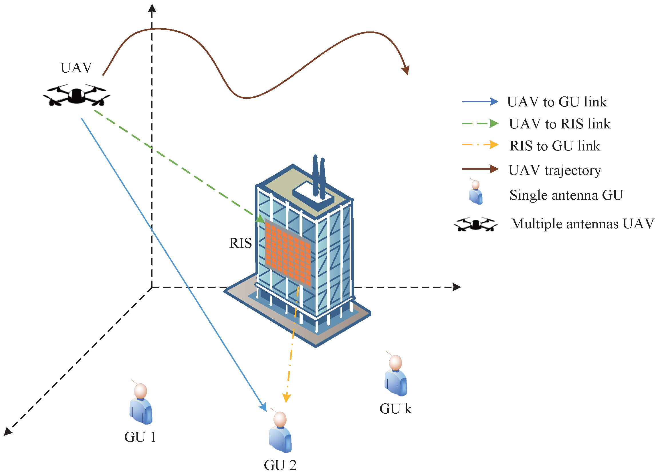
Consider a communication system featuring a UAV equipped with multiple antennas, K ground users (GUs) with single antennas, and a RIS, as depicted in Figure 1. The MISO UAV communication system refers to a configuration where the UAV is equipped with multiple antennas for transmitting signals, while the ground user receives these signals through a single antenna. In order to maintain the RIS in the line of sight between the UAV and the ground users, we strategically locate the RIS at the perimeter of the service area, directly facing all the ground users. In such cases, UAVs and RISs are deployed to offload traffic, thereby improving the communication quality for ground users. The UAV is equipped with L antennas, which facilitate downlink transmission services to the ground users. During a single time slot, we presume that only one ground user is capable of receiving both the UAV’s direct signal and the RIS-assisted signal simultaneously. The UAV and RIS provide services to the GUs within a fixed time T. The entire service duration is segmented into N equal time slots, with each time slot designated as . The RIS, the kth GU, and the UAV have their respective coordinates represented as follows: the RIS at , the kth GU at , and the UAV at time slot n at . In this context, the index of the ground user is denoted by k, where k belongs to the set defined as . Additionally, the variable n signifies the time slot, and it is taken from the set defined as . For computational simplicity, we assume the channel state remains constant throughout a time slot. During the nth time slot, the UAV’s position must conform to certain constraints
where is UAV’s starting position and represents the ending position. The UAV’s maximum velocity is designated as and the maximum distance it can fly within a time slot is represented by .

Figure 1.
RIS-assisted MISO UAV communication system.
Let represent a binary scheduling variable for users, where a value of means UAV provides communication service to the kth GU during the nth time slot. Conversely, if , it signifies that no such service is being provided during that particular time slot [22]. These definitions lead to the following constraints
The RIS features a three-layer design with a controller for exact reflection manipulation. Its inner layer dynamically tunes reflection coefficients for various communication demands. A copper backplane in the middle prevents signal leakage. The outer layer hosts numerous reflecting elements on a dielectric substrate, each adjustable in amplitude and phase via the controller, to direct signals to a specific receiver. RIS is extensively used to establish an auxiliary link that significantly boosts communication system performance. By enabling signals to resist interference more effectively during transmission, this technology enhances signal stability and reliability, leading to a smoother and more efficient communication experience for users. The RIS is constructed by M reflecting elements which form a uniform planar array (UPA) with and antennas in the horizontal and vertical directions, respectively. The RIS controller can intelligently adjust each element’s phase shift to improve communication quality. Let denote the matrix of phase shift, where is the mth reflecting element’s phase shift [26]. Through this diagonal matrix, the linear relationship between the incident signal and the reflected signal becomes evident, laying the mathematical foundation for the RIS to attain accurate signal reflection.
The UAV operates at a sufficient altitude, allowing a link between UAV to GUs (U2G link) as a LoS channel. However, in the real world, particularly in an urban environment, numerous obstacles potentially block the LoS path between the UAV and the GUs. The U2G link channel for the kth ground user during the nth time slot is modeled by a Rayleigh fading channel, denoted by [24]
where represents the path loss at a reference distance of m and denotes the corresponding path loss exponent for the U2G link. The distance between the UAV and the kth ground user during the nth time slot is given by . Furthermore, represents the random scattering component, modeled as a circularly symmetric complex Gaussian (CSCG) random variable with zero mean and unit variance [26].
Since the RIS has been mounted on the building’s facade, we can presume a direct LoS connection link between the RIS and UAV (U2R link) [24]. The U2R link channel is
where and where and are expressed as and . and [17].
In accordance with the assumption of the channel model in [25], the connection between the RIS and ground user k (R2G link) can be modeled as a Rician fading channel. This channel, denoted as , is defined as
where , the deterministic LoS component can be expressed as and the non-line-of-sight (NLoS) component is regarded as a distribution with unit variance and zero mean. The distance between each antenna is denoted as d, while the carrier wavelength is represented by . denotes the cosine of the angle of arrival for the signal transmitted from the RIS to the k-th ground user. Similarly, signifies the sine of this angle of arrival. The computation of these angles is based on the geometric relationships and signal propagation characteristics within the system. is the R2G link’s path loss and the Rician factor is . It is assumed that the channel state information (CSI) is acquired through established channel estimation methods, similar to those described in [28].
Let the transmit information from the UAV be beamformed by . The transmit beamforming has the power constraint which is defined as
where P represents the allocated power budget. The signal-to-noise ratio (SNR) for ground user k during nth time slot is defined as follows
where denotes the power of noise, and . The data transmission rate for the kth ground user during the nth time slot is given by
Hence the achievable rate during the total flight duraiton for the kth GU is given by
2.2. Problem Formulation
In this letter, our objective is to increase the minimum achievable user rate via optimizing the user scheduling , UAV’s transmit beamforming , the RIS’s phase shift and UAV’s trajectory during all communication time slots. Thus, the problem is expressed in terms of
In problem (13), Constraint (1), (2) and (3) define the starting and ending locations of the UAV, along with the highest velocity it is capable of reaching. Constraint (4) and (5) guarantee that, within a given time slot, the UAV is limited to servicing a single user, while constraint (9) limits the UAV’s transmission power. Constraint (13c) applies restrictions on the phase adjustments of the RIS. The user scheduling consists of binary variables, while the constraint imposed by the UAV’s trajectory renders the optimization problem non-convex. Consequently, problem (13) is classified as a non-convex optimization problem that involves a mix of integer variables.
3. The Proposed Algorithm
In this section, we segment problem (13) into four separate subproblems for individual consideration. UAV’s transmit beamforming can be solved as a closed-form expression. To maximize the minimum achievable user rate, we align the phases of the signals received from both the U2G and R2G links at the user’s end. Additionally, we employ the successive convex approximation method to determine the optimal trajectory for the UAV.
3.1. User Scheduling Optimization
We define the minimum value of achievable user rate among all GUs as . Then we relax into a continuous variable. Problem (13) can be reformulated with fixed transmit beamforming , UAV’s trajectory and RIS’s phase shift
It should be emphasized that all constraints presented in (14) are convex, making (14) a linear optimization problem. Therefore, we can employ the CVX toolbox to solve this problem directly.
3.2. Transmit Beamforming Optimization
In this subsection, we provide the optimization of transmit beamforming for the given user scheduling , UAV’s trajectory and RIS’s phase shift . Since the user scheduling is fixed, and each GU’s rate in every time slot is independent, the problem can be reframed as optimizing the data rate for the kth ground user during time slot n to achieve maximum performance. Denote . Hence, the transmit beamforming optimization problem can be alternatively formulated as follows
Let be a feasible solution for (15) that can be derived from the th round. Io order to generate , which ensure
then use the following inequality [18]
for , and , , yields
with , , and .
The function is concave and we can use Lagrangian method to find at the th iterationin terms of the following closed-form expression:
where and is chosen by bisection such that .
3.3. Phase Shift Optimization
We use the given and to optimize the phase shift . The achievable rate can be maximized for kth GU at time slot n if the received signals from direct path and reflected path are combined coherently.
For the fixed transmit beamforming and channel gains , and , the problem of phase optimization is given by
By exploiting the structure of the objective function, we can obtain the solution to the aforementioned non-convex problem. The inequality is expressed as follows
the equality holds only when . The solution that satisfies both this equality and the constraints of phase shift in (20b) can be obtained. Let where and with (21), problem (20) is equivalent to
The problem’s optimal solution is represented by the formula . Consequently, the phase shift for the mth element in the nth time slot at the RIS is determined as follows
where is the mth element of , and represents the mth row vector of the matrix . By referring to (23), we are able to calculate the phase shift for the given channel gain and UAV position.
3.4. Trajectory Optimization
Leveraging the specified user scheduling , transmit beamforming , and phase shift , the data rate achieved by the kth GU during the nth time slot can be calculated as
where , , and . We maintain as a fixed value at each moment and simulate the randomness by conducting multiple repeated experiments. The optimization of the trajectory can be formulated as
Problem (25) remains non-convex concerning the UAV trajectory variable . To address this, we introduce slack variables, specifically, , . The reformulated problem is as follows
The expansions of first-order Taylor , at the given points , can express the lower bound of [24]
where
So the problem (26) can be reformulated as
By converting problem (31) into a convex optimization problem, we can efficiently solve it using the CVX tool.
3.5. Overall Algorithm
In this part, the overall algorithm for problem (13) is shown in Algorithm 1. Each point in the approximation problem provides a feasible solution for the original problem. This approach ensures that the proposed solution is relatively close to the actual optimal solution. To manage complexity, we exclude the optimization of UAV altitude. The computational complexity of the proposed algorithm is , where indicates the number of iterations.
Throughout the process of optimizing the UAV’s trajectory, we employ the successive convex approximation technique to refine the lower bound iteratively, ensuring convergence towards a stationary point. User scheduling involves linear optimization. The optimization for transmit beamforming and phase shift can be explicitly represented in a closed-form expression. The output of each iteration in the proposed algorithm forms a non-decreasing sequence converging to a stationary value. The algorithmic convergence is guaranteed as
| Algorithm 1 Proposed Algorithm for Solving (13) | |
| 1: | Initialization: Set iteration number and tolerance error . Initialize and with the given |
| 2: | repeat |
| 3: | Solve problem (14) to find with given , and ; |
| 4: | Solve problem (19) to find with given , and ; |
| 5: | Solve problem (23) to find with given , and ; |
| 6: | Solve problem (31) to find with given , and ; |
| 7: | Set ; |
| 8: | Until:. |
4. Numerical Results
In our simulation results, “W/o traj” refers to the proposed scheme without UAV trajectory optimization, “W/r beam” indicates the proposed scheme with random beamforming, and “A/u sche” signifies the average distribution of user scheduling time. The RIS’s coordinate is . There are five GUs whose coordinates are , , , , . The UAV starts at position and ends at position . Other parameters include , s, dBm, , , , , , dB, dB and [24]. The remaining simulation parameters are detailed in Table 1.

Table 1.
Simulation parameter settings.
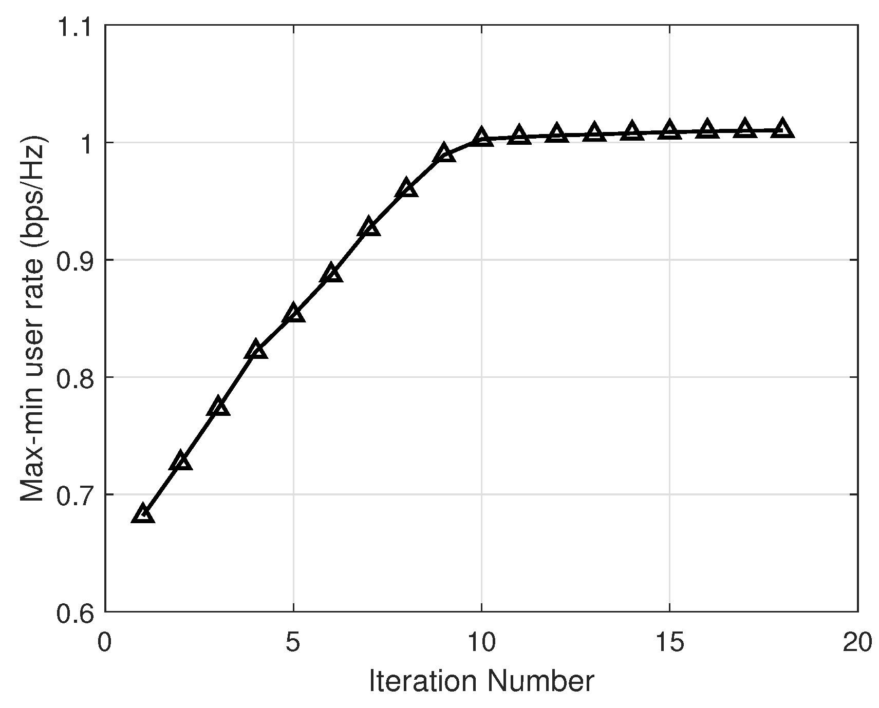
Figure 2 depicts the convergence trend of the algorithm we proposed, which achieves convergence within 20 iterations. The proposed algorithm shows substantial performance enhancement, achieving a 40% boost in the max-min user rate from the starting iteration until convergence. Moreover, after the first 9 iterations, during which the objective value experiences rapid growth, the subsequent iterations indicate a trend towards stability. Overall, the algorithm exhibits a monotonically non-decreasing behavior.
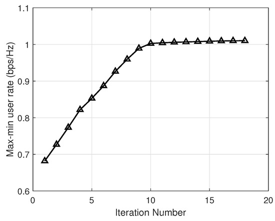
Figure 2.
Max-min user rate versus the iteration number.
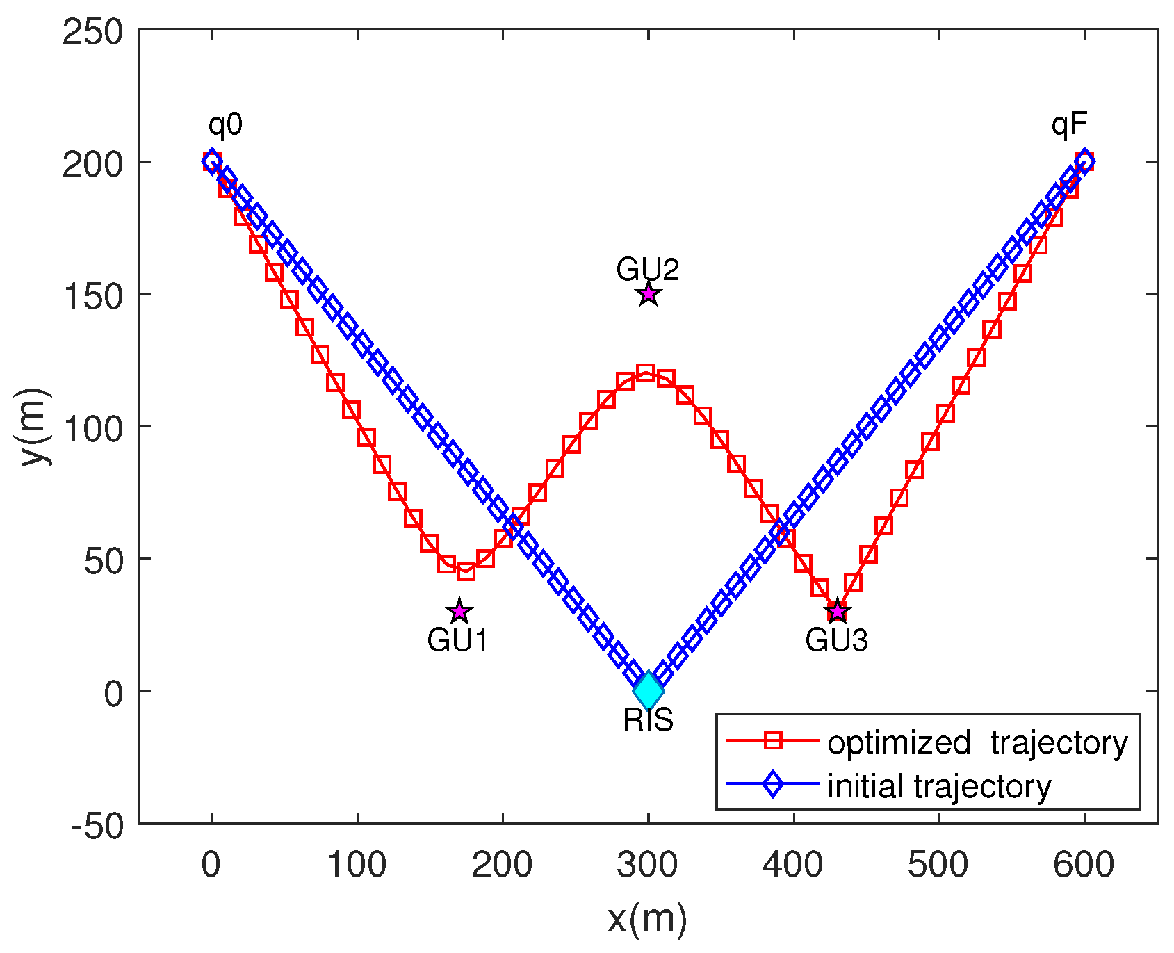
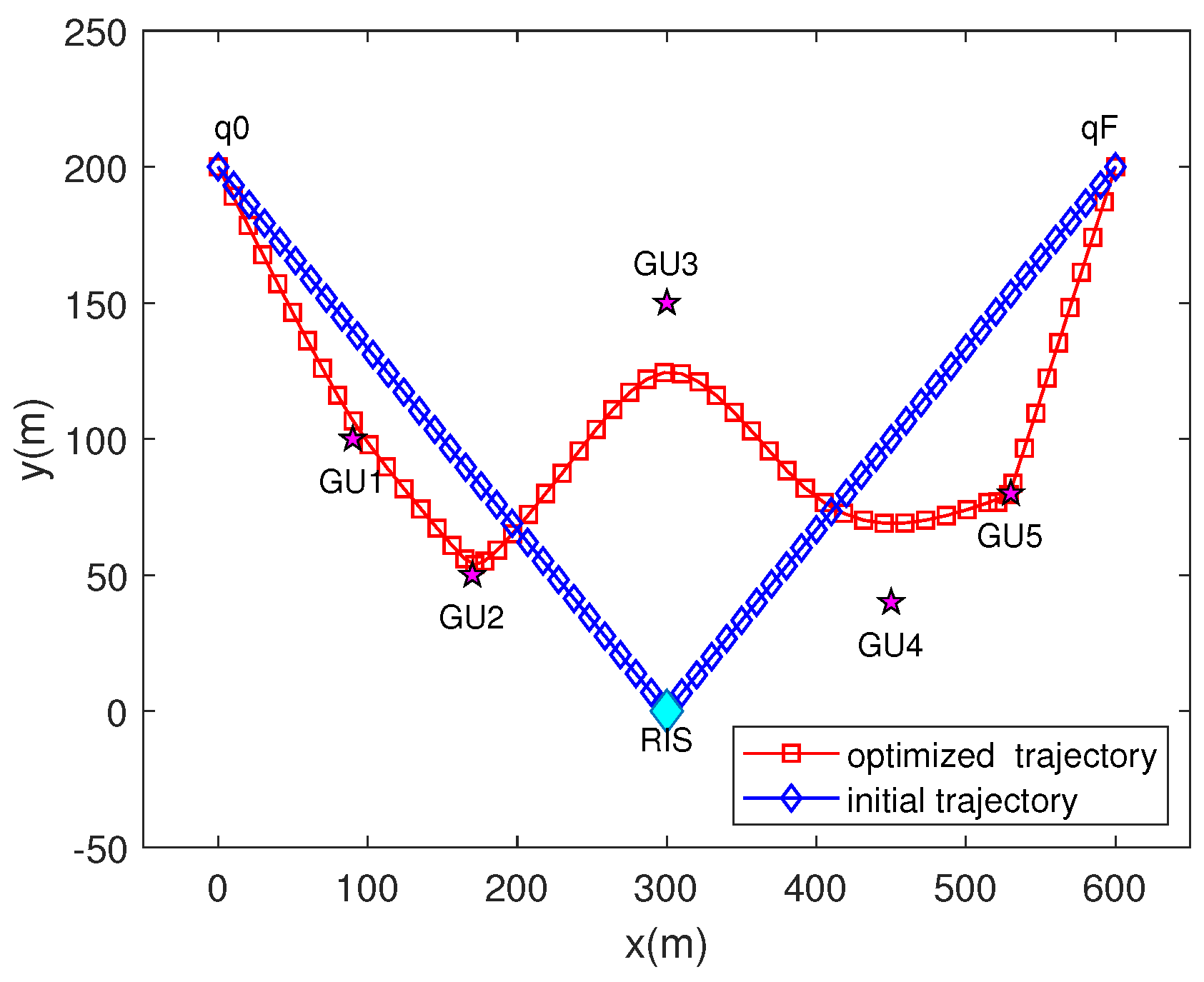
Figure 3 and Figure 4 present the initial and optimized trajectories of the UAV in scenarios with 3 and 5 ground users, respectively. Through trajectory optimization, the channel gains of both links for the kth GU in each time slot are balanced. When a GU is selected, the UAV adjusts its position to minimize the communication distance, thereby enhancing service quality. The objective of maximizing the minimum user rate (i.e., max-min user rate) drives the UAV to serve each GU as equitably as possible. Subsequent experimental data focuses on scenarios with 5 ground users as the primary target.

Figure 3.
UAV trajectory with three ground users.
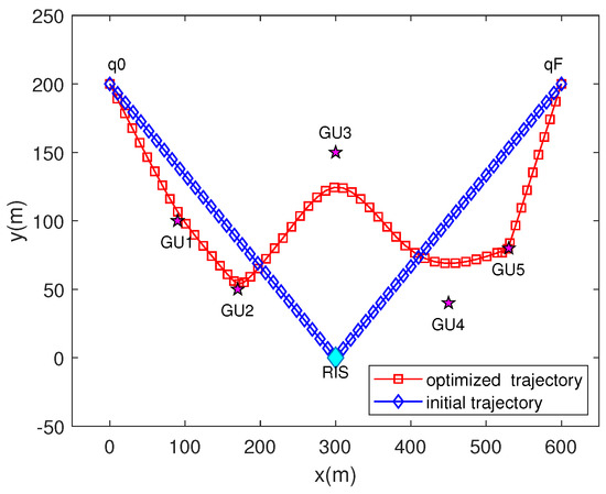
Figure 4.
UAV trajectory with five ground users.
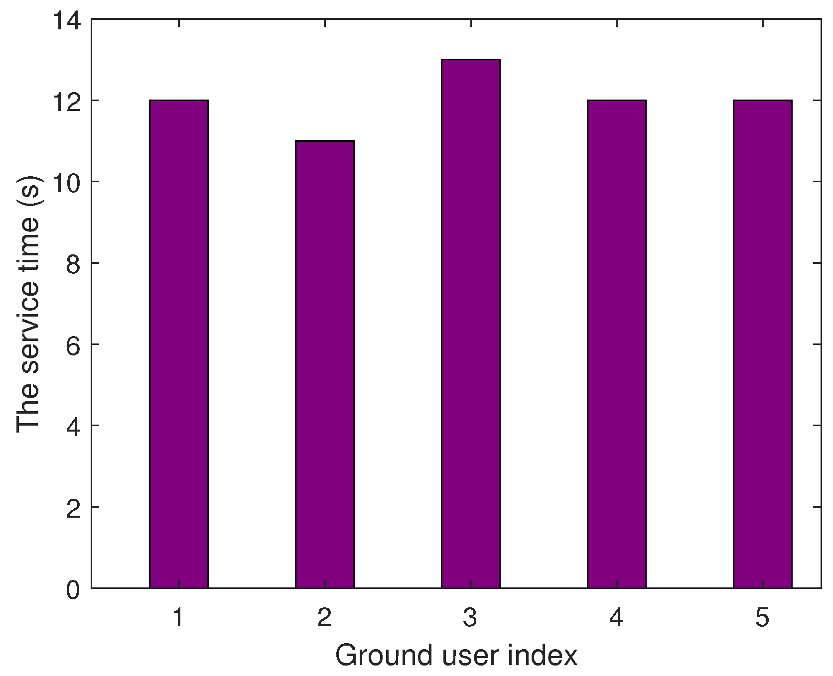
Figure 5 illustrates the varying service times provided by the UAV to each ground user. GU2 enjoys a shorter service time due to its proximity to the RIS and the UAV’s trajectory directly passing over GU2. Conversely, GU3 experiences a longer service time as it is farther from the RIS and not directly beneath the UAV’s trajectory. These adjustments aim to ensure a fairer distribution of service among all users.
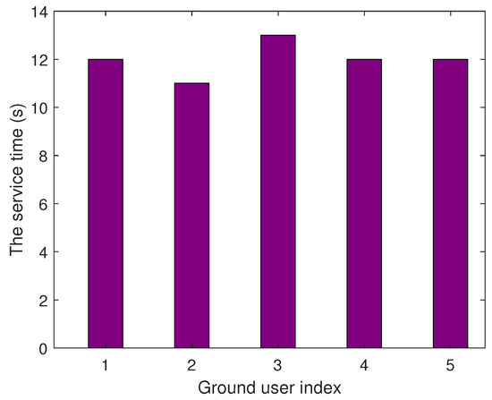
Figure 5.
The service time provided for each user.
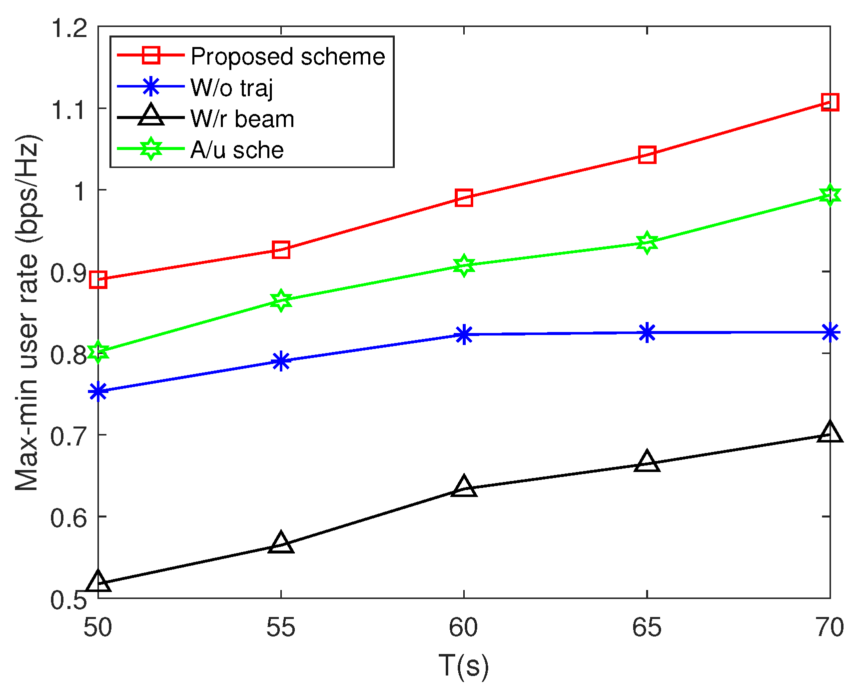
Figure 6 illustrates the max-min user rate versus service time T of different schemes. Increasing the service time leads to a higher max-min user rate. This improvement arises from the UAV’s ability to remain in an optimal position for longer durations, enhancing its ability to serve users effectively. By adjusting its trajectory according to the positions of the RIS and users, the UAV can achieve better positioning, thereby boosting the average transmission rate. On the contrary, reducing the service duration could restrict the UAV’s capacity to arrive at an ideal location during the allocated time, thus affecting its overall performance. Simulation results demonstrate that the proposed scheme can achieve a higher max-min user rate than the “W/o traj”, “A/u sche” and “W/r beam” schemes. Furthermore, optimizing the UAV’s transmit beamforming yields the greatest improvement in the max-min user rate.

Figure 6.
Max-min user rate versus time.
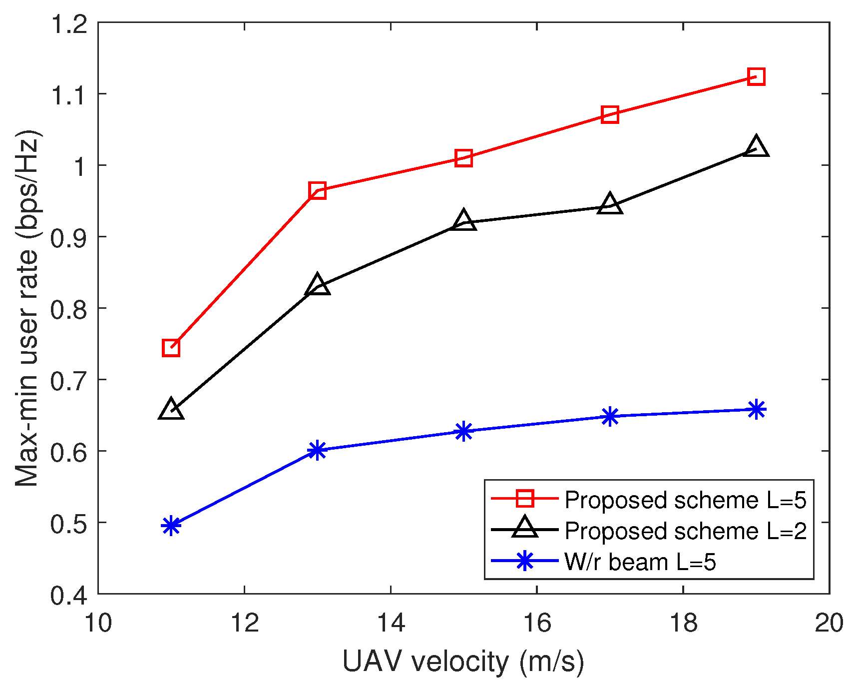
Figure 7 illustrates the max-min user rate for different schemes versus UAV velocity under conditions of and W. The proposed approach demonstrates improved performance as UAV velocity increases. When the UAV’s velocity is capped at 11 m/s, there is a sharp decline in the max-min user rate. This decline is attributed to the UAV’s trajectory being unable to directly cover the users and the limited time available for hovering. Conversely, once the UAV’s velocity surpasses 13 m/s, its trajectory stabilizes. Nonetheless, an increase in UAV velocity leads to extended hover times above the users, resulting in a more consistent growth in the max-min user rate. Furthermore, we compared scenarios where the UAV was equipped with 2 and 5 transmitting antennas. The findings revealed that augmenting the antenna count significantly boosts data transmission rates. This enhancement is due to the increased precision in beamforming and higher signal gain achieved by the additional antenna elements, ultimately elevating signal strength and transmission rate. Additionally, the multi-antenna setup provides superior interference resistance, guaranteeing data transmission.
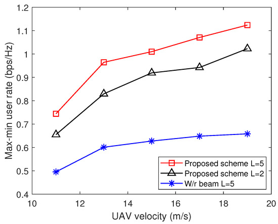
Figure 7.
Max-min user rate versus UAV velocity.
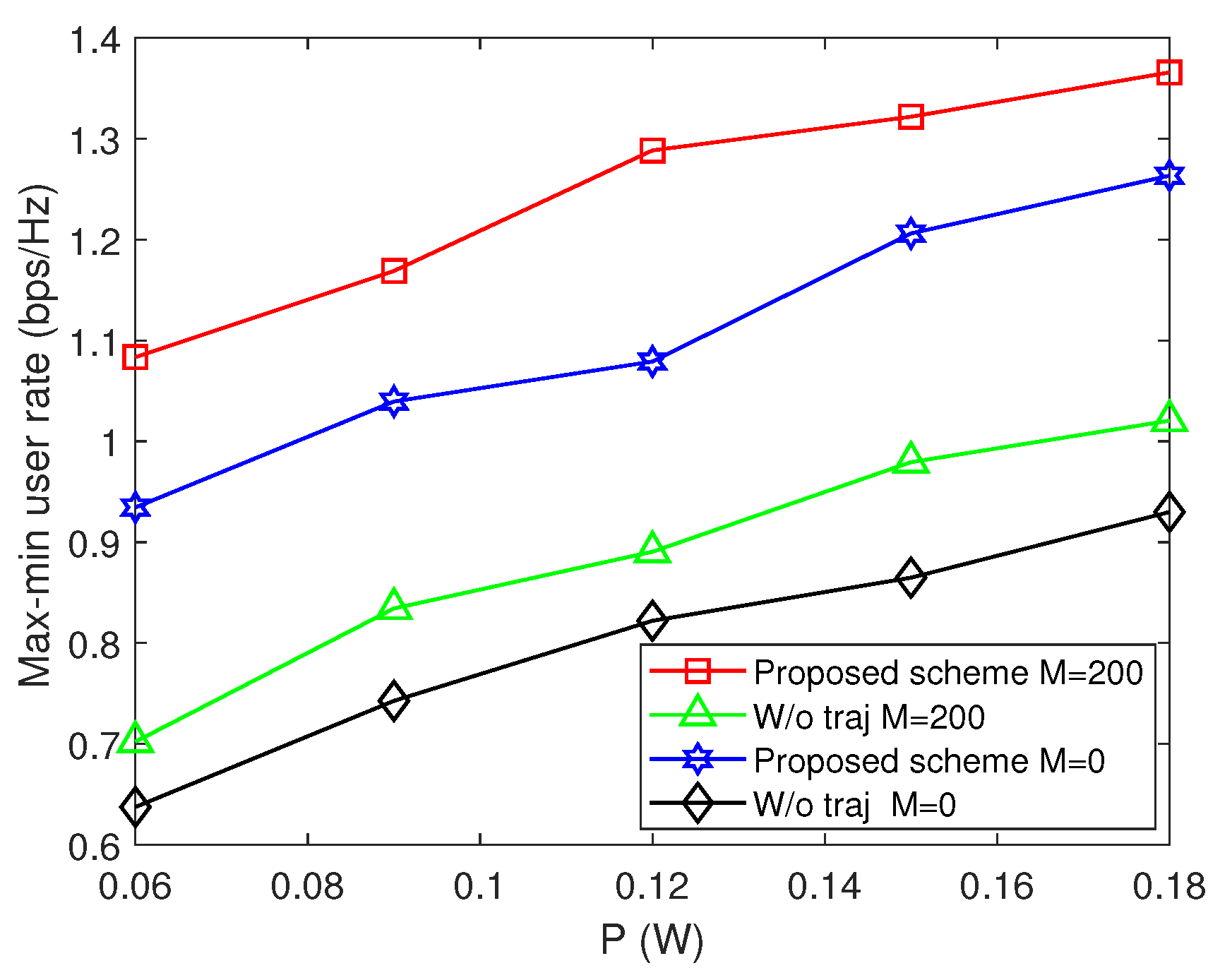
In Figure 8, we present the max-min user rate for various schemes as a function of power. The simulation results indicate that our proposed optimization method, which includes UAV trajectory optimization, outperforms the baseline scheme without such optimization. This highlights the crucial role of UAV trajectory optimization in enhancing the max-min user rate. Additionally, as the UAV’s transmission power increases, the max-min user rate exhibits a steady growth trend. We also compare the performance of utilizing 200 reflecting elements with that of not using RIS. The results demonstrate that utilizing RIS can enhance the max-min user rate by approximately 15%. Consequently, equipping additional RIS reflecting elements enables achieving the same rate with reduced transmission power, leading to significant energy savings.
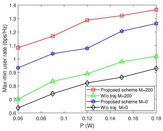
Figure 8.
Max-min user rate versus power.
5. Conclusions
In this article, the RIS-assisted MISO UAV communication system was investigated, where the RIS is employed to create an auxiliary link to enhance communication performance. The use of multi-antenna UAV for data transmission aims to mitigate interference and enhance system energy and spectral efficiency. To ensure fair transmission services for ground users, our approach jointly optimizes user scheduling, UAV’s transmit beamforming, RIS phase shift, and UAV’s trajectory. We employed the SCA method to optimize the lower bound in each iteration, ensuring convergence towards a stationary point. Additionally, we proposed an alternating iterative optimization algorithm to maximize the minimum transmission rate among users. Simulation results indicate the excellence of our proposed algorithm compared to other benchmark methods. Moreover, we observed that optimizing the phase shift of the RIS can significantly enhance the transmission rate. The UAV considers the positions of the RIS and users to determine its final trajectory. Increasing the UAV’s transmission energy consumption and speed can boost the average transmission rate. Similarly, extending the service time increases the average transmission rate as the UAV spends more time hovering. Although adding reflecting elements complicates phase adjustment, it effectively enhances the system’s transmission rate without increasing energy consumption.
Author Contributions
Conceptualization, Y.G. (Yang Gu); methodology, Y.G. (Yang Gu); software, Y.G. (Yang Gu); validation, Y.G. (Yuan Gao), Y.F. and Z.H.; formal analysis, Y.G. (Yang Gu); investigation, Y.G. (Yang Gu); writing—original draft preparation, Y.G. (Yang Gu); writing—review and editing, Y.G. (Yuan Gao); supervision, Y.F., Z.H. and Y.G. (Yuan Gao); project administration, Y.F. and Y.G. (Yuan Gao). All authors have read and agreed to the published version of the manuscript.
Funding
This work was supported in part by the National Natural Science Foundation of China (NSFC) under Grant 61901254, in part by the Aeronautical Science Foundation of China under Grant 2020Z0660S6001 and in part by the Innovation Program of Shanghai Municipal Science and Technology Commission under Grant 22511103202.
Data Availability Statement
Data are contained within the article.
Conflicts of Interest
The authors declare no conflicts of interest.
Abbreviations
The following abbreviations are used in this manuscript:
| CSI | channel state information |
| CSCG | circularly symmetric complex gaussian |
| R2G link | link between the RIS and ground user |
| U2R link | link between the RIS and UAV |
| U2G link | link between UAV to ground user |
| MISO | multiple-input single-output |
| NLoS | non-line-of-sight |
| RIS | reconfigurable intelligent surface |
| SNR | signal-to-noise ratio |
| UPA | uniform planar array |
| UAV | unmanned aerial vehicle |
| LoS | line-of-sight |
References
- Liu, Y.; Xie, S.; Zhang, Y. Cooperative Offloading and Resource Management for UAV-Enabled Mobile Edge Computing in Power IoT System. IEEE Trans. Veh. Technol. 2020, 69, 12229–12239. [Google Scholar] [CrossRef]
- Tyrovolas, D.; Mekikis, P.-V.; Tegos, S.A.; Diamantoulakis, P.D.; Liaskos, C.K.; Karagiannidis, G.K. Energy-Aware Design of UAV-Mounted RIS Networks for IoT Data Collection. IEEE Trans. Commun. 2023, 71, 1168–1178. [Google Scholar] [CrossRef]
- Zhang, H.; Huang, M.; Zhou, H.; Wang, X.; Wang, N.; Long, K. Capacity Maximization in RIS-UAV Networks: A DDQN-Based Trajectory and Phase Shift Optimization Approach. IEEE Trans. Wirel. Commun. 2023, 22, 2583–2591. [Google Scholar] [CrossRef]
- Qian, Y.; Wang, F.; Li, J.; Shi, L.; Cai, K.; Shu, F. User Association and Path Planning for UAV-Aided Mobile Edge Computing with Energy Restriction. IEEE Wirel. Commun. Lett. 2019, 8, 1312–1315. [Google Scholar] [CrossRef]
- Li, Y.; Aghvami, A.H.; Dong, D. Path Planning for Cellular-Connected UAV: A DRL Solution with Quantum-Inspired Experience Replay. IEEE Trans. Wirel. Commun. 2022, 21, 7897–7912. [Google Scholar] [CrossRef]
- Li, Y.; Aghvami, A.H. Radio Resource Management for Cellular-Connected UAV: A Learning Approach. IEEE Trans. Commun. 2023, 71, 2784–2800. [Google Scholar] [CrossRef]
- Hou, X.; Wang, J.; Jiang, C.; Zhang, X.; Ren, Y.; Debbah, M. UAV-Enabled Covert Federated Learning. IEEE Trans. Wirel. Commun. 2023, 22, 6793–6809. [Google Scholar] [CrossRef]
- Feng, W.; Wang, J.; Chen, Y.; Wang, X.; Ge, N.; Lu, J. UAV-Aided MIMO Communications for 5G Internet of Things. IEEE Internet Things J. 2019, 62, 1731–1740. [Google Scholar] [CrossRef]
- Lyu, L.; Zeng, F.; Xiao, Z.; Zhang, C.; Jiang, H.; Havyarimana, V. Computation Bits Maximization in UAV-Enabled Mobile-Edge Computing System. IEEE Internet Things J. 2022, 9, 10640–10651. [Google Scholar] [CrossRef]
- Yu, Z.; Gong, Y.; Gong, S.; Guo, Y. Joint Task Offloading and Resource Allocation in UAV-Enabled Mobile Edge Computing. IEEE Internet Things J. 2020, 7, 3147–3159. [Google Scholar] [CrossRef]
- Liu, B.; Wan, Y.; Zhou, F.; Wu, Q.; Hu, R.Q. Robust Trajectory and Beamforming Design for Cognitive MISO UAV Networks. IEEE Wirel. Commun. Lett. 2021, 10, 396–400. [Google Scholar]
- Khalili, A.; Monfared, E.M.; Zargari, S.; Javan, M.R.; Yamchi, N.M.; Jorswieck, E.A. Resource Management for Transmit Power Minimization in UAV-Assisted RIS HetNets Supported by Dual Connectivity. IEEE Trans. Wirel. Commun. 2022, 21, 1806–1822. [Google Scholar] [CrossRef]
- Zeng, S.; Zhang, H.; Di, B.; Han, Z.; Song, L. Reconfigurable Intelligent Surface (RIS) Assisted Wireless Coverage Extension: RIS Orientation and Location Optimization. IEEE Commun. Lett. 2021, 25, 269–273. [Google Scholar] [CrossRef]
- ElMossallamy, M.A.; Zhang, H.; Song, L.; Seddik, K.G.; Han, Z.; Li, G.Y. Reconfigurable Intelligent Surfaces for Wireless Communications: Principles, Challenges, and Opportunities. IEEE Trans. Cogn. Commun. Netw. 2020, 6, 990–1002. [Google Scholar] [CrossRef]
- Yan, W.; Yuan, X.; He, Z.-Q.; Kuai, X. Passive Beamforming and Information Transfer Design for Reconfigurable Intelligent Surfaces Aided Multiuser MIMO Systems. IEEE J. Sel. Areas Commun. 2020, 38, 1793–1808. [Google Scholar] [CrossRef]
- He, Z.; Shen, H.; Xu, W.; Zhao, C. Low-Cost Passive Beamforming for RIS-Aided Wideband OFDM Systems. IEEE Wirel. Commun. Lett. 2022, 11, 318–322. [Google Scholar] [CrossRef]
- Yu, H.; Tuan, H.D.; Nasir, A.A.; Duong, T.Q.; Poor, H.V. Joint Design of Reconfigurable Intelligent Surfaces and Transmit Beamforming Under Proper and Improper Gaussian Signaling. IEEE J. Sel. Areas Commun. 2020, 38, 2589–2603. [Google Scholar] [CrossRef]
- Yu, H.; Tuan, H.D.; Dutkiewicz, E.; Poor, H.V.; Hanzo, L. Maximizing the Geometric Mean of User-Rates to Improve Rate-Fairness: Proper vs. Improper Gaussian Signaling. IEEE Trans. Wirel. Commun. 2022, 21, 295–309. [Google Scholar] [CrossRef]
- Liu, X.; Yu, Y.; Li, F.; Durrani, T.S. Throughput Maximization for RIS-UAV Relaying Communications. IEEE Trans. Intell. Transp. Syst. 2022, 23, 19569–19574. [Google Scholar] [CrossRef]
- Byun, Y.; Kim, H.; Kim, S.; Shim, B. Channel Estimation and Phase Shift Control for UAV-Carried RIS Communication Systems. IEEE Trans. Veh. Technol. 2023, 72, 13695–13700. [Google Scholar] [CrossRef]
- Liu, X.; Liu, Y.; Chen, Y.; Poor, H.V. RIS Enhanced Massive Non-Orthogonal Multiple Access Networks: Deployment and Passive Beamforming Design. IEEE J. Sel. Areas Commun. 2021, 39, 1057–1071. [Google Scholar] [CrossRef]
- Yu, Y.; Liu, X.; Leung, V.C.M. Fair Downlink Communications for RIS-UAV Enabled Mobile Vehicles. IEEE Wirel. Commun. Lett. 2022, 11, 1042–1046. [Google Scholar] [CrossRef]
- Singh, S.K.; Agrawal, K.; Singh, K.; Li, C.-P.; Ding, Z. NOMA Enhanced Hybrid RIS-UAV-Assisted Full-Duplex Communication System with Imperfect SIC and CSI. IEEE Trans. Commun. 2022, 70, 7609–7627. [Google Scholar] [CrossRef]
- Li, S.; Duo, B.; Yuan, X.; Liang, Y.-C.; Renzo, M.D. Reconfigurable Intelligent Surface Assisted UAV Communication: Joint Trajectory Design and Passive Beamforming. IEEE Wirel. Commun. Lett. 2020, 9, 716–720. [Google Scholar] [CrossRef]
- Pan, Y.; Wang, K.; Pan, C.; Zhu, H.; Wang, J. UAV-Assisted and Intelligent Reflecting Surfaces-Supported Terahertz Communications. IEEE Wirel. Commun. Lett. 2021, 10, 1256–1260. [Google Scholar]
- Tian, K.; Duo, B.; Li, S.; Zuo, Y.; Yuan, X. Hybrid Uplink and Downlink Transmissions for Full-Duplex UAV Communication with RIS. IEEE Wirel. Commun. Lett. 2022, 11, 866–870. [Google Scholar] [CrossRef]
- Liu, B.; Wan, Y.; Zhou, F.; Wu, Q.; Hu, R.Q. Resource Allocation and Trajectory Design for MISO UAV-Assisted MEC Networks. IEEE Trans. Veh. Technol. 2022, 71, 4933–4948. [Google Scholar] [CrossRef]
- He, Z.-Q.; Yuan, X. Cascaded channel estimation for large intelligent metasurface assisted massive MIMO. IEEE Wirel. Commun. 2020, 9, 210–214. [Google Scholar] [CrossRef]
Disclaimer/Publisher’s Note: The statements, opinions and data contained in all publications are solely those of the individual author(s) and contributor(s) and not of MDPI and/or the editor(s). MDPI and/or the editor(s) disclaim responsibility for any injury to people or property resulting from any ideas, methods, instructions or products referred to in the content. |
© 2024 by the authors. Licensee MDPI, Basel, Switzerland. This article is an open access article distributed under the terms and conditions of the Creative Commons Attribution (CC BY) license (https://creativecommons.org/licenses/by/4.0/).